EP0112398B1 - Dosiereinrichtung - Google Patents
Dosiereinrichtung Download PDFInfo
- Publication number
- EP0112398B1 EP0112398B1 EP82111794A EP82111794A EP0112398B1 EP 0112398 B1 EP0112398 B1 EP 0112398B1 EP 82111794 A EP82111794 A EP 82111794A EP 82111794 A EP82111794 A EP 82111794A EP 0112398 B1 EP0112398 B1 EP 0112398B1
- Authority
- EP
- European Patent Office
- Prior art keywords
- groove
- metering
- housing
- rotor
- metering apparatus
- Prior art date
- Legal status (The legal status is an assumption and is not a legal conclusion. Google has not performed a legal analysis and makes no representation as to the accuracy of the status listed.)
- Expired
Links
- 239000000463 material Substances 0.000 claims abstract description 7
- 238000011144 upstream manufacturing Methods 0.000 claims 1
- 239000013590 bulk material Substances 0.000 description 15
- 238000005299 abrasion Methods 0.000 description 2
- 238000009533 lab test Methods 0.000 description 2
- 239000002245 particle Substances 0.000 description 2
- 230000001154 acute effect Effects 0.000 description 1
- 238000001311 chemical methods and process Methods 0.000 description 1
- 238000004140 cleaning Methods 0.000 description 1
- 238000005056 compaction Methods 0.000 description 1
- 238000005260 corrosion Methods 0.000 description 1
- 230000007797 corrosion Effects 0.000 description 1
- 230000001419 dependent effect Effects 0.000 description 1
- 230000005484 gravity Effects 0.000 description 1
- 238000012423 maintenance Methods 0.000 description 1
- 238000004519 manufacturing process Methods 0.000 description 1
- 239000007787 solid Substances 0.000 description 1
- 239000000126 substance Substances 0.000 description 1
Images

Classifications
-
- B—PERFORMING OPERATIONS; TRANSPORTING
- B65—CONVEYING; PACKING; STORING; HANDLING THIN OR FILAMENTARY MATERIAL
- B65G—TRANSPORT OR STORAGE DEVICES, e.g. CONVEYORS FOR LOADING OR TIPPING, SHOP CONVEYOR SYSTEMS OR PNEUMATIC TUBE CONVEYORS
- B65G65/00—Loading or unloading
- B65G65/30—Methods or devices for filling or emptying bunkers, hoppers, tanks, or like containers, of interest apart from their use in particular chemical or physical processes or their application in particular machines, e.g. not covered by a single other subclass
- B65G65/34—Emptying devices
- B65G65/40—Devices for emptying otherwise than from the top
- B65G65/48—Devices for emptying otherwise than from the top using other rotating means, e.g. rotating pressure sluices in pneumatic systems
- B65G65/4881—Devices for emptying otherwise than from the top using other rotating means, e.g. rotating pressure sluices in pneumatic systems rotating about a substantially horizontal axis
-
- B—PERFORMING OPERATIONS; TRANSPORTING
- B01—PHYSICAL OR CHEMICAL PROCESSES OR APPARATUS IN GENERAL
- B01J—CHEMICAL OR PHYSICAL PROCESSES, e.g. CATALYSIS OR COLLOID CHEMISTRY; THEIR RELEVANT APPARATUS
- B01J8/00—Chemical or physical processes in general, conducted in the presence of fluids and solid particles; Apparatus for such processes
- B01J8/0015—Feeding of the particles in the reactor; Evacuation of the particles out of the reactor
- B01J8/002—Feeding of the particles in the reactor; Evacuation of the particles out of the reactor with a moving instrument
-
- G—PHYSICS
- G01—MEASURING; TESTING
- G01F—MEASURING VOLUME, VOLUME FLOW, MASS FLOW OR LIQUID LEVEL; METERING BY VOLUME
- G01F13/00—Apparatus for measuring by volume and delivering fluids or fluent solid materials, not provided for in the preceding groups
- G01F13/001—Apparatus for measuring by volume and delivering fluids or fluent solid materials, not provided for in the preceding groups for fluent solid material
Definitions
- the invention relates to a metering device, in particular for fine metering, for embankment-forming bulk goods, consisting of a housing provided with a feed and discharge opening, in which a rotor is arranged which has a groove.
- a roller divider is known in which the material to be conveyed is drawn out of the feed hopper in grooves which are arranged parallel to the axis, in order to then freely fall out after being conveyed along the housing wall.
- the disadvantage of this device is that a continuous delivery is not possible, since the moment the groove leaves the surrounding housing, it immediately runs completely empty. An equalization of the dosage can be achieved by increasing the throughput, which is generally not suitable for laboratory tests because of the amount. Forced cleaning of the grooves is also technically difficult, so that the roller distributor can hardly be used for adhering products. Furthermore, the parallel edges of the grooves and opening create undesirable abrasion, and even a jammed product can be expected to block the metering device.
- Known is a feed device for solid particles which are fed via a funnel to a nip between two rollers running in opposite directions, in order then to be transported downwards through this or through circumferential grooves along the circumference of the rollers.
- the invention has for its object to find a product-friendly metering device that allows continuous addition of bulk goods with high metering accuracy - especially for very small quantities.
- the object was achieved in that there is a corresponding tangent on the metering path between the edge of the housing directly opposite the groove in the area of the inlet or outlet opening of the bulk material and a deepest point of the cross section of the groove with an angle to the horizontal which is smaller is the angle between the slope and the horizontal that forms there for the respective bulk material.
- the cross-sectional dimensions of which are at least a multiple of the maximum particle size a free-flowing bulk material can be continuously added in a predetermined amount, the rotating rotor ensuring that there are no blockages and thus irregularities in the feed.
- Appropriate directions of the circumferential groove to the vertical plane can also influence the promotion depending on the location of additional frictional forces.
- the device has a simple, compact structure which facilitates maintenance and a change of conveyed goods.
- the acute angle of the line which lies in the plane through the circumference of the groove base on the rotor and the inner edge of the housing opening, is smaller than the slope or flow angle of the bulk material to be metered inside the groove, this can be filled out, but it can be shot through the bulk material is no longer possible.
- the desired dosing quantity is then only dependent on the groove volume and the speed of the rotor. This makes the dosing error very low, especially when adding the smallest quantities. At the same time, the bulk material is treated carefully.
- the components which are subjected to the product have different coefficients of friction.
- the bulk material is guided to the discharge point without any significant change in the structure, which increases the metering accuracy and reduces abrasion on the housing.
- the grooved cross section has a predetermined shape.
- the volume delivered can be specified while changing the driving area.
- a triangle is e.g. for small quantities, a rectangular trough suitable for larger quantities. If the bulk material diameter is uneven, a groove with a semicircular cross section should be preferred.
- an allocation device is arranged in front of the groove.
- a metering device which can consist, for example, of a loosener (agitator) or compressor (roller wheel), it is possible to avoid bridging and to introduce the bulk material into the groove with a uniform density, so that the metering accuracy is increased even further.
- a scraper is arranged at the discharge point.
- the scraper makes it possible to completely clean the groove with each cycle, even with caked bulk material, so that a high dosing accuracy is achieved.
- Bulk material is filled into a feed hopper 2, which then - possibly with equalization of the supply by an allocation device 11 - automatically trickles through the feed opening 3 to form a constant slope along a circumferential groove of the rotor 5, the geometric dimensions being such that the discharge of the bulk material ends before the point in the groove 6, from which the bulk material would overcome the frictional forces due to the inclination due to gravity.
- the bulk material is then taken along continuously by rotating the rotor 5, a precisely metered amount being conveyed by the speed and the filling of the groove 6 until it finally falls down automatically through the discharge opening 10. Any remaining residues are then removed from the groove 6 by a scraper 9.
- the metering device is expediently constructed using materials which have the necessary hardness and corrosion resistance in relation to the bulk material to be conveyed. It can make sense to manufacture the rotor or its product-loaded parts from a different material than the housing or its product-loaded parts.
Landscapes
- Chemical & Material Sciences (AREA)
- Fluid Mechanics (AREA)
- Chemical Kinetics & Catalysis (AREA)
- Engineering & Computer Science (AREA)
- Mechanical Engineering (AREA)
- Physics & Mathematics (AREA)
- Organic Chemistry (AREA)
- General Physics & Mathematics (AREA)
- Filling Or Emptying Of Bunkers, Hoppers, And Tanks (AREA)
- Weight Measurement For Supplying Or Discharging Of Specified Amounts Of Material (AREA)
- Coating Apparatus (AREA)
- Rolls And Other Rotary Bodies (AREA)
- Measuring Pulse, Heart Rate, Blood Pressure Or Blood Flow (AREA)
- Eye Examination Apparatus (AREA)
Description
- Erfindung betrifft eine Dosiereinrichtung, insbesondere zur Feindosierung, für böschungsausbildende Schüttgüter, bestehend aus einem mit Aufgabe- und Austragsöffnung versehenem Gehäuse, in dem ein Rotor angeordnet ist, der eine Rille besitzt.
- Bei verschiedenen chemischen Prozessen sind oft rieselfähige Stoffe kontinuierlich zuzusetzen. Besondere Schwierigkeiten bereiten dabei kleinste Mengen, wie sie beispielsweise bei Laborversuchen zugeführt werden müssen.
- Bekannt ist ein Walzenzuteiler, bei dem das Fördergut in Rillen die parallel zur Achse angeordnet sind, aus dem Aufgabetrichter abgezogen wird, um dann nach Förderung entlang der Gehäusewandung unten frei herauszufallen.
- Der Nachteil dieser Vorrichtung besteht darin, daß eine kontinuierliche Abgabe nicht möglich ist, da in dem Augenblick, in dem die Rille das umgebene Gehäuse verläßt, diese sofort vollständig leer läuft. Eine Vergleichmäßigung der Dosierung ist zwar durch die Erhöhung des Durchsatzes zu erreichen, der im allgemeinen dann wegen der Menge für Laborversuche nicht weiter geeignet ist. Auch ist eine Zwangssäuberung der Rillen technisch schwierig, so daß der Walzenzuteiler fur anhaftende Produkte kaum einsetzbar ist. Weiter erzeugen die parallelen Kanten von Rillen und Öffnnung einen unerwünschten Abrieb, ja es ist sogar durch eingeklemmtes Produkt mit einer Blockierung der Dosiereinrichtung zu rechnen.
- Bekannt (GB-A-1 402 429) ist eine Zuführeinrichtung für feste Teilchen, die über einen Trichter einem Spalt zwischen zwei gegensinnig laufenden Walzen zugeführt werden, um dann durch diesen oder durch umlaufende Rillen entlang des Umfanges der Walzen nach unten abtransportiert zu werden.
- Durch die Zwangsförderung tritt eine ungewollte Verdichtung auf, die eine genaue Dosierung erschwert und zu Verklumpungen führen kann.
- Der Erfindung liegt die Aufgabe zugrunde, eine produktschonende Dosiervorrichtung zu finden, die eine kontinuierliche Zugabe von Schüttgütern bei hoher Dosiergenauigkeit - insbesondere bei Kleinstmengen - erlaubt.
- Die Aufgabe wurde erfindungsgemäß dadurch gelöst, daß auf dem Dosierweg eine korrespondierende Tangente zwischen der der Rille unmittelbar gegenüberliegenden Kante des Gehäuses im Bereich von Ein- oder Austrittsöffnung des Schüttgutes und einer tiefsten Stelle des Querschnittes der Rille mit einem Winkel zur Horizontalen vorhanden ist, der kleiner ist als der dort bei dem jeweiligen Schüttgut sich ausbildende Winkel zwischen Böschung und Horizontalen.
- Durch die erfindungsgemäße Rille, deren Querschnittsabmessungen mindestens ein Mehrfaches der maximalen Teilchenabmessung betragen, kann kontinuierlich ein rieselfähiges Schüttgut in vorgegebener Menge zugegeben werden, wobei der drehende Rotor sicherstellt, daß keine Verstopfungen und damit Unregelmäßigkeiten in der Zufuhr eintreten. Durch entsprechende Richtungsvorgaben der umlaufenden Rille zur lotrechten Ebene kann darüberhinaus die Förderung je nach Lage zusätzlich entsprechender Reibungskräfte beeinflußt werden. Die Vorrichtung besitzt einen einfachen, kompakten Aufbau, der die Instandhaltung und einen Fördergutwechsel erleichtert.
- Wenn der spitze Winkel der Linie, die in der Ebene durch Umfang des Rillenfußes am Rotor und innerer Kante der Gehäuseöffnung liegt, kleiner ist als der Böschungs- bzw. Fließwinkel des zu dosierenden Schüttgutes innerhalb der Rille, kann diese zwar ausgefüllt werden, aber ein Durchschießen des Schüttgutes ist nicht mehr möglich. Die gewünschte Dosiermenge ist dann nur noch von dem Rillenvolumen und der Drehzahl des Rotors abhängig. Hierdurch wird der Dosierfehler, insbesondere bei Zugabe von kleinsten Mengen, sehr gering. Gleichzeitig wird das Schüttgut schonend behandelt.
- In einer besonderen Ausführungsform weisen die produktbeaufschlagten Bauteile unterschiedliche Reibungskoeffizienten auf.
- Durch beispielsweise rauhe Mitnahmeflächen in der Rille und glatte Gleitflächen im Gehäuse wird das Schüttgut ohne wesentliche Veränderung der Struktur zur Austragsstelle geleitet, wodurch die Dosiergenauigkeit erhöht und ein Abrieb am Gehäuse verringert wird.
- In einer weiteren Ausführungsform hat der Rillenguerschnitt eine vorgegebene Form.
- Durch die Form der Rille kann das geförderte Volumen bei gleichzeitiger Veränderung der Mitnahmefläche vorgegeben werden. Ein Dreieck ist z.B. für kleine Mengen, eine Rechteckrinne für größere Mengen geeignet. Bei ungleichmäßigem Korndurchmesser des Schüttgutes ist eine Rille mit halbkreisförmigem Querschnitt vorzuziehen.
- In einer anderen Ausführungsform ist vor der Rille eine Zuteilvorrichtung angeordnet.
- Mit einer Zuteilvorrichtung, die beispielsweise aus einem Auflockerer (Rührwerk) oder Verdichter (Walzenrad) bestehen kann, ist es möglich, eine Brückenbildung zu vermeiden und das Schüttgut mit einer gleichmäßigen Dichte in die Rille einzubringen, so daß die Dosiergenauigkeit noch weiter erhöht wird.
- In einer Ausführungsform ist an der Austragsstelle ein Abstreifer angeordnet.
- Durch den Abstreifer ist es möglich, auch bei anbackendem Schüttgut die Rille bei jedem Umlauf restlos zu säubern, so daß eine hohe Dosiergenauigkeit erreicht wird.
- Ein Beispiel der Erfindung ist in den Zeichnungen dargestellt und wird im folgenden beschrieben. Es zeigen:
- Fig. 1 Querschnitt durch Walze,
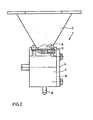
- Fig. 2 Längsschnitt durch Walze.
- In Fig. 1 und 2 ist eine Dosiervorrichtung 1 dargestellt, bei der ein Aufgabetrichter 2 mit Aufgabeöffnung 3 über einem um die Achse 4 drehende Rotor 5 mit Rille 6 in einem Gehäuse 7 angeordnet ist. Weiter ist im Schnitt teilweise ein Deckel 8 und ein Abstreiter 9 in Austragsöffnung 10 gezeigt. Außerdem ist im Trichter 2 ein Rührer als Zuteilvorrichtung 11 und ein Schott 12 gezeigt. Der Rotor 5 und die Zuteilvorrichtung 11 werden durch nicht dargestellte Motore angetrieben.
- In einen Aufgabetrichter 2 wird Schüttgut gefüllt, welches dann - evtl. unter Vergleichmäßigung der Zufuhr durch eine Zuteileinrichtung 11 - selbsttätig durch die Aufgabeöffnung 3 unter Ausbildung einer gleichbleibenden Böschung entlang einer umlaufenden Rille des Rotors 5 rieselt, wobei die geometrischen Abmessungen so ausgebildet sind, daß der Auslauf des Schüttgutes vor der Stelle in der Rille 6 endet, ab der das Schüttgut wegen zurückstehender Neigung infolge der Schwerkraft die Reibungskräfte überwinden würde. Beim weiteren Transport wird das Schüttgut dann kontinuierlich durch Drehen des Rotors 5 mitgenommen, wobei durch die Drehzahl und die Füllung der Rille 6 eine genau dosierte Menge gefördert wird, bis diese schließlich selbsttätig durch die Austragsöffnung 10 nach unten wegfällt. Durch einen Abstreifer 9 werden dann noch evtl. verbleibende Reste aus der Rille 6 entfernt.
- Die Konstruktion der Dosiervorrichtung erfolgt zweckmäßigerweise mit solchen Materialien, die gegenüber dem zu fördernden Schüttgut die notwendige Härte und Korrosionsfestigkeit besitzen. Dabei kann es sinnvoll sein, den Rotor, bzw. dessen produktbeaufschlagte Teile aus einem anderen Material als das Gehäuse, bzw. dessen produktbeaufschlagte Teile, zu fertigen.


Claims (5)
Priority Applications (5)
| Application Number | Priority Date | Filing Date | Title |
|---|---|---|---|
| AT82111794T ATE21834T1 (de) | 1982-12-20 | 1982-12-20 | Dosiereinrichtung. |
| DE8282111794T DE3273074D1 (en) | 1982-12-20 | 1982-12-20 | Measuring device |
| EP82111794A EP0112398B1 (de) | 1982-12-20 | 1982-12-20 | Dosiereinrichtung |
| JP58236518A JPS59132317A (ja) | 1982-12-20 | 1983-12-16 | 計量装置 |
| US06/833,319 US4753374A (en) | 1982-12-20 | 1986-02-24 | Metering apparatus |
Applications Claiming Priority (1)
| Application Number | Priority Date | Filing Date | Title |
|---|---|---|---|
| EP82111794A EP0112398B1 (de) | 1982-12-20 | 1982-12-20 | Dosiereinrichtung |
Publications (2)
| Publication Number | Publication Date |
|---|---|
| EP0112398A1 EP0112398A1 (de) | 1984-07-04 |
| EP0112398B1 true EP0112398B1 (de) | 1986-09-03 |
Family
ID=8189413
Family Applications (1)
| Application Number | Title | Priority Date | Filing Date |
|---|---|---|---|
| EP82111794A Expired EP0112398B1 (de) | 1982-12-20 | 1982-12-20 | Dosiereinrichtung |
Country Status (5)
| Country | Link |
|---|---|
| US (1) | US4753374A (de) |
| EP (1) | EP0112398B1 (de) |
| JP (1) | JPS59132317A (de) |
| AT (1) | ATE21834T1 (de) |
| DE (1) | DE3273074D1 (de) |
Families Citing this family (13)
| Publication number | Priority date | Publication date | Assignee | Title |
|---|---|---|---|---|
| JPS62108828U (de) * | 1985-12-26 | 1987-07-11 | ||
| DE3818338A1 (de) * | 1988-05-30 | 1989-12-07 | Schenck Ag Carl | Dosiervorrichtung fuer die feindosierung von schuettgut |
| DE4019018C2 (de) * | 1989-06-14 | 2000-08-17 | Biene Evelyn | Vorrichtung zum Dosieren von pulverförmigem Schüttgut |
| US5056715A (en) * | 1990-02-21 | 1991-10-15 | Pfizer Inc. | Apparatus for mixing and spraying a slurry |
| DE4204852A1 (de) * | 1992-02-18 | 1993-08-26 | Danag Ag | Foerdereinrichtung |
| ES2221972T3 (es) * | 1997-03-06 | 2005-01-16 | Macchine Soncini Alberto S.P.A. | Maquina para el frotamiento y salazon de carnes crudas para curado y conservacion. |
| CN108203474B (zh) * | 2016-12-19 | 2020-07-14 | 中国石油天然气股份有限公司 | 一种固体聚烯烃催化剂的旋转加料器 |
| CN108201863B (zh) * | 2016-12-19 | 2020-07-14 | 中国石油天然气股份有限公司 | 一种聚烯烃催化剂的加料系统 |
| CN108201864B (zh) * | 2016-12-19 | 2020-07-14 | 中国石油天然气股份有限公司 | 一种聚烯烃固体催化剂的旋转加料器 |
| CN108201861B (zh) * | 2016-12-19 | 2020-07-14 | 中国石油天然气股份有限公司 | 一种聚烯烃催化剂的旋转加料器 |
| CN108201858B (zh) * | 2016-12-19 | 2020-07-14 | 中国石油天然气股份有限公司 | 一种固体聚烯烃催化剂的加料系统 |
| CN108201862B (zh) * | 2016-12-19 | 2020-07-14 | 中国石油天然气股份有限公司 | 一种聚烯烃固体催化剂的加料系统 |
| US12416517B2 (en) * | 2023-12-29 | 2025-09-16 | Yuanhao ZHOU | Device for dosing particulate material |
Family Cites Families (16)
| Publication number | Priority date | Publication date | Assignee | Title |
|---|---|---|---|---|
| US25382A (en) * | 1859-09-13 | Improvement in seed-drills | ||
| US504718A (en) * | 1893-09-12 | Bkecht fkajjke | ||
| US95149A (en) * | 1869-09-21 | Improved seed-feedings device for grain-drills | ||
| DE108562C (de) * | 1900-01-01 | |||
| US2347271A (en) * | 1939-12-30 | 1944-04-25 | Standard Oil Dev Co | Feed device |
| US2440846A (en) * | 1944-03-13 | 1948-05-04 | Utah Idaho Sugar Co | Seed planter |
| GB1153886A (en) * | 1965-09-23 | 1969-05-29 | British Iron Steel Research | The Deposition of Powder Coatings on Strip Material |
| US3534787A (en) * | 1968-01-29 | 1970-10-20 | Kempf Gmbh Karl | Device for sprinkling powder on to supports |
| CH493364A (de) * | 1969-05-07 | 1970-07-15 | Reichlin Erwin | Verpackungsmaschine |
| BE754355A (fr) * | 1969-08-06 | 1971-02-03 | Kalle Ag | Dispositif pour doser les produits pulverulents en vrac |
| US3606099A (en) * | 1970-01-26 | 1971-09-20 | Procter & Gamble | Apparatus for the uniform delivery of granular material |
| GB1402429A (en) * | 1972-06-13 | 1975-08-06 | British Titan Ltd | Feeding solid material |
| FR2250100A1 (en) * | 1973-11-05 | 1975-05-30 | Audibert Paul Louis Timothee | Metering device for powders, grains etc. - has grooved rotary horiz. cylinder in tube below a hopper |
| JPS5261058A (en) * | 1975-11-12 | 1977-05-20 | Nippon Kokan Kk <Nkk> | Device for continuously dischargning powder |
| DE2807866C2 (de) * | 1978-02-23 | 1979-09-20 | Plasmainvent Ag, Zug (Schweiz) | Vorrichtung zum dosierten Zuführen von Pulver zu einer Pulververarbeitungseinheit |
| US4316559A (en) * | 1980-03-04 | 1982-02-23 | Phillips Petroleum Company | Rotary solids feeder |
-
1982
- 1982-12-20 AT AT82111794T patent/ATE21834T1/de not_active IP Right Cessation
- 1982-12-20 EP EP82111794A patent/EP0112398B1/de not_active Expired
- 1982-12-20 DE DE8282111794T patent/DE3273074D1/de not_active Expired
-
1983
- 1983-12-16 JP JP58236518A patent/JPS59132317A/ja active Granted
-
1986
- 1986-02-24 US US06/833,319 patent/US4753374A/en not_active Expired - Fee Related
Also Published As
| Publication number | Publication date |
|---|---|
| JPS59132317A (ja) | 1984-07-30 |
| US4753374A (en) | 1988-06-28 |
| EP0112398A1 (de) | 1984-07-04 |
| JPH0339567B2 (de) | 1991-06-14 |
| ATE21834T1 (de) | 1986-09-15 |
| DE3273074D1 (en) | 1986-10-09 |
Similar Documents
| Publication | Publication Date | Title |
|---|---|---|
| EP0212256B1 (de) | Vorrichtung zum dosierten Auftragen von Schüttgut | |
| EP0112398A1 (de) | Dosiereinrichtung | |
| DE2911549C2 (de) | Dünnschichtkontakttrockner | |
| DE3520657C2 (de) | ||
| DE1531934C3 (de) | Austrag- Misch- und Dosiervorrichtung für schlecht fließende pulverförmige Stoffe | |
| DE3818338C2 (de) | ||
| DE3010647A1 (de) | Entwicklungseinrichtung fuer ein elektrofotografisches kopiergeraet | |
| EP0716878A2 (de) | Vorrichtung zum Herstellen von Farbe | |
| DE2508066C2 (de) | Dosiergerät für pulverförmiges Gut | |
| DE2312129A1 (de) | Kontinuierlich arbeitende messvorrichtung fuer schuettfaehige materialien | |
| DE102011084787A1 (de) | Dosierwalze, Dosiervorrichtung und Dosierverfahren für Schüttgutpartikel | |
| DE2351462B2 (de) | Vorrichtung zum kontinuierlichen Entleeren eines Behälters für pulverförmiges und/oder körniges Material | |
| EP3877304B1 (de) | Vorrichtung zum dosieren von schüttgütern | |
| DE962417C (de) | Vorrichtung zum Foerdern und Dosieren feinteiliger Stoffe | |
| CH620962A5 (en) | Compressed-air spraying machine for concrete, mortar or similar material, having a metering device | |
| DE1291185B (de) | Maschine zum Mischen und Foerdern von Schuettgut | |
| EP2984013B1 (de) | Vorrichtung und verfahren zur dosierung von schüttgutpartikeln | |
| DE3435026A1 (de) | Einrichtung zum vermeiden von ueberlastungen von foerdereinrichtungen | |
| DE1774348B2 (de) | Verfahren zum selbsttaetigen dosieren von fliessfaehigen stoffen und vorrichtung zu seiner durchfuehrung | |
| DE3626696C2 (de) | ||
| DE3419518C2 (de) | ||
| DE523765C (de) | Foerdereinrichtung fuer staubfoermige oder koernige Stoffe | |
| EP3053862A2 (de) | Dosierverfahren und dosiervorrichtung für schüttgutpartikel | |
| DE482654C (de) | Dosiervorrichtung fuer mehlartige Stoffe | |
| DE3115472C2 (de) | Vorrichtung zur dosierten Aufgabe von staubförmigen Substanzen |
Legal Events
| Date | Code | Title | Description |
|---|---|---|---|
| PUAI | Public reference made under article 153(3) epc to a published international application that has entered the european phase |
Free format text: ORIGINAL CODE: 0009012 |
|
| 17P | Request for examination filed |
Effective date: 19821220 |
|
| AK | Designated contracting states |
Designated state(s): AT BE CH DE FR GB IT LI NL |
|
| GRAA | (expected) grant |
Free format text: ORIGINAL CODE: 0009210 |
|
| AK | Designated contracting states |
Kind code of ref document: B1 Designated state(s): AT BE CH DE FR GB IT LI NL |
|
| REF | Corresponds to: |
Ref document number: 21834 Country of ref document: AT Date of ref document: 19860915 Kind code of ref document: T |
|
| ET | Fr: translation filed | ||
| REF | Corresponds to: |
Ref document number: 3273074 Country of ref document: DE Date of ref document: 19861009 |
|
| ITF | It: translation for a ep patent filed | ||
| PLBE | No opposition filed within time limit |
Free format text: ORIGINAL CODE: 0009261 |
|
| STAA | Information on the status of an ep patent application or granted ep patent |
Free format text: STATUS: NO OPPOSITION FILED WITHIN TIME LIMIT |
|
| 26N | No opposition filed | ||
| PGFP | Annual fee paid to national office [announced via postgrant information from national office to epo] |
Ref country code: DE Payment date: 19941114 Year of fee payment: 13 |
|
| PGFP | Annual fee paid to national office [announced via postgrant information from national office to epo] |
Ref country code: CH Payment date: 19941201 Year of fee payment: 13 |
|
| PGFP | Annual fee paid to national office [announced via postgrant information from national office to epo] |
Ref country code: GB Payment date: 19941212 Year of fee payment: 13 Ref country code: AT Payment date: 19941212 Year of fee payment: 13 |
|
| PGFP | Annual fee paid to national office [announced via postgrant information from national office to epo] |
Ref country code: FR Payment date: 19941216 Year of fee payment: 13 |
|
| PGFP | Annual fee paid to national office [announced via postgrant information from national office to epo] |
Ref country code: BE Payment date: 19941221 Year of fee payment: 13 |
|
| ITTA | It: last paid annual fee | ||
| PGFP | Annual fee paid to national office [announced via postgrant information from national office to epo] |
Ref country code: NL Payment date: 19941231 Year of fee payment: 13 |
|
| PG25 | Lapsed in a contracting state [announced via postgrant information from national office to epo] |
Ref country code: GB Effective date: 19951220 Ref country code: AT Effective date: 19951220 |
|
| PG25 | Lapsed in a contracting state [announced via postgrant information from national office to epo] |
Ref country code: LI Effective date: 19951231 Ref country code: CH Effective date: 19951231 Ref country code: BE Effective date: 19951231 |
|
| BERE | Be: lapsed |
Owner name: BAYER A.G. Effective date: 19951231 |
|
| PG25 | Lapsed in a contracting state [announced via postgrant information from national office to epo] |
Ref country code: NL Effective date: 19960701 |
|
| GBPC | Gb: european patent ceased through non-payment of renewal fee |
Effective date: 19951220 |
|
| REG | Reference to a national code |
Ref country code: CH Ref legal event code: PL |
|
| PG25 | Lapsed in a contracting state [announced via postgrant information from national office to epo] |
Ref country code: FR Effective date: 19960830 |
|
| NLV4 | Nl: lapsed or anulled due to non-payment of the annual fee |
Effective date: 19960701 |
|
| PG25 | Lapsed in a contracting state [announced via postgrant information from national office to epo] |
Ref country code: DE Effective date: 19960903 |
|
| REG | Reference to a national code |
Ref country code: FR Ref legal event code: ST |