EP0111231A1 - Transport- und/oder Lagerbehälter für wärmeproduzierende radioaktive Stoffe - Google Patents
Transport- und/oder Lagerbehälter für wärmeproduzierende radioaktive Stoffe Download PDFInfo
- Publication number
- EP0111231A1 EP0111231A1 EP83111851A EP83111851A EP0111231A1 EP 0111231 A1 EP0111231 A1 EP 0111231A1 EP 83111851 A EP83111851 A EP 83111851A EP 83111851 A EP83111851 A EP 83111851A EP 0111231 A1 EP0111231 A1 EP 0111231A1
- Authority
- EP
- European Patent Office
- Prior art keywords
- jacket
- base body
- corrosion
- container
- radioactive materials
- Prior art date
- Legal status (The legal status is an assumption and is not a legal conclusion. Google has not performed a legal analysis and makes no representation as to the accuracy of the status listed.)
- Granted
Links
Images

Classifications
-
- G—PHYSICS
- G21—NUCLEAR PHYSICS; NUCLEAR ENGINEERING
- G21F—PROTECTION AGAINST X-RADIATION, GAMMA RADIATION, CORPUSCULAR RADIATION OR PARTICLE BOMBARDMENT; TREATING RADIOACTIVELY CONTAMINATED MATERIAL; DECONTAMINATION ARRANGEMENTS THEREFOR
- G21F5/00—Transportable or portable shielded containers
- G21F5/005—Containers for solid radioactive wastes, e.g. for ultimate disposal
- G21F5/008—Containers for fuel elements
Definitions
- the present invention relates to a transport and / or storage container for heat-producing radioactive materials, consisting of a base body and a gas-tight jacket made of corrosion-resistant material which surrounds this base body at a distance on all sides.
- radioactive materials e.g. spent fuel elements from nuclear power plants or waste from plants for the reprocessing of spent fuel elements
- containers are used in which the radioactive materials are safely enclosed, from which the heat generated can be safely removed at any time and which are critically safe.
- Thick-walled containers are usually used, some of which are lined with stainless steel on the inside. Should they Containers are stored underground, e.g. in disused mines, the container walls must be able to absorb the mechanical forces and be corrosion-resistant.
- a heat-resistant, inexpensive material is used for the base body, which does not have to be corrosion-resistant, since it does not come into contact with corrosive media.
- the tank is dimensioned so that it can withstand the rock pressure. It does not have to be tight so that the bottom and the lid can be inserted or screwed in.
- the materials for the base body are e.g. suitable heat-resistant fine grain steels in question.
- suitable heat-resistant fine grain steels in question.
- concrete containers can also be used as the base body.
- Corrosion-resistant materials are used for the outer layer or the outer jacket of the containers.
- high-alloy steels such as Hastelloy, or zirconium or titanium-based steels.
- the thickness of these plates is chosen so that it resists the expected corrosion for the duration of storage, and since the "base body is not gas-tight, to withstand the internal pressure. This internal pressure builds up after the loading of the container due to heating by the heat-producing radioactive inventory.
- the maximum internal pressure that builds up is decisive for the design of the thickness of the outer jacket, i.e. Because of the internal pressure, the corrosion protection jacket must be dimensioned considerably thicker than would be necessary in and of itself for reasons of corrosion protection and tightness. This applies in particular to flat floors and lids, which have to be disproportionately thicker than the cylindrical shells of other usual transport and storage containers given the dimensions to be considered.
- the invention was therefore based on the object to provide a transport and / or storage container for heat-producing radioactive materials, consisting of a base body and a gas-tight jacket which surrounds this base body at a distance on all sides and is made of corrosion-resistant material, in which the thickness of the gas-tight jacket only increases Corrosion resistance is designed, is easy to manufacture and test.
- the anchors are screwed into the base body on the one hand and welded to the jacket on the other hand. It is convenient if anchor and jacket are made of the same material.
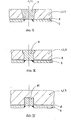
- the innovation is described in more detail by way of example with the aid of schematic illustrations I to IV.
- a shielding container (6) contains a transport and / or storage container, consisting of a base body (1) with a base (2) and cover (3) made of an inexpensive metallic material.
- the storage container contains radioactive material (7), for example irradiated fuel elements from nuclear reactors or radioactive waste from reprocessing plants.
- Base body (1), bottom (2) and cover (3) are surrounded by a gas-tight jacket (4) made of corrosion-resistant metallic material.
- the jacket (4) lies relatively tight on the storage container. Therefore, the gap (8) located between the jacket (4) and the base body (1) or base (2) and cover (3) is very small. It can be filled with helium or another gas to test the tightness of weld seams in the jacket (4) and in the lid or bottom area.
- the jacket (4) is connected to the base body (1) including the cover and base area via anchors (5).
- the number and distribution of the anchors (5) is adapted to the respective design needs.
- the anchors (5) are advantageously made of the same material as the jacket (4) and fix the jacket (4), the thickness of which is dimensioned in a material-saving manner only with regard to the possibly expected maximum corrosion attack, against bulging when the internal pressure increases due to the heat producing radioactive inventory arises.
- conical anchors (9) - Fig. II - can be used or bolt-shaped anchors (10) - Fig. III - which ver with one or more shoulders are seen.
- such anchors (9, 10) penetrate the base body (1).
- the anchors are screwed into the base body (1) as screw anchors (11) - FIG. IV - since in this way the base body (1) does not have to be drilled through.
- the same is the case if the anchors (5) are inserted into the base body from the outside in the manner of an expansion dowel or a bayonet holder.
- the corrosion-resistant jacket (4) is fastened to the anchors (5) embedded in the base body (1), for example by soldering or riveting. It has been found that welding the armature (5) to the jacket (4) is particularly favorable.
- the outside of the anchor can either be flush with the outer surface of the jacket or set back. If necessary, it is also possible to screw the anchor (5) and the jacket (4) together.
- the anchor (5) can also be composed of several materials if this results in fastening advantages in the base body.
Landscapes
- Physics & Mathematics (AREA)
- Engineering & Computer Science (AREA)
- General Engineering & Computer Science (AREA)
- High Energy & Nuclear Physics (AREA)
- Filling Or Discharging Of Gas Storage Vessels (AREA)
- Packages (AREA)
Abstract
Description
- Gegenstand der vorliegenden Erfindung ist ein Transport-und/oder Lagerbehälter für Warme produzierende radioaktive Stoffe, bestehend aus einem Grundkörper und einem diesen Grundkörper in einem Abstand allseitig umschließenden gasdichten Mantel aus korrosionsfestem Material.
- Für den Transport und die Lagerung Wärme produzierender radioaktive Stoffe, wie z.B. abgebrannte Brennelemente aus Kernkraftwerken oder Abfälle aus Anlagen zur Wiederaufarbeitung abgebrannter Brennelemente, werden Behälter verwendet, in denen die radioaktiven Stoffe sicher eingeschlossen sind, aus denen die erzeugte Wärme jederzeit sicher abgeführt werden kann und die kritisch sicher sind.
- Üblicherweise werden dickwandige Behälter benutzt, die zum Teil innen mit Edelstahl ausgekleidet sind. Sollen die Behälter unter Tage, z.B. in stillgelegten Bergwerken, gelagert werden, müssen die Behälterwandungen die gebirgsmechanischen Kräfte aufnehmen können und korrosionsfest sein.
- Aus Gründen der Wirtschaftlichkeit werden in solchen Fällen mehrschichtige Behälter verwendet. Für den Grundkörper wird ein wärmebeständiger, preiswerter Werkstoff verwendet, der nicht korrosionsbeständig sein muß, da er nicht mit korrosiven Medien in Berührung kommt. Der Behälter wird so dimensioniert, daß er dem Gebirgsdruck standhält. Er muß nicht dicht sein, so daß der Boden und der Deckel eingesetzt oder eingeschraubt sein kann.
- Als Werkstoffe für den Grundkörper kommen z.B. geeignete wärmebeständige Feinkornstähle in Frage. Neben metallischen Materialien können aber auch Betonbehälter als Grundkörper zum Einsatz kommen.
- Für die Außenschicht bzw. den Außenmantel der Behälter werden korrosionsbeständige Werkstoffe verwendet. In Frage kommen in Salzbergwerken, in denen das Auftreten quinärer Laugen zumindest theoretisch in Betracht gezogen werden muß, hochlegierte Stähle, wie z.B. Hastelloy, oder Stähle auf Zirkon- oder Titanbasis.
- Die Dicke dieser Bleche wird dabei so gewählt, daß sie der zu erwartenden Korrosion für die Dauer der Lagerung widersteht und, da der"Grundkörper nicht gasdicht ist, dem Innendruck standhält. Dieser Innendruck baut sich nach der Beladung des Behälters infolge Aufheizung durch das Wärme produzierende radioaktive Inventar auf.
- Der sich maximal aufbauende Innendruck ist für die Auslegung der Dicke des Außenmantels bestimmend, d.h. wegen des Innendruckes muß der Korrosionsschutzmantel erheblich dicker dimensioniert werden, als es an und für sich aus Gründen des Korrosionsschutzes und der Dichtheit allein notwendig wäre. Dies gilt insbesondere für ebene Böden und Deckel, die bei den in Betracht zu ziehenden Abmessungen noch überproportional dicker sein müssen als die zylindrischen Mäntel sonst üblicher Transport- und Lagerbehälter.
- Da das Material für den Korrosionsschutzmantel außerordentlich teuer ist sind derartige Ausführungen sehr aufwendig. Darüberhinaus ist es fertigungstechnisch schwierig, die Bleche des Korrosionsschutzmantels so mit den dickeren Boden- und Deckelblechen zu verbinden, daß Stabilität und Dichtheit sichergestellt sind.
- Der Erfindunglag daher die Aufgabe zugrunde, einen Transport- und/oder Lagerbehälter für Wärme produzierende radioaktive Stoffe zu schaffen, bestehend aus einem Grundkörper und einem diesen Grundkörper in einem Abstand allseitig umschließenden gasdichten Mantel aus korrosionsfestem Material, bei dem die Dicke des gasdichten Mantels nur auf Korrosionsfestigkeit ausgelegt ist, einfach herstellbar und prüfbar ist.
- Diese Aufgabe wurde erfindungsgemäß dadurch gelöst, daß der Mantel über Anker mit dem Grundkörper verbunden ist.
- In besonders vorteilhaften Ausgestaltungen sind die Anker einerseits in den Grundkörper eingeschraubt und andererseits mit dem Mantel verschweißt. Es ist dabei günstig, wenn Anker und Mantel aus gleichem Material bestehen. Anhand der schematischen Abbildungen I bis IV ist die Neuerung beispielhaft näher beschrieben.
- In einem Abschirmbehälter (6) befindet sich ein Transport-und/oder Lagerbehälter, bestehend aus einem Grundkörper (1) mit Boden (2) und Deckel (3) aus einem preiswerten metallischen Werkstoff. Der Lagerbehälter enthält radioaktives Material (7), beispielsweise bestrahlte Brennelemente aus Kernreaktoren oder radioaktive Abfälle aus Wiederaufarbeitungsanlagen. Grundkörper (1), Boden (2) und Deckel (3) sind von einem gasdichten Mantel (4) aus korrosionsfestem metallischen Material umgeben. Der Mantel (4) liegt verhältnismäßig dicht auf dem Lagerbehälter an. Daher ist der zwischen dem Mantel (4) und dem Grundkörper (1) bzw. Boden (2) und Deckel (3) befindliche Spalt (8) sehr klein. Er kann mit Helium oder einem anderen Gas zur Prüfung der Dichtheit von Schweißnähten im Mantel (4) und im Deckel-oder Bodenbereich gefüllt sein. Der Mantel (4) ist mit dem Grundkörper (1) einschließlich Deckel- und Bodenbereich über Anker (5) verbunden. Die Anzahl und Verteilung der Anker (5) ist den jeweiligen Auslegungsbedürfnissen angepaßt. Die Anker (5) sind vorteilhafterweise aus dem gleichen Material wie der Mantel (4) gefertigt und fixieren den Mantel (4), dessen Dicke materialsparend lediglich hinsichtlich dem möglicherweise erwartenden maximalen Korrosionsangriff dimensioniert ist, gegen Aufbeulen bei sich erhöhendem Innendruck, der durch das Wärme produzierende radioaktive Inventar entsteht. Es können hierbei konische Anker (9) - Abb. II - verwendet werden oder aber bolzenförmige Anker (10) - Abb. III -, die mit einem oder mehreren Absätzen versehen sind. Derartige Anker (9, 10) durchdringen aber den Grundkörper (1). Daher ist es besonders günstig, wenn die Anker als Schraubanker (11) - Abb. IV - in den Grundkörper (1) eingeschraubt werden, da auf diese Weise der Grundkörper (1) nicht durchbohrt werden muß. Gleiches ist der Fall, wenn die Anker (5) in der Art eines Spreizdübels oder einer Bajonetthalterung von außen in den Grundkörper eingelassen werden. An den so in den Grundkörper (1) eingelassenen Ankern (5) wird der korrosionsfeste Mantel (4) befestigt, z.B. durch Löten oder Nieten. Es hat sich herausgestellt, daß das Verschweißen des Ankers (5) mit dem Mantel (4) besonders günstig ist.
- Je nach den Erfordernissen kann die Ankeraußenseite mit der äußeren Manteloberfläche entweder bündig abschließen oder aber zurückgesetzt sein. Gegebenenfalls ist es auch möglich, Anker (5) und Mantel (4) miteinander zu verschrauben._Der Anker (5) kann auch aus mehreren Materialien zusammengesetzt sein, falls sich dadurch Befestigungsvorteile im Grundkörper ergeben.
- Mit der vorliegenden Erfindungist es überraschend möglich, die Dicke des Korrosionsmantels material- und kostensparend auch unter dem Aspekt eines sich aufbauenden Innendruckes auf die tatsächlichen Erfordernisse hin zu minimieren. Die Montage der Anker und des Mantels auf den Ankern ist einfach, metallische Verbindungsprobleme .bestehen bei geeigneter Wahl der Metallkombinationen nicht. Zudem sind alle Schweißnähte oder andere Verbindungsarten einwandfrei prüfbar.
Claims (4)
Applications Claiming Priority (2)
| Application Number | Priority Date | Filing Date | Title |
|---|---|---|---|
| DE8233960U | 1982-12-03 | ||
| DE19828233960U DE8233960U1 (de) | 1982-12-03 | 1982-12-03 | Transport- und/oder lagerbehaelter fuer waermeproduzierende radioaktive stoffe |
Publications (2)
| Publication Number | Publication Date |
|---|---|
| EP0111231A1 true EP0111231A1 (de) | 1984-06-20 |
| EP0111231B1 EP0111231B1 (de) | 1987-03-18 |
Family
ID=6746173
Family Applications (1)
| Application Number | Title | Priority Date | Filing Date |
|---|---|---|---|
| EP83111851A Expired EP0111231B1 (de) | 1982-12-03 | 1983-11-26 | Transport- und/oder Lagerbehälter für wärmeproduzierende radioaktive Stoffe |
Country Status (6)
| Country | Link |
|---|---|
| EP (1) | EP0111231B1 (de) |
| JP (1) | JPS59150393A (de) |
| BR (1) | BR8306562A (de) |
| CA (1) | CA1220568A (de) |
| DE (2) | DE8233960U1 (de) |
| ES (1) | ES293235Y (de) |
Cited By (2)
| Publication number | Priority date | Publication date | Assignee | Title |
|---|---|---|---|---|
| DE3413393A1 (de) * | 1984-04-10 | 1985-10-17 | Transnuklear Gmbh, 6450 Hanau | Einsatzkorb fuer transport- und lagerbehaelter |
| GB2171632A (en) * | 1984-12-22 | 1986-09-03 | Kernforschungsz Karlsruhe | Containment with long-time corrosion resistant cover for sealed containers with highly radio-active content |
Citations (4)
| Publication number | Priority date | Publication date | Assignee | Title |
|---|---|---|---|---|
| BE713125A (de) * | 1968-04-02 | 1968-08-16 | ||
| DE1514389A1 (de) * | 1965-01-27 | 1969-07-17 | Siemens Ag | Transportbehaelter fuer verbrauchte Brennelemente von Kernreaktoren |
| DE1514623A1 (de) * | 1965-11-22 | 1970-03-05 | Siemens Ag | Transportbehaelter fuer verbrauchte Brennelemente von Kernreaktoren |
| FR2113805A1 (de) * | 1970-11-17 | 1972-06-30 | Transnucleaire |
-
1982
- 1982-12-03 DE DE19828233960U patent/DE8233960U1/de not_active Expired
-
1983
- 1983-11-26 DE DE8383111851T patent/DE3370397D1/de not_active Expired
- 1983-11-26 EP EP83111851A patent/EP0111231B1/de not_active Expired
- 1983-11-29 BR BR8306562A patent/BR8306562A/pt unknown
- 1983-12-02 CA CA000442473A patent/CA1220568A/en not_active Expired
- 1983-12-02 ES ES1983293235U patent/ES293235Y/es not_active Expired
- 1983-12-02 JP JP58227104A patent/JPS59150393A/ja active Pending
Patent Citations (4)
| Publication number | Priority date | Publication date | Assignee | Title |
|---|---|---|---|---|
| DE1514389A1 (de) * | 1965-01-27 | 1969-07-17 | Siemens Ag | Transportbehaelter fuer verbrauchte Brennelemente von Kernreaktoren |
| DE1514623A1 (de) * | 1965-11-22 | 1970-03-05 | Siemens Ag | Transportbehaelter fuer verbrauchte Brennelemente von Kernreaktoren |
| BE713125A (de) * | 1968-04-02 | 1968-08-16 | ||
| FR2113805A1 (de) * | 1970-11-17 | 1972-06-30 | Transnucleaire |
Non-Patent Citations (1)
| Title |
|---|
| ISOTOPES AND RADIATION TECHNOLOGY, Band 8, Nr. 3, Frühling 1971, Seiten 350-359, Oak Ridge, US * |
Cited By (4)
| Publication number | Priority date | Publication date | Assignee | Title |
|---|---|---|---|---|
| DE3413393A1 (de) * | 1984-04-10 | 1985-10-17 | Transnuklear Gmbh, 6450 Hanau | Einsatzkorb fuer transport- und lagerbehaelter |
| GB2171632A (en) * | 1984-12-22 | 1986-09-03 | Kernforschungsz Karlsruhe | Containment with long-time corrosion resistant cover for sealed containers with highly radio-active content |
| US4702391A (en) * | 1984-12-22 | 1987-10-27 | Kernforschungszentrum Karlsruhe Gmbh | Containment with long-time corrosion resistant cover for sealed containers with highly radioactive content |
| GB2171632B (en) * | 1984-12-22 | 1989-06-07 | Kernforschungsz Karlsruhe | Long term corrosion-resistant covering structure for sealed containers having a highly radioactive content. |
Also Published As
| Publication number | Publication date |
|---|---|
| ES293235Y (es) | 1987-04-01 |
| JPS59150393A (ja) | 1984-08-28 |
| ES293235U (es) | 1986-07-01 |
| BR8306562A (pt) | 1984-07-31 |
| DE3370397D1 (en) | 1987-04-23 |
| EP0111231B1 (de) | 1987-03-18 |
| CA1220568A (en) | 1987-04-14 |
| DE8233960U1 (de) | 1983-06-16 |
Similar Documents
| Publication | Publication Date | Title |
|---|---|---|
| DE2915376C2 (de) | Behälterkombination für den Transport und die Lagerung bestrahlter Brennelemente aus Kernreaktoren | |
| DE69400946T2 (de) | Behälter zum Transport von radioaktiven Stoffen | |
| DE2839759A1 (de) | Verschluss von lagerbohrungen zur endlagerung radioaktiver abfaelle und verfahren zum anbringen des verschlusses | |
| DE2905094A1 (de) | Abschirmtransport- und/oder abschirmlagerbehaelter | |
| DE2821780A1 (de) | Transport- und lagereinrichtung fuer radioaktive stoffe | |
| CH631407A5 (de) | Abschirmbehaelter zum transportieren und/oder lagern von radioaktiven abfaellen. | |
| DE2418518A1 (de) | Speichervorrichtung fuer radioaktiven abfall | |
| EP0092679B1 (de) | Behälter zur Aufnahme von radioaktiven Stoffen | |
| DE3331892C2 (de) | Transport- und Lagerbehälter für radioaktives Material | |
| DE2726335A1 (de) | Endlagerbehaelter fuer radioaktive abfaelle | |
| CH639794A5 (de) | Abschirmbehaelter fuer den transport und/oder die lagerung bioschaedlicher abfaelle, insbesondere bestrahlter brennelemente. | |
| DE3026249A1 (de) | Transport- und/oder lagerbehaelter fuer radioaktive stoffe | |
| EP0057429B1 (de) | Mehrschichtiger Transport- und Lagerbehälter für radioaktive Abfälle | |
| EP0115028B1 (de) | Lagerbehälter für radioaktives Material | |
| EP0111231B1 (de) | Transport- und/oder Lagerbehälter für wärmeproduzierende radioaktive Stoffe | |
| EP0057867A1 (de) | Mehrschichtiger Behälter zur sicheren Langzeitlagerung von radioaktivem Material | |
| DE3125211A1 (de) | Lagerbehaelter und verfahren zu seiner herstellung | |
| EP1978530B1 (de) | Behältersystem zur Aufnahme radioaktiver Abfälle | |
| DE2726206A1 (de) | Verfahren zur zerlegung dickwandiger stahlbehaelter | |
| DE1257299B (de) | Transportbehaelter fuer radioaktive Materialien | |
| DE2837631A1 (de) | Transportabschirm- und/oder lagerabschirmbehaelter | |
| DE2804828A1 (de) | Stahlbehaelter zur aufnahme abgebrannter brennelemente | |
| DE2745408A1 (de) | Verfahren zum zerlegen starkwandiger behaeltnisse, insbesondere solcher, die radioaktiv verseucht sind | |
| DE2952168C2 (de) | Transport- und/oder Lagerbehälter für radioaktive Stoffe | |
| EP0978849B1 (de) | Endlagerbehälter für abgebrannte Brennelemente aus Kernkraftwerken |
Legal Events
| Date | Code | Title | Description |
|---|---|---|---|
| PUAI | Public reference made under article 153(3) epc to a published international application that has entered the european phase |
Free format text: ORIGINAL CODE: 0009012 |
|
| 17P | Request for examination filed |
Effective date: 19831126 |
|
| AK | Designated contracting states |
Designated state(s): BE CH DE FR GB LI SE |
|
| GRAA | (expected) grant |
Free format text: ORIGINAL CODE: 0009210 |
|
| AK | Designated contracting states |
Kind code of ref document: B1 Designated state(s): BE CH DE FR GB LI SE |
|
| REF | Corresponds to: |
Ref document number: 3370397 Country of ref document: DE Date of ref document: 19870423 |
|
| ET | Fr: translation filed | ||
| PG25 | Lapsed in a contracting state [announced via postgrant information from national office to epo] |
Ref country code: SE Effective date: 19871127 |
|
| PG25 | Lapsed in a contracting state [announced via postgrant information from national office to epo] |
Ref country code: LI Effective date: 19871130 Ref country code: CH Effective date: 19871130 Ref country code: BE Effective date: 19871130 |
|
| PLBE | No opposition filed within time limit |
Free format text: ORIGINAL CODE: 0009261 |
|
| STAA | Information on the status of an ep patent application or granted ep patent |
Free format text: STATUS: NO OPPOSITION FILED WITHIN TIME LIMIT |
|
| 26N | No opposition filed | ||
| BERE | Be: lapsed |
Owner name: DEUTSCHE GESELLSCHAFT FUR WIEDERAUFARBEITUNG VON K Effective date: 19871130 Owner name: NUKEM GMBH Effective date: 19871130 |
|
| GBPC | Gb: european patent ceased through non-payment of renewal fee | ||
| PG25 | Lapsed in a contracting state [announced via postgrant information from national office to epo] |
Ref country code: FR Free format text: LAPSE BECAUSE OF NON-PAYMENT OF DUE FEES Effective date: 19880729 |
|
| REG | Reference to a national code |
Ref country code: CH Ref legal event code: PL |
|
| PG25 | Lapsed in a contracting state [announced via postgrant information from national office to epo] |
Ref country code: DE Effective date: 19880802 |
|
| REG | Reference to a national code |
Ref country code: FR Ref legal event code: ST |
|
| PG25 | Lapsed in a contracting state [announced via postgrant information from national office to epo] |
Ref country code: GB Effective date: 19881122 |
|
| EUG | Se: european patent has lapsed |
Ref document number: 83111851.8 Effective date: 19880913 |