EP0111012B1 - Rauchsensor des ionisationstyps - Google Patents
Rauchsensor des ionisationstyps Download PDFInfo
- Publication number
- EP0111012B1 EP0111012B1 EP83901734A EP83901734A EP0111012B1 EP 0111012 B1 EP0111012 B1 EP 0111012B1 EP 83901734 A EP83901734 A EP 83901734A EP 83901734 A EP83901734 A EP 83901734A EP 0111012 B1 EP0111012 B1 EP 0111012B1
- Authority
- EP
- European Patent Office
- Prior art keywords
- ionization
- electrode
- smoke
- radioactive source
- source
- Prior art date
- Legal status (The legal status is an assumption and is not a legal conclusion. Google has not performed a legal analysis and makes no representation as to the accuracy of the status listed.)
- Expired
Links
Images
Classifications
-
- G—PHYSICS
- G08—SIGNALLING
- G08B—SIGNALLING SYSTEMS, e.g. PERSONAL CALLING SYSTEMS; ORDER TELEGRAPHS; ALARM SYSTEMS
- G08B17/00—Fire alarms; Alarms responsive to explosion
- G08B17/10—Actuation by presence of smoke or gases, e.g. automatic alarm devices for analysing flowing fluid materials by the use of optical means
- G08B17/11—Actuation by presence of smoke or gases, e.g. automatic alarm devices for analysing flowing fluid materials by the use of optical means using an ionisation chamber for detecting smoke or gas
- G08B17/113—Constructional details
Definitions
- the present invention relates to an ionization smoke detector with a single radioactive source according to the preamble of claim 1.
- the ionization smoke detectors known to date can be divided into two categories: 1) smoke detectors with two radioactive sources and an outer measurement ionization chamber that is freely accessible to the smoke, and an inner comparison or reference ionization chamber that is not accessible to the smoke, whereby each chamber has a radioactive source, and 2) in smoke detectors with a single radioactive source and an intermediate electrode which divides the two ionization chambers and which has a small passage. Opening contains for the irradiation of the outer ionization chamber by the radioactive source arranged in the inner ionization chamber.
- the smoke detector with a radioactive source has advantages over the two-source smoke detector because of its simple construction and its lower radiation energy requirement.
- GB-A-2 013 393 describes such a smoke detector with a radioactive source for both ionization chambers.
- the radioactive source is arranged in the inner ionization chamber and is exposed to contamination by the smoke particles entering the inner ionization chamber.
- a cover plate was placed over it, which has an opening for the desired passage of the radioactive radiation for ionizing the inner and outer ionization chamber.
- the size of the opening is a compromise between the desired ionization of the two chambers and the undesirable contamination of the radioactive source and can never be optimal. Either ionization and pollution are large or small at the same time. In no case is the ionization large and the pollution small. This did not solve the problem of preventing pollution.
- US-A-3935466 shows a smoke detector with a radioactive source for both ionization chambers.
- the radioactive source can be located within the inner or outer ionization chamber.
- the size of the opening required for the passage of the ionization rays into both chambers is only dependent on the desired amount of the rays, since the influence of the contamination of the radioactive source on the sensitivity was not known.
- the object of the invention is to provide an ionization smoke detector with a single radioactive source, in which this contamination of the source is eliminated and the smoke is quickly dispersed after the operational test has been completed. This quickly brings the smoke detector back to its initial or normal state.
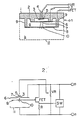
- FIGS. 1 and 2 show an exemplary embodiment.
- Figure 1 shows an ionization smoke detector in cross section and Figure 2 shows the electrical circuit for this detector.
- the inner ionization chamber a, the outer ionization chamber b, substrate 1, annular wall 2, radioactive source 3, inner electrode 6, openings 7, 10, intermediate electrode 8, and the outer electrode 11 are shown.
- An annular wall 2 is provided on the substrate 1.
- a radioactive source 3 is arranged on an electrode 5, the vertical position of which can be adjusted by means of a screw 4.
- a disc-shaped inner electrode 6 is arranged on the annular wall 2.
- a disc-like intermediate electrode 8 is provided which is supported by a plurality of webs 9 and in the middle of which an opening 10 is provided.
- a grid-shaped outer electrode 11 is attached to the substrate and surrounds the electrodes 6 and 8.
- the inner ionization chamber a is formed by the inner electrode 6 and the intermediate electrode 8.
- the outer ionization chamber b is delimited by the intermediate electrode 8 and the outer electrode 11.
- the radioactive source 3 sends its radiation into the ionization chamber a, b, specifically through the openings 7, 10, which are coaxial with the source 3. As a result, the air is ionized in the two chambers a and b.
- the inner electrode 6 is electrically connected to the positive terminal p and the outer electrode 11 to the negative terminal n of the detector.
- the intermediate electrode 8 is connected to the gate electrode of an FET located between the terminals p, n and via a resistor R.
- the electrode 5 is at the tap of a change union resistor VR connected between terminals p and n.
- the source electrode of the FET is on a circuit SW, which is connected between the terminals p and n.
- the inner ionization chamber a has such a voltage that the ionization current flowing in it is in the saturation range.
- the operation of the smoke detector is described below.
- the dust-carrying air moves evenly into the ionization chambers a, b and out of the ionization chambers again, depending on the air flow prevailing in the room in which the smoke detector is installed.
- This is made possible because the intermediate electrode 8 is only supported by a plurality of webs 9. Because the inner electrode 6 and the annular wall 2 cover the radioactive source 3, the source is protected from the air flow and remains in a clean state despite the opening 7 in the inner electrode 6.
- the ionization current flowing in the outer ionization chamber b decreases. This increases the gate potential of the FET that operates the fire alarm display circuit SW when it reaches a predetermined voltage.
- a smoke generator supplies the necessary smoke to test the smoke detector. If the smoke generator is removed from the detector at the end of the test process, the smoke present in ionization chambers a and b is quickly removed. This rapid removal of the smoke takes place through the air circulation in the room because the two ionization chambers are freely accessible to the air. The smoke detector is quickly returned to its normal working state at the end of the test.
- the potential of the intermediate electrode 8 is changed accordingly, so that the sensitivity of the smoke detector can be adjusted.
- the radioactive source can be satisfactorily protected against contamination.
- the smoke detector is quickly cleared of any smoke after the end of an operational test and is therefore returned to its initial or normal state within a short time.
- This single-source ionization smoke detector has several advantages over the prior art.
Landscapes
- Chemical & Material Sciences (AREA)
- Analytical Chemistry (AREA)
- Business, Economics & Management (AREA)
- Emergency Management (AREA)
- Physics & Mathematics (AREA)
- General Physics & Mathematics (AREA)
- Fire-Detection Mechanisms (AREA)
- Other Investigation Or Analysis Of Materials By Electrical Means (AREA)
Applications Claiming Priority (2)
| Application Number | Priority Date | Filing Date | Title |
|---|---|---|---|
| JP83510/82U | 1982-06-07 | ||
| JP1982083510U JPS58186463U (ja) | 1982-06-07 | 1982-06-07 | イオン化式煙感知器 |
Publications (3)
| Publication Number | Publication Date |
|---|---|
| EP0111012A1 EP0111012A1 (de) | 1984-06-20 |
| EP0111012A4 EP0111012A4 (de) | 1984-12-11 |
| EP0111012B1 true EP0111012B1 (de) | 1989-08-09 |
Family
ID=13804477
Family Applications (1)
| Application Number | Title | Priority Date | Filing Date |
|---|---|---|---|
| EP83901734A Expired EP0111012B1 (de) | 1982-06-07 | 1983-06-07 | Rauchsensor des ionisationstyps |
Country Status (5)
| Country | Link |
|---|---|
| US (1) | US4594512A (enExample) |
| EP (1) | EP0111012B1 (enExample) |
| JP (1) | JPS58186463U (enExample) |
| DE (1) | DE3380374D1 (enExample) |
| WO (1) | WO1983004449A1 (enExample) |
Families Citing this family (7)
| Publication number | Priority date | Publication date | Assignee | Title |
|---|---|---|---|---|
| JPS6044194U (ja) * | 1983-09-05 | 1985-03-28 | 能美防災工業株式会社 | イオン化式煙感知器の耐熱ケ−ス |
| US4761557A (en) * | 1985-08-24 | 1988-08-02 | Kohmi Bosai Kogyo Co., Ltd. | Ionization-type smoke detector |
| CA1267735A (en) * | 1986-01-17 | 1990-04-10 | Nohmi Bosai Kogyo Co., Ltd. | Ionization type-smoke detector |
| FR2594953B1 (fr) * | 1986-02-25 | 1989-05-05 | Lewiner Jacques | Detecteur de fumee a chambre d'ionisation |
| DE3921377A1 (de) * | 1989-06-29 | 1991-01-03 | Inotech Ag Wohlen | Vorrichtung und verfahren zum messen von elektronen |
| US5485144A (en) * | 1993-05-07 | 1996-01-16 | Pittway Corporation | Compensated ionization sensor |
| US20030180591A1 (en) * | 2001-03-29 | 2003-09-25 | Steven Danyluk | Contact potential difference ionization battery |
Family Cites Families (8)
| Publication number | Priority date | Publication date | Assignee | Title |
|---|---|---|---|---|
| USRE30323E (en) * | 1968-09-26 | 1980-07-01 | Hochiki Kabushiki Kaisha | Smoke detector adapted to a smoke sensing apparatus |
| GB1280304A (en) * | 1968-09-26 | 1972-07-05 | Hochiki Co | A smoke sensing detector for smoke sensing apparatus |
| GB2010578B (en) * | 1977-11-18 | 1982-09-15 | Radiochemical Centre Ltd | Smoke detectors |
| GB2013393B (en) * | 1977-11-18 | 1982-03-03 | Radiochemical Centre Ltd | Smoke detectors |
| CA1116319A (en) * | 1977-11-18 | 1982-01-12 | Jack Bryant | Smoke detectors |
| CA1115860A (en) * | 1977-11-18 | 1982-01-05 | Dennis W.S. Smout | Smoke detectors |
| JPS5821031Y2 (ja) * | 1978-03-15 | 1983-05-02 | ホーチキ株式会社 | 煙感知器 |
| JPS5759965Y2 (enExample) * | 1978-04-25 | 1982-12-21 |
-
1982
- 1982-06-07 JP JP1982083510U patent/JPS58186463U/ja active Granted
-
1983
- 1983-06-07 WO PCT/JP1983/000187 patent/WO1983004449A1/ja not_active Ceased
- 1983-06-07 US US06/573,923 patent/US4594512A/en not_active Expired - Lifetime
- 1983-06-07 EP EP83901734A patent/EP0111012B1/de not_active Expired
- 1983-06-07 DE DE8383901734T patent/DE3380374D1/de not_active Expired
Also Published As
| Publication number | Publication date |
|---|---|
| US4594512A (en) | 1986-06-10 |
| EP0111012A1 (de) | 1984-06-20 |
| JPS58186463U (ja) | 1983-12-10 |
| EP0111012A4 (de) | 1984-12-11 |
| DE3380374D1 (en) | 1989-09-14 |
| WO1983004449A1 (fr) | 1983-12-22 |
| JPH029430Y2 (enExample) | 1990-03-08 |
Similar Documents
| Publication | Publication Date | Title |
|---|---|---|
| DE2652970C3 (de) | Ionisations-Brandmelder | |
| DE1089193B (de) | Gasanalyse- und Gaswarngeraet und Ionisationskammer fuer dieses Geraet | |
| EP0127645B1 (de) | Brandmelder und dafür bestimmte elektrodenanordnung | |
| DE2415479C3 (de) | Ionisationsbrandmelder | |
| DE2023954C3 (de) | Ionisationsfeuermelder | |
| DE1648902B2 (de) | Ionenkammerdetektor | |
| DE2462539C2 (de) | Elektrischer Staubabscheider | |
| EP0111012B1 (de) | Rauchsensor des ionisationstyps | |
| DE2738918C3 (de) | Ionisationskammer mit zwei Meßkammern | |
| DE2603373A1 (de) | Ionisationsdetektor | |
| DE4320607C2 (de) | Anordnung zur Spurengasanalyse | |
| DE69727301T2 (de) | Driftzelle | |
| EP0030621B1 (de) | Ionisationsrauchmelder mit erhöhter Betriebssicherheit | |
| DE2364034C3 (de) | Überspannungsableiter | |
| DE8337787U1 (de) | Jonisation-rauchmelder | |
| DE2546970C3 (de) | Ionisations-Rauchmelder | |
| DE1616020B2 (de) | Feuermeldevorrichtung | |
| DE2631241B2 (de) | Rauchdetektor | |
| DE1014759B (de) | Gasdruckmessvorrichtung | |
| DE4016231C2 (de) | Ionisations-Rauchdetektor | |
| CH572644A5 (en) | Ionisation chamber fire detector - with threshold cct. monitoring ionisation current connected to switch cct. for further chamber | |
| DE1101370B (de) | Einrichtung zur elektrischen Beladung von in einem Luftstrom suspendierten Partikeln mittels radioaktiver Praeparate | |
| DE3010739C2 (de) | Flüssigkeitsstandfühler | |
| DE2711457C2 (de) | Ionisationsbrandmelder | |
| DE3200620A1 (de) | Ionisations-rauchdetektor |
Legal Events
| Date | Code | Title | Description |
|---|---|---|---|
| PUAI | Public reference made under article 153(3) epc to a published international application that has entered the european phase |
Free format text: ORIGINAL CODE: 0009012 |
|
| AK | Designated contracting states |
Designated state(s): BE CH DE FR GB LI |
|
| 17P | Request for examination filed |
Effective date: 19840124 |
|
| 17Q | First examination report despatched |
Effective date: 19870909 |
|
| GRAA | (expected) grant |
Free format text: ORIGINAL CODE: 0009210 |
|
| AK | Designated contracting states |
Kind code of ref document: B1 Designated state(s): BE CH DE FR GB LI |
|
| PG25 | Lapsed in a contracting state [announced via postgrant information from national office to epo] |
Ref country code: BE Effective date: 19890809 |
|
| REF | Corresponds to: |
Ref document number: 3380374 Country of ref document: DE Date of ref document: 19890914 |
|
| GBT | Gb: translation of ep patent filed (gb section 77(6)(a)/1977) | ||
| ET | Fr: translation filed | ||
| PLBE | No opposition filed within time limit |
Free format text: ORIGINAL CODE: 0009261 |
|
| STAA | Information on the status of an ep patent application or granted ep patent |
Free format text: STATUS: NO OPPOSITION FILED WITHIN TIME LIMIT |
|
| 26N | No opposition filed | ||
| REG | Reference to a national code |
Ref country code: CH Ref legal event code: PFA Free format text: NOHMI BOSAI LTD |
|
| PGFP | Annual fee paid to national office [announced via postgrant information from national office to epo] |
Ref country code: FR Payment date: 19950510 Year of fee payment: 13 |
|
| PGFP | Annual fee paid to national office [announced via postgrant information from national office to epo] |
Ref country code: GB Payment date: 19950512 Year of fee payment: 13 |
|
| PGFP | Annual fee paid to national office [announced via postgrant information from national office to epo] |
Ref country code: DE Payment date: 19950529 Year of fee payment: 13 |
|
| PG25 | Lapsed in a contracting state [announced via postgrant information from national office to epo] |
Ref country code: GB Effective date: 19960607 |
|
| PGFP | Annual fee paid to national office [announced via postgrant information from national office to epo] |
Ref country code: CH Payment date: 19960826 Year of fee payment: 14 |
|
| GBPC | Gb: european patent ceased through non-payment of renewal fee |
Effective date: 19960607 |
|
| PG25 | Lapsed in a contracting state [announced via postgrant information from national office to epo] |
Ref country code: FR Effective date: 19970228 |
|
| PG25 | Lapsed in a contracting state [announced via postgrant information from national office to epo] |
Ref country code: DE Effective date: 19970301 |
|
| REG | Reference to a national code |
Ref country code: FR Ref legal event code: ST |
|
| PG25 | Lapsed in a contracting state [announced via postgrant information from national office to epo] |
Ref country code: LI Free format text: LAPSE BECAUSE OF NON-PAYMENT OF DUE FEES Effective date: 19970630 Ref country code: CH Free format text: LAPSE BECAUSE OF NON-PAYMENT OF DUE FEES Effective date: 19970630 |
|
| REG | Reference to a national code |
Ref country code: CH Ref legal event code: PL |