EP0109711A2 - Gerät für plattenförmige Aufzeichnungsträger - Google Patents
Gerät für plattenförmige Aufzeichnungsträger Download PDFInfo
- Publication number
- EP0109711A2 EP0109711A2 EP83201623A EP83201623A EP0109711A2 EP 0109711 A2 EP0109711 A2 EP 0109711A2 EP 83201623 A EP83201623 A EP 83201623A EP 83201623 A EP83201623 A EP 83201623A EP 0109711 A2 EP0109711 A2 EP 0109711A2
- Authority
- EP
- European Patent Office
- Prior art keywords
- disc
- guide
- loading
- slots
- loading support
- Prior art date
- Legal status (The legal status is an assumption and is not a legal conclusion. Google has not performed a legal analysis and makes no representation as to the accuracy of the status listed.)
- Granted
Links
Images


Classifications
-
- G—PHYSICS
- G11—INFORMATION STORAGE
- G11B—INFORMATION STORAGE BASED ON RELATIVE MOVEMENT BETWEEN RECORD CARRIER AND TRANSDUCER
- G11B17/00—Guiding record carriers not specifically of filamentary or web form, or of supports therefor
- G11B17/02—Details
- G11B17/04—Feeding or guiding single record carrier to or from transducer unit
- G11B17/05—Feeding or guiding single record carrier to or from transducer unit specially adapted for discs not contained within cartridges
- G11B17/053—Indirect insertion, i.e. with external loading means
- G11B17/056—Indirect insertion, i.e. with external loading means with sliding loading means
-
- G—PHYSICS
- G11—INFORMATION STORAGE
- G11B—INFORMATION STORAGE BASED ON RELATIVE MOVEMENT BETWEEN RECORD CARRIER AND TRANSDUCER
- G11B17/00—Guiding record carriers not specifically of filamentary or web form, or of supports therefor
- G11B17/02—Details
- G11B17/022—Positioning or locking of single discs
- G11B17/028—Positioning or locking of single discs of discs rotating during transducing operation
- G11B17/03—Positioning or locking of single discs of discs rotating during transducing operation in containers or trays
-
- G—PHYSICS
- G11—INFORMATION STORAGE
- G11B—INFORMATION STORAGE BASED ON RELATIVE MOVEMENT BETWEEN RECORD CARRIER AND TRANSDUCER
- G11B17/00—Guiding record carriers not specifically of filamentary or web form, or of supports therefor
- G11B17/22—Guiding record carriers not specifically of filamentary or web form, or of supports therefor from random access magazine of disc records
- G11B17/26—Guiding record carriers not specifically of filamentary or web form, or of supports therefor from random access magazine of disc records the magazine having a cylindrical shape with vertical axis
Definitions
- the invention relates to a record-disc player with a loading device for loading a record disc on the turntable of the player, the loading device comprising a movable loading support for supporting the disc, a guide plate fixed in a vertical plane and formed with L-shaped guide slots each comprising a horizontal section and a vertical section extending downwardly from the horizontal section at an end thereof, a drive plate supported for movement in a horizontal direction and a plane parallel to the plane of the-guide plate and formed with slots which are inclined to the direction of movement of the drive plate, the loading support comprising pins, each of which engages in an associated one of said guide slots and an associated one of said inclined slots, and a toothed rack on the drive plate and a pinion for cooperation with the rack to move the drive plate, said guide slots being arranged to guide the loading support, by cooperation with said pins, from a rest position along a horizontal path and down a vertical path to deposit the record disc supported on the loading support on the turntable, and said inclined slots being cooperable with said pins, during movement of
- a pressure member for urging the record disc into a centred position on the turntable while the turntable is rotating.
- the known record-disc player does not have such a pressure member.
- the record-disc player is characterized in that it comprises a pivoted arm carrying a pressure member for urging the loaded disc into a centred position on the turntable, the arm being pivotable between an inoperative position and an operative position about a horizontal axis perpendicular to the directions of movement of the loading support, and the arm comprising a part formed with a recess which, when the arm is in the inoperative position, is located beside and coincides with the horizontal section of one of the guide slots in the guide plate at the end of said section which adjoins the vertical section of the slot, with the mouth of the recess facing towards the other end of the horizontal section, so that when the pin on the loading support which engages in that guide slot reaches the end of the horizontal section of the slot which adjoins the vertical section during the loading movement of the loading support, the pin enters said recess, and as the pin moves down the vertical section of the slot it cooperates with the recess to move the arm to the operative position.
- a preferred embodiment of the invention is characterized in that said part of the arm comprises a plate which is pivotally supported on the guide plate for movement about said axis in a plane parallel to the plane of the guide plate, and in an edge which the recess is formed.
- the arm may be urged by spring means to its - inoperative position, which position may be determined by stop means on the guide plate.
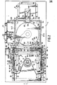
- the disc changer shown in the drawings includes a player 10 for playing optical audio discs, for example, those known as "'Compact Discs".
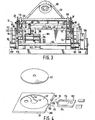
- a magazine 1 44 which contains a plurality of disc holders 38 in the form of square plates each having a shallow circular recess 40 (see Figure 4) in its upper side to receive a record disc 22.
- the disc holders 38 are supported in horizontal positions one above another in the magazine and can be slid freely into and out of the magazine.
- the magazine is carried by a device 14 which can raise and lower the magazine to bring a selected disc in its holder to a predetermined level (hereinafter referred to as the "trans- ier level") at which this holder and disc can be trans- f e rred from the magazine to a loading device 12 for loading the selected disc on the turntable 20 of the player 10.
- a small initial displacement of the holder from the magazine is effected by a device 16 located next to the magazine at the opposite side thereof from the player 10.
- the player and the devices 1 2, 14 and 1 6 are all mounted on a common base 2.
- the player 10 has a magnetic turntable with a central, upwardly protruding centering pin 24.
- the centring pin 24 has a frusto-conical centering surface 24A which engages in the centre hole 22A of the record disc which is loaded on the turntable. This locates the disc accurately on the turntable so that the disc rotates exactly concentrically with the turntable.
- Electric motors (not shown) are provided within the housing of the player 10 for driving the turntable and for tracking a read head'26 across the disc on the turntable. In known manner, the read head optically reads the pits and/or protrusions of the disc by means of a laser beam.
- the loading device 12 comprises two parallel vertical guide plates 28 and 30 which are fixed on the base 2 outside the player 10 at two opposite sides of the player and which extend in directions parallel to that in which the disc holders 38 are transferred from.the magazine 144 to the loading device.
- a movable loading support consisting of a horizontal U-shaped frame formed by two elongate side members 32 and 34 which extend parallel to the guide plates 28 and 30 and which are interconnected by a transverse member 36 (see Figure 2).
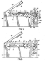
- the side members 32 and 34 have flat parts 32A and 34A respectively which lie in a'common horizontal plane for supporting a disc holder 38, as shown in Figures 6 and 7.
- the side members also have side walls at the outer edges of the parts 32A and 34A, which side walls, over at least part of the length of the.side members,project above the parts 32A and 34A and turn inwardly at the top to form guides 46 of inverted L-shaped cross-section for guiding a disc holder as it is being slid onto the parts 32A and 34A during the transference of the holder from the magazine 144 to the loading device 1 2.
- the final position of The disc holder on the loading support is determined by stops 48 which are formed by upturned positions at the ends of the parts 32A and 34A which are remote from the magazine.
- the slots 54 and 56 each comprise a horizontal section to define a horizontal path of movement for the loading support and a vertical section which extends downwardly from the horizontal section at the end thereof remote from the magazine 1 44 to define a vertical path of movement for the loading support.
- the vertical sections of the slots are so disposed that when the pins 50 and 52 are in these sections, and a disc holder 38 carrying a disc 22 is supported on the loading support, the centre hole 22A of the disc is in alignment with the centering pin 24 of the turntable 20, as shown in Figure 6.
- an arm 58 carrying a magnetic pressure ring 66 is pivotally supported between the fixed guide plates 28 and 30 of the loading device.
- the arm 58 has two cheek plates 60 which lie in planes parallel to the planes of the guide plates 28 and 30 and which are connected to the plates 28 and 30 respectively by horizontally disposed coaxial pivot pins 62 so that the arm can pivot about a horizontal axis between a raised inoperative position ( Figures 1, 3, 5, 6 and 8) and a lowered operative position ( Figure 7) in which the pressure ring 66 on the arm,under the influence of magnetic attraction between the pressure ring and the turntable 20, presses a record disc 22 against the centering surface 24A of the centering pint 24 of the turntable, as shown in Figure 7.
- the arm 58 is urged into the inoperative position by torsion springs 63 which are wrapped one around each of the pivot pins 62 and which act between abutments on the cheek plates 60 and abutments on the fixed guide plates 28 and 30.
- Pins 65 projecting from the cheek plates 60 engage slidably in arcuate slots 67 in the guide plates 28 and 30. The abutment of the pins 65 against the upper ends of the slots 67 determines the inoperative position of the arm 58.
- a recess 64 which has its mouth orientated towards the loading support 32, 34, 36.
- each of the recesses 64 is located beside and coincides with the horizontal section of the guide slot 54 in the adjacent guide plate 28 or 30 at the end of said section which adjoins the vertical section of the slot, with the mouth of the recess facing towards the other end of the horizontal section.
- the pins 50 and 52 on the tw.) side members of the loading support project beyond the_guide plates 28 and 30 to engage slidably in inclined slots 78 and 80 respectively in two movable drive plates 68 which are supported on the outer sides of the two guide plates in planes parallel to the planes of the guide plates.
- Each drive plate is supported on the adjacent guide plate 28 or 30 by two pins 74 and 76 which project from the outer side of the guide plate and engage in horizontal slots 70 and 72 respectively in the drive plate.
- the drive plates are guided by the pins 74 and 76 and slots 70 and 72 for movement in horizontal directions.
- Tension springs 69 connected one to each drive plate and the adjacent guide plate 28 or 30 urge the drive plates towards the magazine 144 to a rest position, shown in Figures 1 and 8, which is determined by the abutment of the left-hand ends (as viewed in the drawings) of the slots 70 and 72 against the pins 74 and 76.
- the inclined slots 78 and 80 in the drive plates cooperate with the pins 50 and 52 on the side members of the loading support to move the loading support first away from the magazine 1 44 along the horizontal path defined by the horizontal sections of the guide slots 54 and 56 in the guide plates 28 and 30 and then down the vertical-path defined by the vertical sections of the guide slots.
- each drive plate 68 On the lower edge of each drive plate 68 is a horizontally extending toothed rack 84, and on the outer side of each guide plate 28 and 30, for cooperation with the rack on the adjacent guide plate, is a toothed pinion 86, which is rotatable about a horizontal axis.
- the racks 84 terminate at recesses 82 in the lower edges of the drive plates, and when these plates are in the rest position the recesses 82 receive the upper parts of the toothed peripheries of the pinions 86 so that the pinions are not in mesh with the racks.
- each pinion 86 Fixed coaxially to each pinion 86 is a large gearwheel 88 which has an untoothed portion formed by a recess 92 in the periphery of the gearwheel.
- the large gearwheels 88 are arranged for cooperation with small gearwheels 90 supported one on the outer side of each of the guide plates 28 and 30.
- the gearwheels 88 When the. drive plates 68 are in the rest position ( Figures 1 and 8) the gearwheels 88 also are in a rest position in which the recesses 92 in their peripheries receive parts of the toothed peripheries of the gearwheels 90 so that the gearwheels 88 are not in mesh with the gearwheels 90.
- This rest position of the gearwheels 88 is determined by the abutment of stops 98 on these gearwheels against the lower edges of the drive plates 68, as shown in Figures 1 and 8.
- the gearwheels 88 are urged into the rest position by tension springs 96 ( Figure 1 ) which exert a rotational force on these gearwheels in the clockwise direction as viewed in the drawings.
- tension springs 96 Figure 1
- these gearwheels can be displaced from the rest position sufficiently to bring the teeth of each gearwheel in the peripheral region 94 of-the gearwheel into engagement with the teeth of the associated gearwheel 90 so that the gearwheels 88 are then in mesh with the gearwheels 90 to be driven thereby.
- each of the small gearwheels 90 Fixed coaxially to each of the small gearwheels 90 is a large gearwheel 100 ( Figures 1 and 3) which meshes with an associated further small gearwheel 102.
- the two further small gearwheels 102 are fixed on a horizontal shaft 104 which passes through the guide plates 28 and 30 and is driven by a reversible electric motor 106 mounted on the base 2.
- each pair of rubber feed rollers consisting of a drive roller 116 and above it a pressure roller 118 (see Figures . 2, 3, 5, 6 and 7).
- Each pair of feed rollers is situated adjacent an end of one of the guides 46 on the side members 32 and 34 of the loading support when the support is in the rest position.
- the two drive rollers 116 are supported on the inner sides of the guide plates 28 and 30 for rotation about a common horizontal axis and are driven by the motor 106 via gear trains arranged on the outer sides of the guide plates 28 and 30 and speed-reducing gears 114 arranged on the inner sides of the guide plates.
- each gear train comprises one of the small gearwheels 102, a small gear wheel 108 meshing with the gearwheel 102, a small gearwheel 110 fixed coaxially r6 the gearwheel 108, and a large gearwheel 112 which meshes with the gearwheel 110 and is fixed coaxially to the input gearwheel of the associated speed-reducing gear 1 1 4.
- the pressure rollers 118. are freely rotatable on a horizontal shaft 120 which can move up and-down to a small extent in vertical slots 122 formed one in each of the guide plates 28 and 30.
- the shaft 120 is urged downwards against the lower ends of the slots 122 by two bowed wire springs 124 which are mounted one on each guide plate 28 and 30.
- each of the pressure rollers 118 is separated from the associated drive roller 116 by a gap whose height is slightly less than the thickness of a disc holder 38 and which is situated at the same level as the guides 46 on the side members 32 and 34 of the loading support when the pins 50 and 52 on these side members are in the horizontal sections of the guide slots 54 and 56 in the guide plates 28 and 30.
- the upper surfaces of the flat parts 32A and 34A of the side members 32 and 34 lie in a horizontal plane which is tangential to the peripheries of the drive rollers 116 at the upper sides of these rollers.
- the function of the feed rollers 116 and 118 is to withdraw a disc holder 38 from the magazine 144 and feed it onto the loading support and subsequently to feed the disc holder back from the loading support into the magazine, as will be described later herein.
- the device 1 4 for raising and lowering the magazine 144 comprises a platform 126 ( Figures 1 and 2) on which the magazine is removably supported and which is movable up and down a column T28 of broad channel-shaped cross-section fixed on the base 2.
- the edges of the side walls of the column 128 are bent roung at right angles to form two parallel vertical guide rails 130 which are engaged by sliders 132 fixed on the platform 126.
- Also fixed on the platform is a vertically extending toothed rack 142 with which meshes a toothed pinion 140 driven, via a speed-reducing gear 138, by the output shaft 136 of a reversible electric motor 134 mounted on the column 128.
- the motor 134 can move the platform 126 up ;or down to raise or lower the magazine 1 44 to bring a specified disc holder 38 in the magazine to the aforesaid transfer level, which is the level at which the gaps between the upper and lower feed rollers 1 18 and 116 are situated.
- the motor 134 can be programmed to position the disc holders at this level in a prescribed sequence for continuous play.
- the disc magazine 144 ( Figures 1 and 2) has a box- like form and is open at the side 144A which faces the loading device 12.
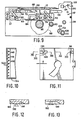
- the magazine is also open at the oppo-. site side 144B except for two narrow wall portions 148 (see also Figure 10) which adjoin the walls at the other two sides 144C and 144D of the magazine and which limit the insertion of the disc holders 38 into the magazine.
- the disc holders are initially inserted into the magazine through the side 144A thereof after removal of the magazine from the platform 126.
- the disc holders 38 are supported in the magazine 144 by horizontal ribs 146 ( Figures 1 , 2 and 10) formed on the inner sides of the two side walls 144c and 144D of the magazine, the ribs on each wall being spaced from one another by a distance sufficient to allow a disc holder to be slid into and out of the magazine between two adjacent ribs on each wall.
- the disc holders 38 which may be made of a synthetic resin, each have a circular central aperture 42 ( Figure 4) in the bottom of the recess 40 in the holder and a slot 44 extending from this aperture to the periphery of the recess 40.
- the aperture 42 has a diameter slightly larger than that of the turntable 20 of the player 10 so that when a disc holder is being lowered by the loading support 32, 34, 36 to deposit the disc carried by the holder on the turntable, as will be described later herein, the turntable can pass through the aperture.
- the slot 44 is provided for the passage of the read head 26 and also to allow the read head to scan the disc during playing.
- each disc holder On one edge of each disc holder is a protruding tail 158 with two portions 160 which project from the main body of The rail in directions substantially transverse to that in which the disc holders are transferred from the magazine 144 to the loading device 12.
- the orientation of the disc holders in the magazine must be such that their tails 158 protrude from the open side 144B of the magazine for cooperation with a member 152 ( Figures 1 and 2) which forms part of the device 16 by which a small displacement is imparted to a disc holder at the beginning of the transference of that holder from the magazine 144 to the loading device 12.
- the member 152 is situated at the transfer level on top of a housing 150 and is slidably guided for movement in reciprocal directions parallel to the direction of transference of the disc holders, the movement being effected by means of a motor-driven cam mechanism (not shown) in the housing 150.
- the member 152 comprises a pair of grippers in the form of resilient fingers 154 having inwardly directed protrusions 156 at their distal ends.
- the member 152 When a disc holder in the magazine has been brought to the transfer level and is to be transferred from the magazine to the loading device 12, the member 152 is moved forward to abut the projecting portions 160 of the tail 158 of the disc holder with the ends of its gripper fingers 154 and then, since there is no resistance to movement of the disc holder towards the loading device, to push the disc holder from the magazine into the gaps between the upper and lower feed rollers 118 and 116 so that these rollers can feed the disc holder onto the loading support 32, 34, 36.
- the disc holder is fed back into the magazine by the feed rollers 116 and 118, and just before the disc holder leaves the feed rollers the projecting portions 160 of the tail 158 of the disc holder contact the ends of the gripper fingers 154 of the member 152 which has been retained in its forward position by the cam mechanism, and the projecting portions 1 60 of the tail 158 then cooperate with the protrusions 156 at the ends of the gripper fingers 154 to deflect the fingers outwardly, and as the fingers subsequently resile the protrusions 156 engage behind the portions 160 of the tail 158.
- the cam mechanism is then brought into operation by a switching means 180 ( Figures 2, 3 and 5) to retract the member 152 and thereby pull the disc holder back into abutment with the wall portions 148 of the megazine.
- the gripper fingers 154 are then in the position shown in broken lines in Figure 2.
- the disc holder can now move no further, so that as the member 152 continues to move back the gripper fingers are deflected outwardly again by the cooperation between the projecting portions 160 of the tail 158 of the disc holder and-the protrusions 156 at the ends of the gripper fingers, and the return movement of the member 152 to its initial rest position (shown in full lines in Figure 2) is completed.
- the switching means 180 ( Figures 2, 3 and 5) is mounted on the base 2 below the shaft 120 carrying the upper feed rollers 118 and comprises a sensor in the form of a vertically disposed plunger 182 which is urged upwardly by a coil spring 194.
- the plunger is mounted on a U-shaped support 188 which is slidable along horizontal guide rods 186 extending transversely of the direction in which the disc holders are transferred from the magazine 144 to the loading device 12.
- the guide rods 186 are supported by two spaced brackets 1 84 fixed on the base 2.
- the plunger 182 is positioned adjacent a vertical plane which is tangential to the peripheries of the lower feed rollers 1 16 at the sides thereof adjacent the magazine 1 44, and the tip of the plunger projects slightly into the path of movement of the disc holders between the magazine and the feed rollers.
- each disc holder 38 In the underside of each disc holder 38 is a groove 198 ( Figures 2, 11, 12 and 13) which forms a guideway for the plunger 182 for actuating the switching means 1 80.
- the groove opens out of the edge of the disc holder which is adjacent the loading device 12 and comprises a first portion which extends from this edge in a direction parallel to the direction of transference of the disc holders from the magazine 1 44 to the loading device, a second portion which expends obliquely of said direction of transference, and a third portion which extends in a direction parallel to the direction of transference and which is aligned with the plunger 182 of the switching means 180.
- the third portion of the groove decreases gradually in depth to form a ramp surface on the underside of the disc holder at the end of the groove.
- a similar ramp surface is formed in a second groove 196 which opens out of the edge of the disc holder adjacent the groove 198 and which extends wholly in a direction parallel to the direction of transference of the disc holders and is aligned with the plunger 182.
- a third groove 200 similar to the groove 19 6 opens out of the opposite edge of the disc holder, i.e., the edge on which the tail 158 is formed.
- the groove 196 extends wholly in the direction of transference of the disc holder, however, the position of the plunger on the guide rods 186 is not affected and the switching means 180 is not actuated. At the end of this transference of the disc holder the plunger rides up the ramp surface in the groove 200 and then leaves this groove to return to the fully raised position. At the beginning of the transference of the disc holder back from the loading device to the magazine, the plunger 182 is depressed by the ramp surface in the groove 200 and again remains in the same position on the guide rods 186. Just before the disc holder leaves the feed rollers 116 and 1 18 however, the plunger rides up the ramp surface in the gears 114.
- the motor 106 also rotates the gearwheels 100, and with them the gearwheels 90, of the gear trains through which the pinions 86 which cooperate with the racks 84 on the drive plate 68 are driven, but at this stage the gearwheels 88 of these gear trains are in their rest position ( Figures 1 and 8), so no rotation is transmitted to the pinions 86, and the drive plates 68, and with them the loading support 32, 34, 36, consequently remain in their rest position.
- the disc holder 38 is now fed in the direction of the arrow A ( Figures 5, 6 and 8) onto the side members 32 and 34 of the loading support by the feed rollers, the disc holder being guided by the guides 46 on the side members 32 and 34. Shortly before the disc holder leaves the feed rollers its leading edge abuts the stops 48 on the side members 32 and 34 so that during the final stage of its movement by the feed' rollers the disc holder imparts a small movement to the loading support in the direction of the arrow A.
- the pins 50 and 52 on the side members of the loading support thus begin to move along the horizontal sections of the guide slots 54 and 56 in the guide plates 28 and 30.
- the disc holder 38 on the loading support leaves the feed rollers 116 and 118 so that it is free to be subsequently moved in the vertical direction.
- the pins 50 and 52 are at the ends of the horizontal sections of the guide slots 54 and 56, as shown in Figure 6, the disc 22 in the disc holder 38 is located with its centre hole 22A directly above the centering pin 24 of the turntable 20 of the player 10. Also, the pins 50 are engaged in the recesses 64 in the cheek plates 60 of the arm 58 carrying the pressure ring 66.
- the motor 106 When the disc 22 has been played the motor 106, under the command of a signal emitted by the read head 26 and fed into the micro-processes, operates in the reverse direction to move the drive plates 68 back to the rest position. During this movement the drive plates, through the cooperation between the inclined slots 78 and 80 and the pins 50 and 52 and the guidance of the pins 50 and 52 in the slots 54 and 56, raise the loading support 32, 34, 36 so that the disc holder 38 lifts the disc 22 off the centering pin 24. Simultaneously, as the pins 50 move up the vertical sections of the guide slots 54, the arm 58 is returned to its inoperative position.
- the loading support is then moved horizontally by the drive plates 68 back to its rest position, and during this movement the disc holder 38 enters the gaps between the upper and lower feed rollers 118 and 116.
- the return of the drive plates to the rest position also brings the racks 84 out of mesh with the pinions 86 and disengages the gearwheels 88 from the gearwheels 90.
- the feed rollers slide the disc holder 38 off the loading support and onto the appropriate pair of ribs 146 in the magazine 144.
- the grippers 154 of the member 152 of the device 16 engage behind the laterally projecting portions 160 of the tail 158 of the disc holder, and at the same time the groove 198 in the underside of the disc holder displaces the plunger 182 of the switching means 1 80 to close the switch 192 and thereby operate the member 152 to pull the disc holder into its fully inserted position in the magazine 144.
- This final movement of the disc holder results in the motor 106 being automatically switched off by the device which initially started the motor.
- the switching means 180 can also be arranged to switch off the motor 106.
- the loading device comprises two assemblies each comprising a guide plate with L-shaped guide slots, a drive plate with inclined slots and with horizontal guide slots, pins for cooperating with these slots, a toothed rack on the drive plate and a pinion for cooperation with the rack, and gearwheels for transmitting drive to the pinion. It is within the scope of the invention to have an arrangement in which the loading device comprises only one such assembly.
Landscapes
- Automatic Disk Changers (AREA)
Applications Claiming Priority (4)
| Application Number | Priority Date | Filing Date | Title |
|---|---|---|---|
| JP20216182A JPS5994272A (ja) | 1982-11-19 | 1982-11-19 | コンパクトデイスクプレ−ヤ用オ−トチエンジヤ |
| JP202161/82 | 1982-11-19 | ||
| JP19523782U JPS5999252U (ja) | 1982-12-24 | 1982-12-24 | コンパクトデイスクプレ−ヤ用プレツシヤア−ム連動機構 |
| JP195237/82U | 1982-12-24 |
Publications (3)
| Publication Number | Publication Date |
|---|---|
| EP0109711A2 true EP0109711A2 (de) | 1984-05-30 |
| EP0109711A3 EP0109711A3 (en) | 1984-07-04 |
| EP0109711B1 EP0109711B1 (de) | 1988-04-06 |
Family
ID=26509003
Family Applications (1)
| Application Number | Title | Priority Date | Filing Date |
|---|---|---|---|
| EP83201623A Expired EP0109711B1 (de) | 1982-11-19 | 1983-11-15 | Gerät für plattenförmige Aufzeichnungsträger |
Country Status (3)
| Country | Link |
|---|---|
| US (1) | US4479210A (de) |
| EP (1) | EP0109711B1 (de) |
| DE (1) | DE3376240D1 (de) |
Cited By (8)
| Publication number | Priority date | Publication date | Assignee | Title |
|---|---|---|---|---|
| EP0158360A2 (de) * | 1984-04-12 | 1985-10-16 | Yamaha Corporation | Plattenwiedergabegerät |
| FR2565392A1 (fr) * | 1984-05-31 | 1985-12-06 | Sony Corp | Lecteur de disques a changement automatique de disques comprenant un element de verrouillage pour verrouiller le chargeur de disques sur le mecanisme, chargeur de disques et lecture de signaux d'information |
| EP0168107A2 (de) * | 1984-07-11 | 1986-01-15 | Koninklijke Philips Electronics N.V. | Magazin für eine Vielzahl von in Behältern aufgenommenen plattenförmigen Informationsträgern und Kombination eines Plattenspielers mit solch einem Magazin |
| EP0212244A1 (de) * | 1985-07-12 | 1987-03-04 | Pioneer Electronic Corporation | Plattengerät |
| EP0308610A1 (de) * | 1987-08-27 | 1989-03-29 | Deutsche Thomson-Brandt GmbH | Vorrichtung zur Entnahme und zum Abspielen eines plattenförmigen Aufzeichnungsträgers aus den Fächern eines Magazins |
| EP0316953A2 (de) * | 1987-11-18 | 1989-05-24 | Sanyo Electric Co., Ltd. | Aufnahme-Wiedergabegerät für magnetische Plattenkassetten mit automatischen Platten-Wechselmechanismus |
| EP0563927A2 (de) * | 1992-03-31 | 1993-10-06 | Sony Corporation | Mit Plattenwechsler versehener Plattenspieler |
| AU2002319296B2 (en) * | 2001-07-23 | 2007-08-30 | Bayer Schering Pharma Aktiengesellschaft | Use of 2-alkoxyphenyl-substituted imidazotriazinones for the treatment of diseases associated with cGMP regulated processes |
Families Citing this family (27)
| Publication number | Priority date | Publication date | Assignee | Title |
|---|---|---|---|---|
| JPS59151366A (ja) * | 1983-01-31 | 1984-08-29 | Toshiba Corp | 磁気デイスク装置 |
| DE3415412A1 (de) * | 1983-04-25 | 1984-12-20 | Canon K.K., Tokio/Tokyo | Aufzeichnungs- oder wiedergabevorrichtung |
| US4545045A (en) * | 1983-05-31 | 1985-10-01 | Storage Technology Partners Ii | Recording disk load and unload apparatus |
| JPS59221884A (ja) * | 1983-05-31 | 1984-12-13 | Toshiba Corp | フロツピ−磁気デイスク装置 |
| JPS6031764U (ja) * | 1983-08-03 | 1985-03-04 | アルプス電気株式会社 | デイスクカ−トリツジ用記録再生装置 |
| EP0137311B1 (de) * | 1983-09-08 | 1988-12-14 | Fuji Photo Film Co., Ltd. | Gerät zum Laden oder Entladen einer Magnetplattenpackung |
| JPS6065279U (ja) * | 1983-10-08 | 1985-05-09 | 日本マランツ株式会社 | コンパクトデイスクプレ−ヤのトレイボツクス |
| JPS6098140U (ja) * | 1983-12-07 | 1985-07-04 | 日本マランツ株式会社 | コンパクトデイスクプレ−ヤのデイスククランプ装置 |
| JPS60147965A (ja) * | 1984-01-10 | 1985-08-05 | Toshiba Corp | フロツピ−デイスク装置 |
| JPH0636267B2 (ja) * | 1984-09-19 | 1994-05-11 | キヤノン株式会社 | 記録又は再生装置 |
| DE3542343A1 (de) * | 1984-12-03 | 1986-06-05 | Olympus Optical Co., Ltd., Tokio/Tokyo | Informationsaufzeichnungs regenerationsvorrichtung |
| KR900002980B1 (en) * | 1985-01-23 | 1990-05-03 | Sanyo Electric Co | Disc player |
| US4646178A (en) * | 1985-02-19 | 1987-02-24 | Mountain Computer Incorporated | Transport for open or closed flap diskettes |
| NL8500593A (nl) * | 1985-03-04 | 1986-10-01 | Philips Nv | Platenspeler met een laadmechanisme voor het laden van een plaat. |
| JP2566924B2 (ja) * | 1986-07-14 | 1996-12-25 | キヤノン株式会社 | 光磁気記録装置 |
| US5247500A (en) * | 1987-12-09 | 1993-09-21 | Matsushita Electric Industrial Co., Ltd. | Elevating and lowering system in a multi-disk player |
| US4928192A (en) * | 1987-12-23 | 1990-05-22 | Konica Corporation | Process for identifying disks and automatically configuring a disk drive system |
| NL8800448A (nl) * | 1988-02-23 | 1989-09-18 | Philips Nv | Laadinrichting, alsmede een platenspeler voorzien van de laadinrichting. |
| GB2238158B (en) * | 1989-10-16 | 1994-02-09 | Alpine Electronics Inc | Disk loading device |
| US5175656A (en) * | 1989-11-07 | 1992-12-29 | Mitsubishi Denki Kabushiki Kaisha | Disk cartridge loadings/unloading system |
| US5025338A (en) * | 1990-04-27 | 1991-06-18 | Car Mate Mfg. Co., Ltd. | Automatic disc carrying and playing device |
| US5247407A (en) * | 1991-03-15 | 1993-09-21 | Rimage Corporation | Disk loading system |
| KR960008038B1 (ko) * | 1993-12-28 | 1996-06-19 | 대우전자 주식회사 | 미니디스크겸용 콤팩트디스크플레이어의 콤팩트디스크클램프장치 |
| US5828647A (en) * | 1995-07-07 | 1998-10-27 | Samsung Electronics Co., Ltd. | Disk changer with reduced driving time |
| JP2001200314A (ja) * | 2000-01-18 | 2001-07-24 | Ntn Corp | 車輪軸受装置 |
| US20060080686A1 (en) * | 2002-10-29 | 2006-04-13 | Koninklijke Philips Electronics, N.V. | Disk drive unit having a loading mechanism |
| TWI412026B (zh) * | 2010-05-06 | 2013-10-11 | Univ Nat Chiao Tung | 感測裝置 |
Citations (5)
| Publication number | Priority date | Publication date | Assignee | Title |
|---|---|---|---|---|
| DE2330818B2 (de) * | 1972-06-21 | 1976-04-22 | International Business Machines Corp., Armonk, N.Y. (V.St.A.) | Vorrichtung zum einspannen und zentrieren von flexiblen folienscheiben |
| GB2039128A (en) * | 1978-12-28 | 1980-07-30 | Clarion Co Ltd | Automatic casette loading in magnetic tape recording/reproducing apparatus |
| DE2921410B2 (de) * | 1978-06-05 | 1981-03-19 | Naamloze Vennootschap Philips' Gloeilampenfabrieken, Eindhoven | Vorrichtung zum Zentrieren, Ausrichten und Festklemmen einer drehenden Platte |
| DE3214274A1 (de) * | 1981-04-17 | 1982-11-11 | Staar S.A., 1080 Bruxelles | Selbsttaetige wendeeinrichtung fuer videoplatten |
| FR2516289A1 (fr) * | 1981-11-09 | 1983-05-13 | Staar Sa | Dispositif d'insertion et d'ejection d'une cassette ou d'un disque pour appareil d'enregistrement et de lecture |
Family Cites Families (3)
| Publication number | Priority date | Publication date | Assignee | Title |
|---|---|---|---|---|
| DE2143382C3 (de) * | 1971-08-26 | 1974-08-08 | Ted Bildplatten Ag Aeg-Telefunkenteldec, Zug (Schweiz) | Verfahren zum Zuführen eines Aufzeichnungsträgers in eine Wiedergabeeinrichtung, sowie Wiedergabeeinrichtung und Schutzhülle, zur Durchführung des Verfahrens |
| JPS5935112B2 (ja) * | 1977-10-19 | 1984-08-27 | 株式会社東芝 | 可撓性デスク駆動装置 |
| JPS55125575A (en) * | 1979-03-20 | 1980-09-27 | Sharp Corp | Record player |
-
1983
- 1983-11-14 US US06/551,223 patent/US4479210A/en not_active Expired - Fee Related
- 1983-11-15 EP EP83201623A patent/EP0109711B1/de not_active Expired
- 1983-11-15 DE DE8383201623T patent/DE3376240D1/de not_active Expired
Patent Citations (7)
| Publication number | Priority date | Publication date | Assignee | Title |
|---|---|---|---|---|
| DE2330818B2 (de) * | 1972-06-21 | 1976-04-22 | International Business Machines Corp., Armonk, N.Y. (V.St.A.) | Vorrichtung zum einspannen und zentrieren von flexiblen folienscheiben |
| DE2921410B2 (de) * | 1978-06-05 | 1981-03-19 | Naamloze Vennootschap Philips' Gloeilampenfabrieken, Eindhoven | Vorrichtung zum Zentrieren, Ausrichten und Festklemmen einer drehenden Platte |
| GB2039128A (en) * | 1978-12-28 | 1980-07-30 | Clarion Co Ltd | Automatic casette loading in magnetic tape recording/reproducing apparatus |
| DE3214274A1 (de) * | 1981-04-17 | 1982-11-11 | Staar S.A., 1080 Bruxelles | Selbsttaetige wendeeinrichtung fuer videoplatten |
| FR2516289A1 (fr) * | 1981-11-09 | 1983-05-13 | Staar Sa | Dispositif d'insertion et d'ejection d'une cassette ou d'un disque pour appareil d'enregistrement et de lecture |
| DE3241361A1 (de) * | 1981-11-09 | 1983-05-19 | Staar S.A., 1080 Bruxelles | Vorrichtung zum einsetzen und auswerfen einer kassette oder schallplatte fuer ein aufzeichnungs- und/oder wiedergabegeraet |
| GB2112994A (en) * | 1981-11-09 | 1983-07-27 | Staar Sa | A device for the insertion and ejection of a cassette or a disc in a recorder and/or player apparatus |
Cited By (14)
| Publication number | Priority date | Publication date | Assignee | Title |
|---|---|---|---|---|
| EP0158360A2 (de) * | 1984-04-12 | 1985-10-16 | Yamaha Corporation | Plattenwiedergabegerät |
| EP0158360A3 (en) * | 1984-04-12 | 1987-09-30 | Nippon Gakki Seizo Kabushiki Kaisha | Disc reproducing apparatus |
| FR2565392A1 (fr) * | 1984-05-31 | 1985-12-06 | Sony Corp | Lecteur de disques a changement automatique de disques comprenant un element de verrouillage pour verrouiller le chargeur de disques sur le mecanisme, chargeur de disques et lecture de signaux d'information |
| EP0168107A2 (de) * | 1984-07-11 | 1986-01-15 | Koninklijke Philips Electronics N.V. | Magazin für eine Vielzahl von in Behältern aufgenommenen plattenförmigen Informationsträgern und Kombination eines Plattenspielers mit solch einem Magazin |
| EP0168107A3 (de) * | 1984-07-11 | 1988-01-13 | Koninklijke Philips Electronics N.V. | Magazin für eine Vielzahl von in Behältern aufgenommenen plattenförmigen Informationsträgern und Kombination eines Plattenspielers mit solch einem Magazin |
| EP0212244A1 (de) * | 1985-07-12 | 1987-03-04 | Pioneer Electronic Corporation | Plattengerät |
| EP0308610A1 (de) * | 1987-08-27 | 1989-03-29 | Deutsche Thomson-Brandt GmbH | Vorrichtung zur Entnahme und zum Abspielen eines plattenförmigen Aufzeichnungsträgers aus den Fächern eines Magazins |
| EP0316953A2 (de) * | 1987-11-18 | 1989-05-24 | Sanyo Electric Co., Ltd. | Aufnahme-Wiedergabegerät für magnetische Plattenkassetten mit automatischen Platten-Wechselmechanismus |
| EP0316953A3 (de) * | 1987-11-18 | 1990-01-10 | Sanyo Electric Co., Ltd. | Aufnahme-Wiedergabegerät für magnetische Plattenkassetten mit automatischen Platten-Wechselmechanismus |
| US5027237A (en) * | 1987-11-18 | 1991-06-25 | Sanyo Electric Co., Ltd. | Recording-reproduction apparatus for magnetic disc packs with an automatic pack changing mechanism |
| EP0563927A2 (de) * | 1992-03-31 | 1993-10-06 | Sony Corporation | Mit Plattenwechsler versehener Plattenspieler |
| EP0563927A3 (de) * | 1992-03-31 | 1994-08-03 | Sony Corp | |
| US5384760A (en) * | 1992-03-31 | 1995-01-24 | Sony Corporation | Disk changer player with stocker between loading/unloading position and reproducing unit |
| AU2002319296B2 (en) * | 2001-07-23 | 2007-08-30 | Bayer Schering Pharma Aktiengesellschaft | Use of 2-alkoxyphenyl-substituted imidazotriazinones for the treatment of diseases associated with cGMP regulated processes |
Also Published As
| Publication number | Publication date |
|---|---|
| EP0109711A3 (en) | 1984-07-04 |
| EP0109711B1 (de) | 1988-04-06 |
| DE3376240D1 (en) | 1988-05-11 |
| US4479210A (en) | 1984-10-23 |
Similar Documents
| Publication | Publication Date | Title |
|---|---|---|
| EP0109711A2 (de) | Gerät für plattenförmige Aufzeichnungsträger | |
| US4481618A (en) | Loading device for a recording and/or playback apparatus | |
| US4561078A (en) | Disc changer and disc holder and box for use with such a changer | |
| KR920008985B1 (ko) | 디스크 교환 장치 | |
| US5317554A (en) | Magazine loader having an ejector arm | |
| US5123001A (en) | Disk playback device | |
| JPS5923029B2 (ja) | ディスク駆動装置 | |
| EP0526204B1 (de) | Plattenspieler zum Abspielen von einer nackten oder in einer Kassette eingeschlossener Platte | |
| US3899181A (en) | Playback method and system | |
| US6256280B1 (en) | Disk ejection device | |
| US3589733A (en) | Apparatus for changing and playing back recorder tape magazines | |
| EP0146179B1 (de) | Plattenspieler | |
| EP0128331A1 (de) | Vorrichtung zum Positionieren und Verriegeln einer mit Informationen versehenen Platte | |
| US3756608A (en) | Automatic cassette changer | |
| US4686665A (en) | Mode switching device in a disc playback device | |
| US5331484A (en) | Magnetic tape cassette apparatus having a control rod, switching transmitters, and a catch rod | |
| JPH0289247A (ja) | 情報記録再生装置 | |
| US5043969A (en) | Two-stage linear drive apparatus for an information storage disk drive system | |
| US5828647A (en) | Disk changer with reduced driving time | |
| KR0147231B1 (ko) | 디스크 자동 교환 장치의 누름장치 | |
| KR100213766B1 (ko) | 멀티 체인저 콤팩트 디스크 플레이어 | |
| US5917786A (en) | Reduced size automatic loading disc changer | |
| EP0315256A1 (de) | Plattenspieler mit einer Ladevorrichtung zum Laden einer Platte | |
| JP2900665B2 (ja) | ディスクローディング装置 | |
| KR0155844B1 (ko) | 디스크 체인저 |
Legal Events
| Date | Code | Title | Description |
|---|---|---|---|
| PUAI | Public reference made under article 153(3) epc to a published international application that has entered the european phase |
Free format text: ORIGINAL CODE: 0009012 |
|
| PUAL | Search report despatched |
Free format text: ORIGINAL CODE: 0009013 |
|
| AK | Designated contracting states |
Designated state(s): DE FR GB |
|
| AK | Designated contracting states |
Designated state(s): DE FR GB |
|
| 17P | Request for examination filed |
Effective date: 19841130 |
|
| R17P | Request for examination filed (corrected) |
Effective date: 19841130 |
|
| 17Q | First examination report despatched |
Effective date: 19860731 |
|
| GRAA | (expected) grant |
Free format text: ORIGINAL CODE: 0009210 |
|
| AK | Designated contracting states |
Kind code of ref document: B1 Designated state(s): DE FR GB |
|
| REF | Corresponds to: |
Ref document number: 3376240 Country of ref document: DE Date of ref document: 19880511 |
|
| ET | Fr: translation filed | ||
| PLBE | No opposition filed within time limit |
Free format text: ORIGINAL CODE: 0009261 |
|
| STAA | Information on the status of an ep patent application or granted ep patent |
Free format text: STATUS: NO OPPOSITION FILED WITHIN TIME LIMIT |
|
| 26N | No opposition filed | ||
| PGFP | Annual fee paid to national office [announced via postgrant information from national office to epo] |
Ref country code: GB Payment date: 19941031 Year of fee payment: 12 |
|
| PGFP | Annual fee paid to national office [announced via postgrant information from national office to epo] |
Ref country code: FR Payment date: 19941125 Year of fee payment: 12 |
|
| PGFP | Annual fee paid to national office [announced via postgrant information from national office to epo] |
Ref country code: DE Payment date: 19950124 Year of fee payment: 12 |
|
| PG25 | Lapsed in a contracting state [announced via postgrant information from national office to epo] |
Ref country code: GB Effective date: 19951115 |
|
| GBPC | Gb: european patent ceased through non-payment of renewal fee |
Effective date: 19951115 |
|
| PG25 | Lapsed in a contracting state [announced via postgrant information from national office to epo] |
Ref country code: FR Effective date: 19960731 |
|
| PG25 | Lapsed in a contracting state [announced via postgrant information from national office to epo] |
Ref country code: DE Effective date: 19960801 |
|
| REG | Reference to a national code |
Ref country code: FR Ref legal event code: ST |