EP0109478A1 - Dispositif à commande de la vitesse d'un véhicule - Google Patents
Dispositif à commande de la vitesse d'un véhicule Download PDFInfo
- Publication number
- EP0109478A1 EP0109478A1 EP83104892A EP83104892A EP0109478A1 EP 0109478 A1 EP0109478 A1 EP 0109478A1 EP 83104892 A EP83104892 A EP 83104892A EP 83104892 A EP83104892 A EP 83104892A EP 0109478 A1 EP0109478 A1 EP 0109478A1
- Authority
- EP
- European Patent Office
- Prior art keywords
- actuator
- input
- signal
- alarm
- comparator
- Prior art date
- Legal status (The legal status is an assumption and is not a legal conclusion. Google has not performed a legal analysis and makes no representation as to the accuracy of the status listed.)
- Granted
Links
- 239000000203 mixture Substances 0.000 claims abstract description 4
- 230000002950 deficient Effects 0.000 description 4
- 238000010586 diagram Methods 0.000 description 4
- 230000007257 malfunction Effects 0.000 description 2
- 238000011144 upstream manufacturing Methods 0.000 description 2
- 230000007423 decrease Effects 0.000 description 1
- 230000007547 defect Effects 0.000 description 1
- 238000006073 displacement reaction Methods 0.000 description 1
- 238000000034 method Methods 0.000 description 1
- 238000012544 monitoring process Methods 0.000 description 1
Images
Classifications
-
- B—PERFORMING OPERATIONS; TRANSPORTING
- B60—VEHICLES IN GENERAL
- B60K—ARRANGEMENT OR MOUNTING OF PROPULSION UNITS OR OF TRANSMISSIONS IN VEHICLES; ARRANGEMENT OR MOUNTING OF PLURAL DIVERSE PRIME-MOVERS IN VEHICLES; AUXILIARY DRIVES FOR VEHICLES; INSTRUMENTATION OR DASHBOARDS FOR VEHICLES; ARRANGEMENTS IN CONNECTION WITH COOLING, AIR INTAKE, GAS EXHAUST OR FUEL SUPPLY OF PROPULSION UNITS IN VEHICLES
- B60K31/00—Vehicle fittings, acting on a single sub-unit only, for automatically controlling vehicle speed, i.e. preventing speed from exceeding an arbitrarily established velocity or maintaining speed at a particular velocity, as selected by the vehicle operator
- B60K31/02—Vehicle fittings, acting on a single sub-unit only, for automatically controlling vehicle speed, i.e. preventing speed from exceeding an arbitrarily established velocity or maintaining speed at a particular velocity, as selected by the vehicle operator including electrically actuated servomechanism including an electric control system or a servomechanism in which the vehicle velocity affecting element is actuated electrically
- B60K31/04—Vehicle fittings, acting on a single sub-unit only, for automatically controlling vehicle speed, i.e. preventing speed from exceeding an arbitrarily established velocity or maintaining speed at a particular velocity, as selected by the vehicle operator including electrically actuated servomechanism including an electric control system or a servomechanism in which the vehicle velocity affecting element is actuated electrically and means for comparing one electrical quantity, e.g. voltage, pulse, waveform, flux, or the like, with another quantity of a like kind, which comparison means is involved in the development of an electrical signal which is fed into the controlling means
- B60K31/042—Vehicle fittings, acting on a single sub-unit only, for automatically controlling vehicle speed, i.e. preventing speed from exceeding an arbitrarily established velocity or maintaining speed at a particular velocity, as selected by the vehicle operator including electrically actuated servomechanism including an electric control system or a servomechanism in which the vehicle velocity affecting element is actuated electrically and means for comparing one electrical quantity, e.g. voltage, pulse, waveform, flux, or the like, with another quantity of a like kind, which comparison means is involved in the development of an electrical signal which is fed into the controlling means where at least one electrical quantity is set by the vehicle operator
- B60K31/045—Vehicle fittings, acting on a single sub-unit only, for automatically controlling vehicle speed, i.e. preventing speed from exceeding an arbitrarily established velocity or maintaining speed at a particular velocity, as selected by the vehicle operator including electrically actuated servomechanism including an electric control system or a servomechanism in which the vehicle velocity affecting element is actuated electrically and means for comparing one electrical quantity, e.g. voltage, pulse, waveform, flux, or the like, with another quantity of a like kind, which comparison means is involved in the development of an electrical signal which is fed into the controlling means where at least one electrical quantity is set by the vehicle operator in a memory, e.g. a capacitor
- B60K31/047—Vehicle fittings, acting on a single sub-unit only, for automatically controlling vehicle speed, i.e. preventing speed from exceeding an arbitrarily established velocity or maintaining speed at a particular velocity, as selected by the vehicle operator including electrically actuated servomechanism including an electric control system or a servomechanism in which the vehicle velocity affecting element is actuated electrically and means for comparing one electrical quantity, e.g. voltage, pulse, waveform, flux, or the like, with another quantity of a like kind, which comparison means is involved in the development of an electrical signal which is fed into the controlling means where at least one electrical quantity is set by the vehicle operator in a memory, e.g. a capacitor the memory being digital
-
- B—PERFORMING OPERATIONS; TRANSPORTING
- B60—VEHICLES IN GENERAL
- B60W—CONJOINT CONTROL OF VEHICLE SUB-UNITS OF DIFFERENT TYPE OR DIFFERENT FUNCTION; CONTROL SYSTEMS SPECIALLY ADAPTED FOR HYBRID VEHICLES; ROAD VEHICLE DRIVE CONTROL SYSTEMS FOR PURPOSES NOT RELATED TO THE CONTROL OF A PARTICULAR SUB-UNIT
- B60W30/00—Purposes of road vehicle drive control systems not related to the control of a particular sub-unit, e.g. of systems using conjoint control of vehicle sub-units
- B60W30/18—Propelling the vehicle
- B60W30/18009—Propelling the vehicle related to particular drive situations
- B60W30/18027—Drive off, accelerating from standstill
-
- B—PERFORMING OPERATIONS; TRANSPORTING
- B60—VEHICLES IN GENERAL
- B60W—CONJOINT CONTROL OF VEHICLE SUB-UNITS OF DIFFERENT TYPE OR DIFFERENT FUNCTION; CONTROL SYSTEMS SPECIALLY ADAPTED FOR HYBRID VEHICLES; ROAD VEHICLE DRIVE CONTROL SYSTEMS FOR PURPOSES NOT RELATED TO THE CONTROL OF A PARTICULAR SUB-UNIT
- B60W50/00—Details of control systems for road vehicle drive control not related to the control of a particular sub-unit, e.g. process diagnostic or vehicle driver interfaces
- B60W2050/0001—Details of the control system
- B60W2050/0019—Control system elements or transfer functions
- B60W2050/0028—Mathematical models, e.g. for simulation
- B60W2050/0031—Mathematical model of the vehicle
-
- B—PERFORMING OPERATIONS; TRANSPORTING
- B60—VEHICLES IN GENERAL
- B60W—CONJOINT CONTROL OF VEHICLE SUB-UNITS OF DIFFERENT TYPE OR DIFFERENT FUNCTION; CONTROL SYSTEMS SPECIALLY ADAPTED FOR HYBRID VEHICLES; ROAD VEHICLE DRIVE CONTROL SYSTEMS FOR PURPOSES NOT RELATED TO THE CONTROL OF A PARTICULAR SUB-UNIT
- B60W2530/00—Input parameters relating to vehicle conditions or values, not covered by groups B60W2510/00 or B60W2520/00
- B60W2530/16—Driving resistance
-
- B—PERFORMING OPERATIONS; TRANSPORTING
- B60—VEHICLES IN GENERAL
- B60W—CONJOINT CONTROL OF VEHICLE SUB-UNITS OF DIFFERENT TYPE OR DIFFERENT FUNCTION; CONTROL SYSTEMS SPECIALLY ADAPTED FOR HYBRID VEHICLES; ROAD VEHICLE DRIVE CONTROL SYSTEMS FOR PURPOSES NOT RELATED TO THE CONTROL OF A PARTICULAR SUB-UNIT
- B60W2720/00—Output or target parameters relating to overall vehicle dynamics
- B60W2720/10—Longitudinal speed
- B60W2720/106—Longitudinal acceleration
Definitions
- the invention relates to a device for controlling the driving speed of a motor vehicle with a setpoint generator adjustable by an accelerator pedal, the output signal of which can be applied to an actuator of an element influencing the fuel-air mixture, with an actuator generator that generates a signal corresponding to the position of the actuator, and with an alarm circuit via which an alarm signal can be fed to an alarm device if the actuator is in a gas position when the setpoint transmitter is not actuated.
- a pedal contact that can be actuated by the accelerator pedal and an actuator contact that can be actuated by the actuator are connected in parallel in the alarm circuit.
- the pedal contact is open in the idle position of the accelerator pedal and the actuator contact is closed in the idle position of the actuator. Since the switching point of the Pe dalkontact with a lower deflection of the accelerator pedal from the idle position than the switching point of the actuator contact with corresponding deflection of the actuator from the idle position, current flow through the alarm circuit is always possible with an intact control device, which means that no alarm signal is given. However, if the actuator is not in its idle position even though the accelerator pedal is not actuated, the pedal contact and the actuator contact are open and the current flow in the alarm circuit is thus interrupted. This means that an alarm signal is supplied to the alarm device.
- a first branch of the alarm circuit emits an alarm signal at its output when the setpoint generator generates an idle signal when the accelerator pedal is actuated
- a second branch of the alarm circuit emits an alarm signal at its output when the actuator is actuated Actuator generates an idle signal.
- the alarm signal of the first branch before the alarm signal of the second branch of the alarm circuit can be issued.
- the first branch of the alarm circuit can have a comparator, at whose first input there is a constant electrical signal which corresponds to a specific deflection position of the setpoint generator from the idle position, and at whose second input there is an electrical signal corresponding to the respective position of the setpoint generator, the output the comparator is fed to a first input of an AND gate, at the second input of which a signal can be applied when the accelerator pedal is deflected from the idle position, and according to which the second branch of the alarm circuit has a second comparator, at the first input of which there is a constant electrical signal which corresponds to a specific deflection position of the actuator from the idle position and an electrical signal corresponding to the respective position of the actuator is present at its second input, the output of the second comparator being fed to a first input of a second AND element conducts, at whose second input a signal can be applied when the actuator is deflected from the idle position and that both the output of the first and of the second AND element is connected to the alarm device.
- the second comparator works in the same way in that the first input of the second comparator is the positive input and a signal which decreases in size is present when the actuator is displaced from its idle position when the actuator is displaced from its idle position.
- the input signals of the comparators are generated with simple means if the first input of the first and / or second comparator is connected to a voltage divider and if the second input of the first and / or second comparator is connected to a potentiometer forming the setpoint generator or the actuator transmitter .
- the function of the accelerator pedal is preferably monitored by arranging the second input of the first AND gate with a pedal contact which can be actuated by the accelerator pedal in the idle position of the accelerator pedal and which is closed when the accelerator pedal is actuated, while in the same way monitoring the function of the actuator takes place that the second input of the second AND element is arranged an actuator contact which can be actuated by the actuator in the idle position of the actuator and which is actuated when the actuator is actuated gate is open and when the first input of the AND gate is inverted.
- the input of the AND gate coming from the comparator receives a positive signal until the size of the setpoint signal reaches the constant signal size at the positive comparator input Has. During this time there is still no positive signal due to the open pedal contact at the second input of the AND gate. However, the comparator's positive signal is deleted. Only when the accelerator pedal is deflected further does the pedal switch close and the second input of the AND gate receives a positive signal. However, since there is no longer a positive signal at the first input, the AND gate cannot give an alarm signal to the alarm device.
- the second comparator works according to the same principle, in which the switching point is greater deflection of the actuator than the switching point of the actuator contact. This means that the comparator feeds a positive signal to the second AND gate until the size of the actuator signal reaches the size of the constant signal at the positive input of the comparator. So stale the comparator reverses and feeds a negative signal to the AND gate. Since this signal is inverted at the AND gate, the previously negative signal changes to a positive signal. With further adjustment of the actuator, the previously closed actuator contact opens and the second input of the AND element receives a negative signal instead of a positive one. In the event of a defect in the actuator or the actuator contact, the same signals are present at the inputs of the AND element, so that the latter emits an alarm signal.
- the switching point of the actuator contact is greater deflection of the actuator than the switching point of the pedal contact with a corresponding deflection of the accelerator pedal.
- the alarm device can be a lamp.
- the alarm device can be preceded by a timing element, which is preferably an RC element.
- a permanent and not only brief exposure to the alarm device is achieved if the alarm device has a memory element, e.g. a flip-flop is connected upstream.
- a memory element e.g. a flip-flop is connected upstream.
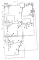
- the device shown in FIG. 1 has a setpoint generator 2 which is adjustable by a gas pedal 1 and is designed as a potentiometer. Its output signal is fed to an electrical controller 3, which controls an actuator drive 4 via an amplifier 9.
- An actuator 5 formed by a throttle valve for influencing the fuel-air mixture and an actuator transmitter 29 formed by a potentiometer can be adjusted.
- the faultless function of the device for controlling the driving speed can be monitored by an alarm circuit consisting of a first branch 6 and a second branch 7, of which an alarm device formed by a lamp 8 can be controlled.
- the first branch 6 of the alarm circuit has a comparator 10, to the first positive input 11 of which a voltage divider 12 is connected.
- This voltage divider 12 applies a constant electrical signal to the input 11, which corresponds to a specific deflection position of the setpoint generator 2 from the idle position of, for example, 8 c .
- the negative second input 13 of the comparator 10 is acted upon by the output signal of the setpoint generator 2, u.z. such that the size of the signal increases with increasing deflection of the setpoint generator 2. If this signal reaches the size of the constant signal present at the input 11, the comparator 10, which had previously emitted a positive signal, now outputs a negative output signal to a first input 15 of an AND gate 14.
- a pedal contact 18 is arranged in the control line 17 of the second input 16 of the AND gate 14, which can be actuated by the accelerator pedal 1 and is open in the idle position of the accelerator pedal with a somewhat greater deflection of approximately 10 ° of the accelerator pedal 1 from the idle position than that by the voltage divider 12 fixed deflection position is closed.
- the second branch 7 of the alarm circuit has a comparator 20, to the first positive input 21 of which a voltage divider 22 is connected.
- the voltage divider applies a constant electrical signal to this input 21, which corresponds to a specific deflection position of approximately 14 ° of the actuator 29 from the idle position.
- the negative second input 23 of the comparator 20 is acted upon by the output signal of the actuator 29, in such a way that the size of the signal increases with increasing displacement of the actuator 29. If this signal reaches the size of the constant signal present at the input 21, the comparator 20, which until then has given a positive signal, now outputs a negative output signal from a first input 25 of an AND gate 24. Since this first input 25 is inverted, the signal which is detected by the AND gate 24 and which is output negatively by the comparator is positive.
- an actuator contact 28 is arranged, which can be actuated by the actuator 5 and closed in the idle position of the actuator with a somewhat smaller deflection of about 12 ° of the actuator 5 from the idle position than that by the voltage divider 22 fixed deflection position is open.
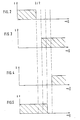
- FIG. 4 shows the signal detected by the AND gate 24 at the inverted input 25 and in FIG. 5 the signal detected at the input 26. From this it can be seen that if the second branch 7 is intact, no alarm signal can be emitted at the output of the AND gate 24.
- the AND element 24 detects two identical signals and thus emits an output signal. Here, too, a false alarm signal is suppressed when switching over by the RC element 19.
- FIGS. 2-5 it can also be seen that the switching point of the actuator contact 28 is greater deflection of the actuator 5 than the switching point of the pedal contact 18 with a corresponding deflection of the accelerator pedal 1. In this way, the two branches 6 and 7 are mutually influenced avoided.
- a storage element 30 configured as a flip-flop upstream of the lamp 8 ensures that the supply line an alarm signal that permanently controls the lamp 8 and thus not only causes it to light up briefly.
- a generated alarm signal is also fed via a line 31 to the controller 3, which is controlled by this alarm signal in such a way that it controls the actuator 4 primarily in a load-reducing manner. A full throttle position of the actuator 5 is thus prevented, but driving at low speed to reach a workshop is made possible.
Landscapes
- Engineering & Computer Science (AREA)
- Transportation (AREA)
- Mechanical Engineering (AREA)
- Chemical & Material Sciences (AREA)
- Combustion & Propulsion (AREA)
- Automation & Control Theory (AREA)
- Auxiliary Drives, Propulsion Controls, And Safety Devices (AREA)
- Control Of Throttle Valves Provided In The Intake System Or In The Exhaust System (AREA)
- Electrical Control Of Air Or Fuel Supplied To Internal-Combustion Engine (AREA)
- Emergency Alarm Devices (AREA)
Applications Claiming Priority (2)
| Application Number | Priority Date | Filing Date | Title |
|---|---|---|---|
| DE3237535 | 1982-10-09 | ||
| DE19823237535 DE3237535A1 (de) | 1982-10-09 | 1982-10-09 | Einrichtung zum steuern der fahrgeschwindigkeit eines kraftfahrzeuges |
Publications (2)
| Publication Number | Publication Date |
|---|---|
| EP0109478A1 true EP0109478A1 (fr) | 1984-05-30 |
| EP0109478B1 EP0109478B1 (fr) | 1986-02-05 |
Family
ID=6175377
Family Applications (1)
| Application Number | Title | Priority Date | Filing Date |
|---|---|---|---|
| EP83104892A Expired EP0109478B1 (fr) | 1982-10-09 | 1983-05-18 | Dispositif à commande de la vitesse d'un véhicule |
Country Status (3)
| Country | Link |
|---|---|
| US (1) | US4488527A (fr) |
| EP (1) | EP0109478B1 (fr) |
| DE (2) | DE3237535A1 (fr) |
Cited By (3)
| Publication number | Priority date | Publication date | Assignee | Title |
|---|---|---|---|---|
| DE3510173A1 (de) * | 1984-08-16 | 1986-02-27 | Robert Bosch Gmbh, 7000 Stuttgart | Ueberwachungseinrichtung fuer eine elektronisch gesteuerte drosselklappe in einem kraftfahrzeug |
| AU608414B2 (en) * | 1988-02-22 | 1991-03-28 | Fujitsu Ten Ltd. | Fail-safe circuit for constant speed drive apparatus |
| DE4216963A1 (de) * | 1992-05-22 | 1993-11-25 | Bosch Gmbh Robert | Steuereinrichtung für eine Verstelleinrichtung in einem Fahrzeug |
Families Citing this family (23)
| Publication number | Priority date | Publication date | Assignee | Title |
|---|---|---|---|---|
| JPS60190626A (ja) * | 1984-03-09 | 1985-09-28 | Hitachi Ltd | 絞弁制御装置 |
| JPH0639922B2 (ja) * | 1985-03-26 | 1994-05-25 | 日産自動車株式会社 | 車両用スロツトル制御装置 |
| JPS61279743A (ja) * | 1985-06-04 | 1986-12-10 | Nissan Motor Co Ltd | 車両用アクセル制御装置 |
| GB8522274D0 (en) * | 1985-09-07 | 1985-10-16 | Romatic Ltd | Speed control unit |
| US4640248A (en) * | 1985-12-23 | 1987-02-03 | General Motors Corporation | Failsafe drive-by-wire engine controller |
| US4854283A (en) * | 1986-11-28 | 1989-08-08 | Nippondenso Co., Ltd. | Throttle valve control apparatus |
| DE3643946A1 (de) * | 1986-12-22 | 1988-06-23 | Vdo Schindling | Elektrischer sollwertgeber |
| US4890231A (en) * | 1987-03-06 | 1989-12-26 | Chrysler Motors Corporation | Method of disabling a resume switch in an electronic speed control system for vehicles |
| US4849892A (en) * | 1987-03-06 | 1989-07-18 | Chrysler Motors Corporation | Method of determining and using an acceleration correction in an integrated acceleration based electronic speed control system for vehicles |
| US4860210A (en) * | 1987-03-06 | 1989-08-22 | Chrysler Motors Corporation | Method of determining and using a filtered speed error in an integrated acceleration based electronic speed control system for vehicles |
| US4896267A (en) * | 1987-03-06 | 1990-01-23 | Chrysler Motors Corporation | Electronic speed control system for vehicles, a method of determining the condition of a manual transmission clutch and of a park/neutral gear in an automatic transmission |
| JPH0196449A (ja) * | 1987-10-06 | 1989-04-14 | Fuji Heavy Ind Ltd | 内燃機関のバルブ制御装置 |
| US4905154A (en) * | 1988-03-14 | 1990-02-27 | Chrysler Motors Corporation | Method for compensating for cable length in a vehicle electronic speed control system |
| JPH0749779B2 (ja) * | 1988-06-14 | 1995-05-31 | 三菱電機株式会社 | スロットルアクチュエータの制御装置 |
| US4881502A (en) * | 1988-08-24 | 1989-11-21 | General Motors Corporation | Pedal force responsive engine controller |
| EP0401224B2 (fr) * | 1988-12-15 | 1994-11-17 | Robert Bosch Gmbh | Systeme de commande pour le moteur a combustion interne d'un vehicule automobile |
| WO1991004400A1 (fr) * | 1989-09-21 | 1991-04-04 | Robert Bosch Gmbh | Systeme de controle pour transducteur de la course utile de la pedale d'acceleration d'un vehicule |
| US5117791A (en) * | 1989-12-15 | 1992-06-02 | Eaton Corporation | Throttle actuator safety method for automated transmission |
| US5048481A (en) * | 1989-12-15 | 1991-09-17 | Eaton Corporation | Throttle actuator safety method for automated transmission |
| JPH086626B2 (ja) * | 1990-05-09 | 1996-01-29 | 本田技研工業株式会社 | 吸気絞り弁制御装置のフェイルセーフ装置 |
| EP0540218A3 (en) * | 1991-11-01 | 1993-06-30 | Lucas Industries Public Limited Company | A method of and an apparatus for detecting a fault in a return system |
| US9056617B2 (en) * | 2011-12-02 | 2015-06-16 | Ford Global Technologies, Llc | Systems and methods for detecting accelerator pedal failure |
| CN112078514B (zh) * | 2020-08-05 | 2022-03-25 | 东风电驱动系统有限公司 | Tft屏报警灯自检方法及装置 |
Citations (5)
| Publication number | Priority date | Publication date | Assignee | Title |
|---|---|---|---|---|
| DE2754813A1 (de) * | 1977-12-09 | 1979-06-13 | Vdo Schindling | Einrichtung zum ueberwachen der betriebsparameter von kraftfahrzeugen |
| FR2411098A1 (fr) * | 1977-12-07 | 1979-07-06 | Vdo Schindling | Appareil automatique de regulation de la vitesse de marche d'un vehicule automobile |
| FR2435369A1 (fr) * | 1978-09-11 | 1980-04-04 | Vdo Schindling | Appareil destine a transmettre la position d'un element de commande actionne par le conducteur d'un vehicule automobile et regulant la vitesse de marche de celui-ci |
| GB2075222A (en) * | 1980-05-05 | 1981-11-11 | Gen Signal Corp | Measuring tachometer output in an automatic speed control system |
| EP0060326A2 (fr) * | 1981-03-13 | 1982-09-22 | VDO Adolf Schindling AG | Installation de sécurité et de surveillance pour dispositifs de commande dans des véhicules |
Family Cites Families (6)
| Publication number | Priority date | Publication date | Assignee | Title |
|---|---|---|---|---|
| US3828742A (en) * | 1972-04-26 | 1974-08-13 | Caterpillar Tractor Co | Engine control system |
| DE2546076C2 (de) * | 1975-10-15 | 1982-07-15 | Volkswagenwerk Ag, 3180 Wolfsburg | Regelanordnung für Verbrennungsmotoren mit einer über einen Einschalter einschaltbaren Drehzahl-Regeleinrichtung |
| DE2754826A1 (de) * | 1977-12-09 | 1979-06-13 | Vdo Schindling | Einrichtung zum regeln der fahrgeschwindigkeit eines kraftfahrzeugs |
| DE2732905C3 (de) * | 1977-07-21 | 1994-02-24 | Vdo Schindling | Einrichtung zum Regeln der Fahrgeschwindigkeit eines Kraftfahrzeugs |
| US4314237A (en) * | 1980-05-27 | 1982-02-02 | American Standard Inc. | Fail-safe acknowledging circuit |
| JPS5828575A (ja) * | 1981-07-23 | 1983-02-19 | Toyota Motor Corp | エンジン自動停止始動装置 |
-
1982
- 1982-10-09 DE DE19823237535 patent/DE3237535A1/de not_active Withdrawn
-
1983
- 1983-05-18 DE DE8383104892T patent/DE3362070D1/de not_active Expired
- 1983-05-18 EP EP83104892A patent/EP0109478B1/fr not_active Expired
- 1983-09-12 US US06/531,125 patent/US4488527A/en not_active Expired - Lifetime
Patent Citations (5)
| Publication number | Priority date | Publication date | Assignee | Title |
|---|---|---|---|---|
| FR2411098A1 (fr) * | 1977-12-07 | 1979-07-06 | Vdo Schindling | Appareil automatique de regulation de la vitesse de marche d'un vehicule automobile |
| DE2754813A1 (de) * | 1977-12-09 | 1979-06-13 | Vdo Schindling | Einrichtung zum ueberwachen der betriebsparameter von kraftfahrzeugen |
| FR2435369A1 (fr) * | 1978-09-11 | 1980-04-04 | Vdo Schindling | Appareil destine a transmettre la position d'un element de commande actionne par le conducteur d'un vehicule automobile et regulant la vitesse de marche de celui-ci |
| GB2075222A (en) * | 1980-05-05 | 1981-11-11 | Gen Signal Corp | Measuring tachometer output in an automatic speed control system |
| EP0060326A2 (fr) * | 1981-03-13 | 1982-09-22 | VDO Adolf Schindling AG | Installation de sécurité et de surveillance pour dispositifs de commande dans des véhicules |
Cited By (3)
| Publication number | Priority date | Publication date | Assignee | Title |
|---|---|---|---|---|
| DE3510173A1 (de) * | 1984-08-16 | 1986-02-27 | Robert Bosch Gmbh, 7000 Stuttgart | Ueberwachungseinrichtung fuer eine elektronisch gesteuerte drosselklappe in einem kraftfahrzeug |
| AU608414B2 (en) * | 1988-02-22 | 1991-03-28 | Fujitsu Ten Ltd. | Fail-safe circuit for constant speed drive apparatus |
| DE4216963A1 (de) * | 1992-05-22 | 1993-11-25 | Bosch Gmbh Robert | Steuereinrichtung für eine Verstelleinrichtung in einem Fahrzeug |
Also Published As
| Publication number | Publication date |
|---|---|
| EP0109478B1 (fr) | 1986-02-05 |
| US4488527A (en) | 1984-12-18 |
| DE3237535A1 (de) | 1984-04-12 |
| DE3362070D1 (en) | 1986-03-20 |
Similar Documents
| Publication | Publication Date | Title |
|---|---|---|
| EP0109478B1 (fr) | Dispositif à commande de la vitesse d'un véhicule | |
| DE2251167C3 (de) | Einrichtung zur Abgasentgiftung von Brennkraftmaschinen | |
| DE2245029C3 (de) | Verfahren und Vorrichtung zur Abgasentgiftung von Brennkraftmaschinen | |
| DE2816257C2 (de) | Regelvorrichtung für das Luft/Brennstoff-Verhältnis von Brennkraftmaschinen mit Luftdurchsatzmessung | |
| EP0468007B1 (fr) | Systeme de commande et/ou de regulation d'un moteur a combustion interne | |
| DE2635308A1 (de) | Vorrichtung zum regeln des einer brennkraftmaschine gelieferten kraftstoff-luftgemisches | |
| DE2206276A1 (de) | Verfahren und vorrichtung zur verminderung von schaedlichen anteilen der abgasemission von brennkraftmaschinen | |
| DE2616693A1 (de) | Zuendanlage, insbesondere fuer brennkraftmaschinen | |
| DE3038354C2 (de) | Elektrische Kraftstoffeinspritz-Steuereinrichtung für eine Brennkraftmaschine | |
| DE3101476A1 (de) | "vorrichtung und verfahren zur automatischen geschwindigkeitseinstellung bei kraftfahrzeugen" | |
| DE3327376C2 (de) | Verfahren und Vorrichtung zur Steuerung der Stellung einer Drosselklappe in Ansaugrohr einer Brennkraftmaschine | |
| EP0131146B1 (fr) | Appareil de commutation électronique, fonctionnant de préférence sans contact | |
| DE3507130A1 (de) | Treiberstromkreis fuer eine magnetspule | |
| EP0123731A1 (fr) | Dispositif pour transmettre la position d'un élément de commande | |
| DE3905479A1 (de) | Stoersicherheitsschaltung fuer einen konstantgeschwindigkeitssteuerapparat | |
| DE2755338C2 (de) | Elektrische Stellvorrichtung für Geschwindigkeitsregeleinrichtungen | |
| DE2700768C2 (de) | Schwellenzündschaltung für ein elektronisches Zündsystem einer Brennkraftmaschine | |
| DE4443224C2 (de) | Brennstoff-Regelsystem mit geschlossenem Regelkreis | |
| EP0134466B1 (fr) | Procédé et dispositif de réglage du lambda du mélange combustible d'un moteur à combustion | |
| DE4322472B4 (de) | Schaltungsanordnung zur Überwachung eines Stellungsgebers | |
| EP0309753A1 (fr) | Procédé de surveillance de charge inductive | |
| DE3921329A1 (de) | Verfahren und vorrichtung zur feststellung einer fehlfunktion einer einen stromregelkreis aufweisenden endstufe in einer leerlaufdrehzahlregelungsanordnung einer brennkraftmaschine | |
| DE2424896A1 (de) | Zuendeinrichtung fuer eine brennkraftmaschine | |
| DE3732079C2 (fr) | ||
| DE3004199C2 (de) | Vorrichtung zum Absperren der Brennstoffzufuhr im Schiebebetrieb eines Verbrennungsmotors |
Legal Events
| Date | Code | Title | Description |
|---|---|---|---|
| PUAI | Public reference made under article 153(3) epc to a published international application that has entered the european phase |
Free format text: ORIGINAL CODE: 0009012 |
|
| AK | Designated contracting states |
Designated state(s): DE FR GB IT SE |
|
| 17P | Request for examination filed |
Effective date: 19840419 |
|
| ITF | It: translation for a ep patent filed |
Owner name: STUDIO JAUMANN |
|
| GRAA | (expected) grant |
Free format text: ORIGINAL CODE: 0009210 |
|
| AK | Designated contracting states |
Designated state(s): DE FR GB IT SE |
|
| ET | Fr: translation filed | ||
| REF | Corresponds to: |
Ref document number: 3362070 Country of ref document: DE Date of ref document: 19860320 |
|
| PLBI | Opposition filed |
Free format text: ORIGINAL CODE: 0009260 |
|
| 26 | Opposition filed |
Opponent name: ROBERT BOSCH GMBH Effective date: 19861104 |
|
| PLBN | Opposition rejected |
Free format text: ORIGINAL CODE: 0009273 |
|
| STAA | Information on the status of an ep patent application or granted ep patent |
Free format text: STATUS: OPPOSITION REJECTED |
|
| 27O | Opposition rejected |
Effective date: 19901126 |
|
| ITTA | It: last paid annual fee | ||
| PGFP | Annual fee paid to national office [announced via postgrant information from national office to epo] |
Ref country code: SE Payment date: 19920410 Year of fee payment: 10 |
|
| PGFP | Annual fee paid to national office [announced via postgrant information from national office to epo] |
Ref country code: FR Payment date: 19920429 Year of fee payment: 10 |
|
| PGFP | Annual fee paid to national office [announced via postgrant information from national office to epo] |
Ref country code: GB Payment date: 19920508 Year of fee payment: 10 |
|
| PG25 | Lapsed in a contracting state [announced via postgrant information from national office to epo] |
Ref country code: GB Effective date: 19930518 |
|
| PG25 | Lapsed in a contracting state [announced via postgrant information from national office to epo] |
Ref country code: SE Effective date: 19930519 |
|
| GBPC | Gb: european patent ceased through non-payment of renewal fee |
Effective date: 19930518 |
|
| PG25 | Lapsed in a contracting state [announced via postgrant information from national office to epo] |
Ref country code: FR Effective date: 19940131 |
|
| REG | Reference to a national code |
Ref country code: FR Ref legal event code: ST |
|
| EUG | Se: european patent has lapsed |
Ref document number: 83104892.1 Effective date: 19931210 |
|
| PGFP | Annual fee paid to national office [announced via postgrant information from national office to epo] |
Ref country code: DE Payment date: 19990414 Year of fee payment: 17 |
|
| PG25 | Lapsed in a contracting state [announced via postgrant information from national office to epo] |
Ref country code: DE Free format text: LAPSE BECAUSE OF NON-PAYMENT OF DUE FEES Effective date: 20010301 |
|
| APAH | Appeal reference modified |
Free format text: ORIGINAL CODE: EPIDOSCREFNO |