EP0108922A1 - Axialgebläse für luftgekühlte Brennkraftmaschine - Google Patents
Axialgebläse für luftgekühlte Brennkraftmaschine Download PDFInfo
- Publication number
- EP0108922A1 EP0108922A1 EP83110032A EP83110032A EP0108922A1 EP 0108922 A1 EP0108922 A1 EP 0108922A1 EP 83110032 A EP83110032 A EP 83110032A EP 83110032 A EP83110032 A EP 83110032A EP 0108922 A1 EP0108922 A1 EP 0108922A1
- Authority
- EP
- European Patent Office
- Prior art keywords
- air
- combustion engine
- blower
- internal combustion
- casing
- Prior art date
- Legal status (The legal status is an assumption and is not a legal conclusion. Google has not performed a legal analysis and makes no representation as to the accuracy of the status listed.)
- Granted
Links
- 238000002485 combustion reaction Methods 0.000 title claims abstract description 14
- 238000001816 cooling Methods 0.000 claims abstract description 13
- 238000011144 upstream manufacturing Methods 0.000 abstract 1
- 230000002411 adverse Effects 0.000 description 3
- 230000004323 axial length Effects 0.000 description 3
- 230000000694 effects Effects 0.000 description 2
- 238000009434 installation Methods 0.000 description 2
- 238000004519 manufacturing process Methods 0.000 description 2
- 241000886569 Cyprogenia stegaria Species 0.000 description 1
- 239000000853 adhesive Substances 0.000 description 1
- 230000001070 adhesive effect Effects 0.000 description 1
- 230000018109 developmental process Effects 0.000 description 1
- 230000001771 impaired effect Effects 0.000 description 1
- 238000007373 indentation Methods 0.000 description 1
Images

Classifications
-
- F—MECHANICAL ENGINEERING; LIGHTING; HEATING; WEAPONS; BLASTING
- F04—POSITIVE - DISPLACEMENT MACHINES FOR LIQUIDS; PUMPS FOR LIQUIDS OR ELASTIC FLUIDS
- F04D—NON-POSITIVE-DISPLACEMENT PUMPS
- F04D29/00—Details, component parts, or accessories
- F04D29/40—Casings; Connections of working fluid
- F04D29/52—Casings; Connections of working fluid for axial pumps
- F04D29/54—Fluid-guiding means, e.g. diffusers
- F04D29/541—Specially adapted for elastic fluid pumps
- F04D29/542—Bladed diffusers
Definitions
- the invention relates to a device of the type specified in the preamble of the first claim.
- the object of the present invention is now to reduce the scope of the blower jacket in axial fans for cooling air delivery on air-cooled internal combustion engines, without the performance and the amount of cooling air delivered by the fan being impaired.
- this object is achieved by the characterizing features of the first claim.
- This solution has the advantage that the flow of the intake cooling air is not adversely affected and that the inlet area is nevertheless not larger than the blower jacket diameter in the area of the impeller. This reduces the installation volume of the cooling air blower, so that the installation dimensions of the associated internal combustion engine can also be reduced.
- the constriction of the blower jacket is advantageously achieved by a circumferential radial constriction. This is easy to manufacture technically (claim 2).
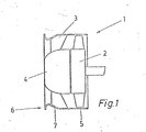
- the figures schematically show a cross section through an axial fan 1, consisting of an impeller 2, a guide impeller 3, the hub 4 and a housing jacket 5.
- the impeller 2 is mounted in a manner known per se with the aid of a V-belt driven by the crankshaft or an intermediate shaft of the internal combustion engine, not shown.
- the guide wheel 3 is shrunk with the hub 4 into the housing shell 5.
- the housing shell 5 is no longer in the inlet area 6 - as was previously usual -. Protrudes due to the inlet radius on the contour of the fan shell section in the region of the impeller 2, the inlet radius 6 shown in Figure 1 is retracted so that the leading edge of the fan casing contour g facilitated with its section in the impeller area. This measure creates a diagonal flow in front of or in the area of the stator 3.
- the impeller 2 itself is flowed through axially. Because of this training, the flow conditions are additionally improved.
- the outlet area 7 of the inlet radius 6, which is at the rear in the direction of flow, is designed to extend into the region of the guide wheel 3 in the case of axially small-sized fans.
- the guide vane 3 is fastened in the blower jacket 5 by shrinking, it is difficult to provide the outlet area 7 as far as into the guide vane area 3, since then reduced adhesive forces can occur during and after the shrinking. In this case, it is then better to move the inlet radius 6 axially forward with an outlet area 7 to such an extent that there is no longer any deformation of the blower jacket 5 in the stator area 3.
- FIG. 2 and 3 differs from that of FIG. 1 in that an insert 8 is provided instead of the constriction.
- the blower jacket 5 has both in the inlet area and in the area of the Impeller 2 has a constant outer circumference.
- the rear region 7 of the insert 8 in the direction of flow in the case of axially small fans is designed to extend into the region of the guide wheel 3.
- the guide vane 3 is fastened in the blower casing 5 by shrinking, it makes sense to provide the insert 8 as far as into the guide vane region 3 and to manufacture both in one piece.
- the insert 8 Due to the front likewise rounded edge 9 of the insert 8 and its gripping around the front edge of the blower jacket 5, a flow-optimized inlet area is created without changing the outside diameter of the blower jacket.
- the insert 8 is easy and safe to attach due to this training, for. B. by shrinking or radially arranged screws.
- FIG 3 shows a partial cross section of the insert 8 with its front edge 9 and the shoulder 10 for receiving the blower jacket 5.
Landscapes
- Engineering & Computer Science (AREA)
- Mechanical Engineering (AREA)
- General Engineering & Computer Science (AREA)
- Structures Of Non-Positive Displacement Pumps (AREA)
Abstract
Description
- Die Erfindung bezieht sich auf eine Vorrichtung der im Oberbegriff des ersten Anspruchs angegebenen Art.
- Bei luftgekühlten Brennkraftmaschine mit integrierten Kühlgebläsen ist für die Brennkraftmaschinenbreite und/ oder -höhe der Außendurchmesser des Gebläsemantels des Kühlluftgebläses wesentlich mitbestimmend. Man ist deshalb bestrebt, den Außendurchmesser möglichst klein auszulegen, so daß die gesamten Maße der Brennkraftmaschine verkleinert werden können. Bei der Veränderung des Gebläsemantels des Kühlluftgebläses ist jedoch zu beachten, daß weder die Strömung der angesaugten Luft gestört wird noch daß.sich die angesaugte Luftmenge und der Förderdruck des Gebläses verringert bzw. die Gebläseleistung gesteigert werden muß, um die gleichen Leistungen wie bisher zu erhalten.
- Die Aufgabe der vorliegenden Erfindung besteht nun darin, den Umfang des Gebläsemantels bei Axialgebläsen zur Kühlluftförderung an luftgekühlten Brennkraftmaschinen zu verringern, ohne daß die Leistung und die geförderte Kühlluftmenge des Gebläses beeinträchtigt werden.
- Diese Aufgabe wird erfindungsgemäß durch die kennzeichnenden Merkmale des ersten Anspruchs gelöst. Diese Lösung weist den Vorteil auf, daß die Strömung der angesaugten Kühlluft nicht negativ beeinflußt wird und daß trotzdem der Einlaufbereich nicht größer ist als der Gebläsemanteldurchmesser im Bereich des Laufrades. Dadurch wird das Einbauvolumen des Kühlluftgebläses verringert,so daß sich auch die Einbaumasse der zugehörigen Brennkraftmaschine verringern können.
- Die Einschnürung des Gebläsemantels wird vorteilhafter Weise durch eine umlaufende radiale Einschnürung erzielt. Diese ist fertigungstechnisch einfach herzustellen (Anspruch 2).
- Um die axiale Baulänge des Kühlluftgebläses nicht zu erhöhen, wird vorgeschlagen, bei Herstellung einer Einschnürung des Gebläsemantels deren Auslaufbereich bis in den Bereich des Vorleitrades anzuordnen. Dadurch wird die axiale Baulänge des Kühlluftgebläses nicht vergrößert, ebensowenig wie eine ungünstige Beeinflussung der Strömung erzielt (Anspruch 3).
- Die Lösung der Aufgabe nach Anspruch 4 hat den Vorteil, daß an dem aus Blech hergestellten Gehäusemantel keinerlei Vertiefungen, Einbuchtungen u. ä. hergestellt werden müssen, um als Luftleitfläche zu dienen:
- Eine vorteilhafte Querschnittsform beschreiben die Merkmale des Anspruchs 5.
- Um bei der Lösung nach Anspruch 4 die axiale Baulänge des Kühlluftgebläses bei Verwendung von Vorleiträdern ebenfalls nicht zu erhöhen, wird vorgeschlagen, den Einsatz mit dem Vorleitrad einstückig auszubilden. Dadurch wird die axiale Baulänge des Kühlluftgebläses nicht vergrößert, ebensowenig wie eine ungünstige Beeinflussung der Strömung erzielt.
- Als strömungsgünstig besonders einfache Ausbildung wird die Weiterbildung nach Anspruch 7 vorgeschlagen: Dadurch erhält man im Einlaufbereich optimale Strömungsverhältnisse sowie eine einfache Befestigung des Einsatzes durch Schrumpfen oder radial von außen angeordnete Schraubverbindungen.
- Die Erfindung wird im folgenden anhand eines bevorzugten Ausführungsbeispiels näher erläutert.
- Es stellen dar:
- Fig. 1 einen schematischen Querschnitt durch ein Axialgebläse mit eingeschnürtem Einlaufbereich,
- Fig. 2 einen schematischen Querschnitt durch ein Axialgebläse mit Einsatz im Einlaufbereich,
- Fig. 3 einen Ausschnitt aus Fig. 2.
- Die Figuren zeigen schematisch einen Querschnitt durch ein Axialgebläse 1, bestehend aus einem Laufrad 2, einem Vorleitrad 3, der Nabe 4 sowie einem Gehäusemantel 5. Das Laufrad 2 wird in an sich bekannter Weise mit Hilfe eines Keilriemens von der Kurbelwelle oder einer Zwischenwelle der nicht dargestellten Brennkraftmaschine angetrieben. Das Vorleitrad 3 ist mit der Nabe 4 in den Gehäusemantel 5 eingeschrumpft.
- Damit der Gehäusemantel 5 im Einlaufbereich 6 nicht mehr - wie bisher üblich - aufgrund des Einlaufradiuses über die Kontur des Gebläsemantelabschnitts im Bereich des Laufrades 2 hinausragt, ist der Einlaufradius 6 nach Fig. 1 eingezogen, so daß die vordere Kante des Gebläsemantels konturgleich mit seinem Abschnitt im Laufradbereich ist. Durch diese Maßnahme entsteht vor oder auch im Bereich des Leitrades 3 eine diagonale Strömung. Das Laufrad 2 selbst wird axial durchströmt. Aufgrund dieser Ausbildung werden also die strömungsverhältnisse zusätzlich noch verbessert.
- Der in Strömungsrichtung hintere Auslaufbereich 7 des Einlaufradiuses 6 ist bei axial kleinbauenden Gebläsen bis in den Bereich des Vorleitrades 3 verlaufend ausgebildet. Insbesondere wenn das Vorleitrad 3 durch Schrumpfen in dem Gebläsemantel 5 befestigt wird, ist es schwierig, den Auslaufbereich 7 bis in den Vorleitschaufelbereich 3 vorzusehen, da dann vermindert Haftkräfte während und nach dem Schrumpfen auftreten können. In diesem Fall ist es dann besser, den Einlaufradius 6 mit einem Auslaufbereich 7 soweit axial nach vorne zu versetzen, daß im Leitradbereich 3 keine Verformung des Gebläsemantels 5 mehr vorhanden ist.
- Die Ausbildung nach Fig. 2 und 3 unterscheidet sich von der nach Fig. 1 dadurch, daß anstelle der Einschnürung ein Einsatz 8 vorgesehen ist. Auch hier weist der Gebläsemantel 5 sowohl im Einlaufbereich wie auch im Bereich des Laufrades 2 einen konstanten Außenumfang auf. Auch hier ist der in Strömungsrichtung hintere Bereich 7 des Einsatzes 8 bei axial kleinbauenden Gebläsen bis in den Bereich des Vorleitrades 3 verlaufend ausgebildet. Insbesondere wenn das Vorleitrad 3 durch Schrumpfen in dem Gebläsemantel 5 befestigt wird, ist es sinnvoll, den Einsatz 8 bis in den Vorleitschaufelbereich 3 vorzusehen, und beide einstückig herzustellen. Aufgrund der vorderen ebenfalls gerundeten Kante 9 des Einsatzes 8 sowie seiner Umgreifung der vorderen Kante des Gebläsemantels 5 entsteht ein strömungstechnisch optimierter Einlaufbereich ohne Außendurchmesserveränderung des Gebläsemantels. Der Einsatz 8 ist aufgrund dieser Ausbildung einfach und sicher zu befestigen, z. B. durch Schrumpfen oder radial angeordnete Schrauben.
- Fig. 3 zeigt einen teilweisen Querschnitt des Einsatzes 8 mit seiner vorderen Kante 9 sowie dem Absatz 10 zur Aufnahme des Gebläsemantels 5.
Claims (7)
dadurch gekennzeichnet, daß der Außenumfang des Gebläsemantels (5) des Axialgebläses (1) im Bereich seines Einlaufradiuses (6) derart verringert ist, daß die Außenkontur des Gebläsemantels (5) kleiner oder gleich des Außenumfangs des Gehäusemantels im Laufradbereich (2) ist.
dadurch gekennzeichnet, daß der Einsatz (8) in Strömungsrichtung der einströmenden Luft in den Gebläsemantel (5) eingeschoben ist und auf seinem Außenumfang einen Absatz aufweist, dessen Tiefe gleich der Stärke des Gebläsemantels (5) ist.
Priority Applications (1)
| Application Number | Priority Date | Filing Date | Title |
|---|---|---|---|
| AT83110032T ATE23911T1 (de) | 1982-11-15 | 1983-10-07 | Axialgeblaese fuer luftgekuehlte brennkraftmaschine. |
Applications Claiming Priority (4)
| Application Number | Priority Date | Filing Date | Title |
|---|---|---|---|
| DE3242186 | 1982-11-15 | ||
| DE3242185 | 1982-11-15 | ||
| DE19823242186 DE3242186A1 (de) | 1982-11-15 | 1982-11-15 | Luftgekuehlte brennkraftmaschinen |
| DE19823242185 DE3242185A1 (de) | 1982-11-15 | 1982-11-15 | Luftgekuehlte brennkraftmaschine |
Publications (2)
| Publication Number | Publication Date |
|---|---|
| EP0108922A1 true EP0108922A1 (de) | 1984-05-23 |
| EP0108922B1 EP0108922B1 (de) | 1986-11-26 |
Family
ID=25805788
Family Applications (1)
| Application Number | Title | Priority Date | Filing Date |
|---|---|---|---|
| EP83110032A Expired EP0108922B1 (de) | 1982-11-15 | 1983-10-07 | Axialgebläse für luftgekühlte Brennkraftmaschine |
Country Status (2)
| Country | Link |
|---|---|
| EP (1) | EP0108922B1 (de) |
| DE (1) | DE3367962D1 (de) |
Cited By (1)
| Publication number | Priority date | Publication date | Assignee | Title |
|---|---|---|---|---|
| EP1830072A3 (de) * | 2006-03-01 | 2008-03-26 | Behr GmbH & Co. KG | Lüfterzarge für einen Wärmeübertrager und Anordnung eines Axiallüfters in einer Lüfterzarge |
Families Citing this family (1)
| Publication number | Priority date | Publication date | Assignee | Title |
|---|---|---|---|---|
| US6827547B2 (en) | 2003-01-29 | 2004-12-07 | Borgwarner Inc. | Engine cooling fan having improved airflow characteristics |
Citations (2)
| Publication number | Priority date | Publication date | Assignee | Title |
|---|---|---|---|---|
| FR1360211A (fr) * | 1963-03-04 | 1964-05-08 | A De Jong N V | Ventilateur axial |
| FR2386706A1 (fr) * | 1977-04-05 | 1978-11-03 | Neu Ets | Perfectionnement aux ventilateurs helicoides |
-
1983
- 1983-10-07 DE DE8383110032T patent/DE3367962D1/de not_active Expired
- 1983-10-07 EP EP83110032A patent/EP0108922B1/de not_active Expired
Patent Citations (2)
| Publication number | Priority date | Publication date | Assignee | Title |
|---|---|---|---|---|
| FR1360211A (fr) * | 1963-03-04 | 1964-05-08 | A De Jong N V | Ventilateur axial |
| FR2386706A1 (fr) * | 1977-04-05 | 1978-11-03 | Neu Ets | Perfectionnement aux ventilateurs helicoides |
Cited By (1)
| Publication number | Priority date | Publication date | Assignee | Title |
|---|---|---|---|---|
| EP1830072A3 (de) * | 2006-03-01 | 2008-03-26 | Behr GmbH & Co. KG | Lüfterzarge für einen Wärmeübertrager und Anordnung eines Axiallüfters in einer Lüfterzarge |
Also Published As
| Publication number | Publication date |
|---|---|
| EP0108922B1 (de) | 1986-11-26 |
| DE3367962D1 (en) | 1987-01-15 |
Similar Documents
| Publication | Publication Date | Title |
|---|---|---|
| DE3779462T2 (de) | Wechselstromgenerator fuer kraftfahrzeug. | |
| DE3907565C2 (de) | ||
| DE2855909C2 (de) | Axial oder halbaxialdurchströmtes Lauf- oder Vorleitrad mit in Strömungsrichtung zunehmendem Nabendurchmesser, insbesondere zur Kühlung von Brennkraftmaschinen in Fahrzeugen | |
| DE4438182A1 (de) | Axialkleinventilator | |
| WO2015124487A2 (de) | Lüfter mit einem mit laufschaufeln versehenen laufrad | |
| DE3932228A1 (de) | Turbovakuumpumpe | |
| DE7818243U1 (de) | Kraftfahrzeug mit luftgekühltem Kühler | |
| DE2849675A1 (de) | Kuehlanlage fuer brennkraftmaschinen, insbesondere in fahrzeugen | |
| DE102008000168A1 (de) | Gebläseanordnung mit Vordrallerzeuger | |
| WO2010015466A1 (de) | Turbolader mit einem einlegeblech | |
| DE2939385A1 (de) | Radialgeblaese, insbesondere fuer heiz- oder klimaanlagen von fahrzeugen | |
| DE1403032A1 (de) | Zentrifugalgeblaese | |
| DE1628261B2 (de) | Luftentnahmevorrichtung an axialverdichtern | |
| DE2530742B2 (de) | Geräuscharme Kühlanlage, insbesondere für Kraftfahrzeuge | |
| EP0108922B1 (de) | Axialgebläse für luftgekühlte Brennkraftmaschine | |
| DE20317171U1 (de) | Lüftergehäuse | |
| EP1757814A1 (de) | Kreiselverdichter | |
| DE3242185A1 (de) | Luftgekuehlte brennkraftmaschine | |
| DE3242186A1 (de) | Luftgekuehlte brennkraftmaschinen | |
| EP0452518B1 (de) | Kühlsystem, insbesondere zur Verwendung in einem Kraftfahrzeug, mit einem durch einen Elektromotor angetriebenen Axiallüfterrad | |
| DE2633781B2 (de) | Radialventilator mit hoher Druckziffer | |
| DE19638185A1 (de) | Wasserpumpe | |
| DE1576708A1 (de) | Kuehleinrichtung fuer fluessigkeitsgekuehlte Motoren | |
| EP0320926B1 (de) | Gebläse | |
| DE102021201750A1 (de) | Kühlerlüftermodul für ein Kraftfahrzeug |
Legal Events
| Date | Code | Title | Description |
|---|---|---|---|
| PUAI | Public reference made under article 153(3) epc to a published international application that has entered the european phase |
Free format text: ORIGINAL CODE: 0009012 |
|
| AK | Designated contracting states |
Designated state(s): AT DE FR GB IT |
|
| 17P | Request for examination filed |
Effective date: 19840515 |
|
| GRAA | (expected) grant |
Free format text: ORIGINAL CODE: 0009210 |
|
| AK | Designated contracting states |
Kind code of ref document: B1 Designated state(s): AT DE FR GB IT |
|
| REF | Corresponds to: |
Ref document number: 23911 Country of ref document: AT Date of ref document: 19861215 Kind code of ref document: T |
|
| ITF | It: translation for a ep patent filed | ||
| REF | Corresponds to: |
Ref document number: 3367962 Country of ref document: DE Date of ref document: 19870115 |
|
| ET | Fr: translation filed | ||
| PLBE | No opposition filed within time limit |
Free format text: ORIGINAL CODE: 0009261 |
|
| STAA | Information on the status of an ep patent application or granted ep patent |
Free format text: STATUS: NO OPPOSITION FILED WITHIN TIME LIMIT |
|
| 26N | No opposition filed | ||
| PGFP | Annual fee paid to national office [announced via postgrant information from national office to epo] |
Ref country code: AT Payment date: 19890911 Year of fee payment: 7 |
|
| PGFP | Annual fee paid to national office [announced via postgrant information from national office to epo] |
Ref country code: FR Payment date: 19890912 Year of fee payment: 7 |
|
| PGFP | Annual fee paid to national office [announced via postgrant information from national office to epo] |
Ref country code: DE Payment date: 19891102 Year of fee payment: 7 |
|
| PGFP | Annual fee paid to national office [announced via postgrant information from national office to epo] |
Ref country code: GB Payment date: 19900912 Year of fee payment: 8 |
|
| PG25 | Lapsed in a contracting state [announced via postgrant information from national office to epo] |
Ref country code: AT Effective date: 19901007 |
|
| ITTA | It: last paid annual fee | ||
| PG25 | Lapsed in a contracting state [announced via postgrant information from national office to epo] |
Ref country code: FR Effective date: 19910628 |
|
| PG25 | Lapsed in a contracting state [announced via postgrant information from national office to epo] |
Ref country code: DE Effective date: 19910702 |
|
| REG | Reference to a national code |
Ref country code: FR Ref legal event code: ST |
|
| PG25 | Lapsed in a contracting state [announced via postgrant information from national office to epo] |
Ref country code: GB Effective date: 19911007 |
|
| GBPC | Gb: european patent ceased through non-payment of renewal fee |