EP0108922A1 - Ventilateur axial pour machine à carburant refroidi par l'air - Google Patents
Ventilateur axial pour machine à carburant refroidi par l'air Download PDFInfo
- Publication number
- EP0108922A1 EP0108922A1 EP83110032A EP83110032A EP0108922A1 EP 0108922 A1 EP0108922 A1 EP 0108922A1 EP 83110032 A EP83110032 A EP 83110032A EP 83110032 A EP83110032 A EP 83110032A EP 0108922 A1 EP0108922 A1 EP 0108922A1
- Authority
- EP
- European Patent Office
- Prior art keywords
- air
- combustion engine
- blower
- internal combustion
- casing
- Prior art date
- Legal status (The legal status is an assumption and is not a legal conclusion. Google has not performed a legal analysis and makes no representation as to the accuracy of the status listed.)
- Granted
Links
- 238000002485 combustion reaction Methods 0.000 title claims abstract description 14
- 238000001816 cooling Methods 0.000 claims abstract description 13
- 238000011144 upstream manufacturing Methods 0.000 abstract 1
- 230000002411 adverse Effects 0.000 description 3
- 230000004323 axial length Effects 0.000 description 3
- 230000000694 effects Effects 0.000 description 2
- 238000009434 installation Methods 0.000 description 2
- 238000004519 manufacturing process Methods 0.000 description 2
- 241000886569 Cyprogenia stegaria Species 0.000 description 1
- 239000000853 adhesive Substances 0.000 description 1
- 230000001070 adhesive effect Effects 0.000 description 1
- 230000018109 developmental process Effects 0.000 description 1
- 230000001771 impaired effect Effects 0.000 description 1
- 238000007373 indentation Methods 0.000 description 1
Images

Classifications
-
- F—MECHANICAL ENGINEERING; LIGHTING; HEATING; WEAPONS; BLASTING
- F04—POSITIVE - DISPLACEMENT MACHINES FOR LIQUIDS; PUMPS FOR LIQUIDS OR ELASTIC FLUIDS
- F04D—NON-POSITIVE-DISPLACEMENT PUMPS
- F04D29/00—Details, component parts, or accessories
- F04D29/40—Casings; Connections of working fluid
- F04D29/52—Casings; Connections of working fluid for axial pumps
- F04D29/54—Fluid-guiding means, e.g. diffusers
- F04D29/541—Specially adapted for elastic fluid pumps
- F04D29/542—Bladed diffusers
Definitions
- the invention relates to a device of the type specified in the preamble of the first claim.
- the object of the present invention is now to reduce the scope of the blower jacket in axial fans for cooling air delivery on air-cooled internal combustion engines, without the performance and the amount of cooling air delivered by the fan being impaired.
- this object is achieved by the characterizing features of the first claim.
- This solution has the advantage that the flow of the intake cooling air is not adversely affected and that the inlet area is nevertheless not larger than the blower jacket diameter in the area of the impeller. This reduces the installation volume of the cooling air blower, so that the installation dimensions of the associated internal combustion engine can also be reduced.
- the constriction of the blower jacket is advantageously achieved by a circumferential radial constriction. This is easy to manufacture technically (claim 2).
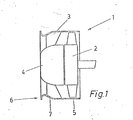
- the figures schematically show a cross section through an axial fan 1, consisting of an impeller 2, a guide impeller 3, the hub 4 and a housing jacket 5.
- the impeller 2 is mounted in a manner known per se with the aid of a V-belt driven by the crankshaft or an intermediate shaft of the internal combustion engine, not shown.
- the guide wheel 3 is shrunk with the hub 4 into the housing shell 5.
- the housing shell 5 is no longer in the inlet area 6 - as was previously usual -. Protrudes due to the inlet radius on the contour of the fan shell section in the region of the impeller 2, the inlet radius 6 shown in Figure 1 is retracted so that the leading edge of the fan casing contour g facilitated with its section in the impeller area. This measure creates a diagonal flow in front of or in the area of the stator 3.
- the impeller 2 itself is flowed through axially. Because of this training, the flow conditions are additionally improved.
- the outlet area 7 of the inlet radius 6, which is at the rear in the direction of flow, is designed to extend into the region of the guide wheel 3 in the case of axially small-sized fans.
- the guide vane 3 is fastened in the blower jacket 5 by shrinking, it is difficult to provide the outlet area 7 as far as into the guide vane area 3, since then reduced adhesive forces can occur during and after the shrinking. In this case, it is then better to move the inlet radius 6 axially forward with an outlet area 7 to such an extent that there is no longer any deformation of the blower jacket 5 in the stator area 3.
- FIG. 2 and 3 differs from that of FIG. 1 in that an insert 8 is provided instead of the constriction.
- the blower jacket 5 has both in the inlet area and in the area of the Impeller 2 has a constant outer circumference.
- the rear region 7 of the insert 8 in the direction of flow in the case of axially small fans is designed to extend into the region of the guide wheel 3.
- the guide vane 3 is fastened in the blower casing 5 by shrinking, it makes sense to provide the insert 8 as far as into the guide vane region 3 and to manufacture both in one piece.
- the insert 8 Due to the front likewise rounded edge 9 of the insert 8 and its gripping around the front edge of the blower jacket 5, a flow-optimized inlet area is created without changing the outside diameter of the blower jacket.
- the insert 8 is easy and safe to attach due to this training, for. B. by shrinking or radially arranged screws.
- FIG 3 shows a partial cross section of the insert 8 with its front edge 9 and the shoulder 10 for receiving the blower jacket 5.
Landscapes
- Engineering & Computer Science (AREA)
- Mechanical Engineering (AREA)
- General Engineering & Computer Science (AREA)
- Structures Of Non-Positive Displacement Pumps (AREA)
Priority Applications (1)
| Application Number | Priority Date | Filing Date | Title |
|---|---|---|---|
| AT83110032T ATE23911T1 (de) | 1982-11-15 | 1983-10-07 | Axialgeblaese fuer luftgekuehlte brennkraftmaschine. |
Applications Claiming Priority (4)
| Application Number | Priority Date | Filing Date | Title |
|---|---|---|---|
| DE3242185 | 1982-11-15 | ||
| DE3242186 | 1982-11-15 | ||
| DE19823242186 DE3242186A1 (de) | 1982-11-15 | 1982-11-15 | Luftgekuehlte brennkraftmaschinen |
| DE19823242185 DE3242185A1 (de) | 1982-11-15 | 1982-11-15 | Luftgekuehlte brennkraftmaschine |
Publications (2)
| Publication Number | Publication Date |
|---|---|
| EP0108922A1 true EP0108922A1 (fr) | 1984-05-23 |
| EP0108922B1 EP0108922B1 (fr) | 1986-11-26 |
Family
ID=25805788
Family Applications (1)
| Application Number | Title | Priority Date | Filing Date |
|---|---|---|---|
| EP83110032A Expired EP0108922B1 (fr) | 1982-11-15 | 1983-10-07 | Ventilateur axial pour machine à carburant refroidi par l'air |
Country Status (2)
| Country | Link |
|---|---|
| EP (1) | EP0108922B1 (fr) |
| DE (1) | DE3367962D1 (fr) |
Cited By (1)
| Publication number | Priority date | Publication date | Assignee | Title |
|---|---|---|---|---|
| EP1830072A2 (fr) * | 2006-03-01 | 2007-09-05 | Behr GmbH & Co. KG | Châssis de ventilateur pour transmetteur thermique et dispositif d'un ventilateur axial dans un châssis de ventilateur |
Families Citing this family (1)
| Publication number | Priority date | Publication date | Assignee | Title |
|---|---|---|---|---|
| US6827547B2 (en) | 2003-01-29 | 2004-12-07 | Borgwarner Inc. | Engine cooling fan having improved airflow characteristics |
Citations (2)
| Publication number | Priority date | Publication date | Assignee | Title |
|---|---|---|---|---|
| FR1360211A (fr) * | 1963-03-04 | 1964-05-08 | A De Jong N V | Ventilateur axial |
| FR2386706A1 (fr) * | 1977-04-05 | 1978-11-03 | Neu Ets | Perfectionnement aux ventilateurs helicoides |
-
1983
- 1983-10-07 DE DE8383110032T patent/DE3367962D1/de not_active Expired
- 1983-10-07 EP EP83110032A patent/EP0108922B1/fr not_active Expired
Patent Citations (2)
| Publication number | Priority date | Publication date | Assignee | Title |
|---|---|---|---|---|
| FR1360211A (fr) * | 1963-03-04 | 1964-05-08 | A De Jong N V | Ventilateur axial |
| FR2386706A1 (fr) * | 1977-04-05 | 1978-11-03 | Neu Ets | Perfectionnement aux ventilateurs helicoides |
Cited By (2)
| Publication number | Priority date | Publication date | Assignee | Title |
|---|---|---|---|---|
| EP1830072A2 (fr) * | 2006-03-01 | 2007-09-05 | Behr GmbH & Co. KG | Châssis de ventilateur pour transmetteur thermique et dispositif d'un ventilateur axial dans un châssis de ventilateur |
| EP1830072A3 (fr) * | 2006-03-01 | 2008-03-26 | Behr GmbH & Co. KG | Châssis de ventilateur pour transmetteur thermique et dispositif d'un ventilateur axial dans un châssis de ventilateur |
Also Published As
| Publication number | Publication date |
|---|---|
| DE3367962D1 (en) | 1987-01-15 |
| EP0108922B1 (fr) | 1986-11-26 |
Similar Documents
| Publication | Publication Date | Title |
|---|---|---|
| DE3779462T2 (de) | Wechselstromgenerator fuer kraftfahrzeug. | |
| DE2855909C2 (de) | Axial oder halbaxialdurchströmtes Lauf- oder Vorleitrad mit in Strömungsrichtung zunehmendem Nabendurchmesser, insbesondere zur Kühlung von Brennkraftmaschinen in Fahrzeugen | |
| DE3907565C2 (fr) | ||
| DE3227698C2 (fr) | ||
| DE4438182A1 (de) | Axialkleinventilator | |
| WO2015124487A2 (fr) | Ventilateur comprenant un rotor doté de pales mobiles | |
| DE3137114A1 (de) | Axialgeblaese, insbesondere fuer kraftfahrzeuge | |
| DE7818243U1 (de) | Kraftfahrzeug mit luftgekühltem Kühler | |
| DE2849675A1 (de) | Kuehlanlage fuer brennkraftmaschinen, insbesondere in fahrzeugen | |
| DE102008000168A1 (de) | Gebläseanordnung mit Vordrallerzeuger | |
| WO2010015466A1 (fr) | Turbocompresseur comprenant une tôle rapportée | |
| EP1757814A1 (fr) | Compresseur centrifuge | |
| DE2939385A1 (de) | Radialgeblaese, insbesondere fuer heiz- oder klimaanlagen von fahrzeugen | |
| DE9016496U1 (de) | Axiallüfter | |
| DE1403032A1 (de) | Zentrifugalgeblaese | |
| DE2530742A1 (de) | Geraeuscharme kuehlanlage, insbesondere fuer kraftfahrzeuge | |
| EP0108922B1 (fr) | Ventilateur axial pour machine à carburant refroidi par l'air | |
| DE3242185A1 (de) | Luftgekuehlte brennkraftmaschine | |
| DE3242186A1 (de) | Luftgekuehlte brennkraftmaschinen | |
| DE2633781B2 (de) | Radialventilator mit hoher Druckziffer | |
| DE20317171U1 (de) | Lüftergehäuse | |
| DE19638185A1 (de) | Wasserpumpe | |
| DE1576708A1 (de) | Kuehleinrichtung fuer fluessigkeitsgekuehlte Motoren | |
| EP0452518B1 (fr) | Système de refroidissement comprenant un ventilateur axial entraîné par un moteur électrique, utilisé en particulier dans un véhicule automobile | |
| DE1650864B1 (de) | Einstufiger hydrodynamischer drehmomentwandler mit zentrifugal durchstroemtem unmittelbar hintereinander liegendem pumpen und turbinengitter mit schaufellosen kanalkruemmern und zentripedal durchstroemtem leitradgitter |
Legal Events
| Date | Code | Title | Description |
|---|---|---|---|
| PUAI | Public reference made under article 153(3) epc to a published international application that has entered the european phase |
Free format text: ORIGINAL CODE: 0009012 |
|
| AK | Designated contracting states |
Designated state(s): AT DE FR GB IT |
|
| 17P | Request for examination filed |
Effective date: 19840515 |
|
| GRAA | (expected) grant |
Free format text: ORIGINAL CODE: 0009210 |
|
| AK | Designated contracting states |
Kind code of ref document: B1 Designated state(s): AT DE FR GB IT |
|
| REF | Corresponds to: |
Ref document number: 23911 Country of ref document: AT Date of ref document: 19861215 Kind code of ref document: T |
|
| ITF | It: translation for a ep patent filed | ||
| REF | Corresponds to: |
Ref document number: 3367962 Country of ref document: DE Date of ref document: 19870115 |
|
| ET | Fr: translation filed | ||
| PLBE | No opposition filed within time limit |
Free format text: ORIGINAL CODE: 0009261 |
|
| STAA | Information on the status of an ep patent application or granted ep patent |
Free format text: STATUS: NO OPPOSITION FILED WITHIN TIME LIMIT |
|
| 26N | No opposition filed | ||
| PGFP | Annual fee paid to national office [announced via postgrant information from national office to epo] |
Ref country code: AT Payment date: 19890911 Year of fee payment: 7 |
|
| PGFP | Annual fee paid to national office [announced via postgrant information from national office to epo] |
Ref country code: FR Payment date: 19890912 Year of fee payment: 7 |
|
| PGFP | Annual fee paid to national office [announced via postgrant information from national office to epo] |
Ref country code: DE Payment date: 19891102 Year of fee payment: 7 |
|
| PGFP | Annual fee paid to national office [announced via postgrant information from national office to epo] |
Ref country code: GB Payment date: 19900912 Year of fee payment: 8 |
|
| PG25 | Lapsed in a contracting state [announced via postgrant information from national office to epo] |
Ref country code: AT Effective date: 19901007 |
|
| ITTA | It: last paid annual fee | ||
| PG25 | Lapsed in a contracting state [announced via postgrant information from national office to epo] |
Ref country code: FR Effective date: 19910628 |
|
| PG25 | Lapsed in a contracting state [announced via postgrant information from national office to epo] |
Ref country code: DE Effective date: 19910702 |
|
| REG | Reference to a national code |
Ref country code: FR Ref legal event code: ST |
|
| PG25 | Lapsed in a contracting state [announced via postgrant information from national office to epo] |
Ref country code: GB Effective date: 19911007 |
|
| GBPC | Gb: european patent ceased through non-payment of renewal fee |