EP0108211A2 - Mehrplattenkondensatoren und Verfahren zu ihrer Herstellung - Google Patents
Mehrplattenkondensatoren und Verfahren zu ihrer Herstellung Download PDFInfo
- Publication number
- EP0108211A2 EP0108211A2 EP83108572A EP83108572A EP0108211A2 EP 0108211 A2 EP0108211 A2 EP 0108211A2 EP 83108572 A EP83108572 A EP 83108572A EP 83108572 A EP83108572 A EP 83108572A EP 0108211 A2 EP0108211 A2 EP 0108211A2
- Authority
- EP
- European Patent Office
- Prior art keywords
- capacitor
- solder
- metal
- plates
- stack
- Prior art date
- Legal status (The legal status is an assumption and is not a legal conclusion. Google has not performed a legal analysis and makes no representation as to the accuracy of the status listed.)
- Granted
Links
- 239000003990 capacitor Substances 0.000 title claims abstract description 138
- 238000000034 method Methods 0.000 title claims abstract description 51
- 229910000679 solder Inorganic materials 0.000 claims abstract description 85
- 239000007769 metal material Substances 0.000 claims abstract description 5
- 229910052751 metal Inorganic materials 0.000 claims description 71
- 239000002184 metal Substances 0.000 claims description 70
- 239000000919 ceramic Substances 0.000 claims description 36
- 238000005470 impregnation Methods 0.000 claims description 22
- 229910001338 liquidmetal Inorganic materials 0.000 claims description 21
- 238000010304 firing Methods 0.000 claims description 20
- 239000000758 substrate Substances 0.000 claims description 19
- 239000000463 material Substances 0.000 claims description 13
- 238000001465 metallisation Methods 0.000 claims description 13
- 229910010293 ceramic material Inorganic materials 0.000 claims description 12
- 238000004049 embossing Methods 0.000 claims description 8
- 238000001704 evaporation Methods 0.000 claims description 8
- 239000002245 particle Substances 0.000 claims description 7
- 238000005245 sintering Methods 0.000 claims description 7
- 230000008020 evaporation Effects 0.000 claims description 6
- 238000011049 filling Methods 0.000 claims description 6
- 238000010438 heat treatment Methods 0.000 claims description 6
- 238000012545 processing Methods 0.000 claims description 6
- 238000003491 array Methods 0.000 claims description 5
- 239000011248 coating agent Substances 0.000 claims description 5
- 238000000576 coating method Methods 0.000 claims description 5
- 238000002844 melting Methods 0.000 claims description 5
- 230000008018 melting Effects 0.000 claims description 5
- 238000004080 punching Methods 0.000 claims description 5
- 239000003989 dielectric material Substances 0.000 claims description 4
- 239000011261 inert gas Substances 0.000 claims description 4
- 238000005304 joining Methods 0.000 claims description 4
- 239000007788 liquid Substances 0.000 claims description 4
- 230000015572 biosynthetic process Effects 0.000 claims description 3
- 238000005520 cutting process Methods 0.000 claims description 3
- 238000013461 design Methods 0.000 claims description 3
- 239000000155 melt Substances 0.000 claims description 3
- 239000007787 solid Substances 0.000 claims description 3
- 238000003754 machining Methods 0.000 claims description 2
- 239000011368 organic material Substances 0.000 claims description 2
- 238000004519 manufacturing process Methods 0.000 abstract description 15
- 230000008569 process Effects 0.000 description 23
- 239000010408 film Substances 0.000 description 13
- 239000004020 conductor Substances 0.000 description 6
- PXHVJJICTQNCMI-UHFFFAOYSA-N Nickel Chemical compound [Ni] PXHVJJICTQNCMI-UHFFFAOYSA-N 0.000 description 5
- 238000003475 lamination Methods 0.000 description 5
- 230000008901 benefit Effects 0.000 description 4
- 239000003985 ceramic capacitor Substances 0.000 description 4
- 238000001816 cooling Methods 0.000 description 4
- 238000005272 metallurgy Methods 0.000 description 4
- 229910052802 copper Inorganic materials 0.000 description 3
- 238000010030 laminating Methods 0.000 description 3
- 229910052759 nickel Inorganic materials 0.000 description 3
- 238000004806 packaging method and process Methods 0.000 description 3
- 238000009736 wetting Methods 0.000 description 3
- QAOWNCQODCNURD-UHFFFAOYSA-N Sulfuric acid Chemical compound OS(O)(=O)=O QAOWNCQODCNURD-UHFFFAOYSA-N 0.000 description 2
- KKEYFWRCBNTPAC-UHFFFAOYSA-N Terephthalic acid Chemical compound OC(=O)C1=CC=C(C(O)=O)C=C1 KKEYFWRCBNTPAC-UHFFFAOYSA-N 0.000 description 2
- 230000001464 adherent effect Effects 0.000 description 2
- 238000009826 distribution Methods 0.000 description 2
- 238000005516 engineering process Methods 0.000 description 2
- 230000006872 improvement Effects 0.000 description 2
- 230000008595 infiltration Effects 0.000 description 2
- 238000001764 infiltration Methods 0.000 description 2
- 150000002739 metals Chemical class 0.000 description 2
- 239000000843 powder Substances 0.000 description 2
- OKTJSMMVPCPJKN-UHFFFAOYSA-N Carbon Chemical compound [C] OKTJSMMVPCPJKN-UHFFFAOYSA-N 0.000 description 1
- 229910000881 Cu alloy Inorganic materials 0.000 description 1
- 229910001252 Pd alloy Inorganic materials 0.000 description 1
- 241001604129 Polydactylus Species 0.000 description 1
- 230000009471 action Effects 0.000 description 1
- 238000005275 alloying Methods 0.000 description 1
- 229910052782 aluminium Inorganic materials 0.000 description 1
- PNEYBMLMFCGWSK-UHFFFAOYSA-N aluminium oxide Inorganic materials [O-2].[O-2].[O-2].[Al+3].[Al+3] PNEYBMLMFCGWSK-UHFFFAOYSA-N 0.000 description 1
- 230000001668 ameliorated effect Effects 0.000 description 1
- 238000013459 approach Methods 0.000 description 1
- QVGXLLKOCUKJST-UHFFFAOYSA-N atomic oxygen Chemical compound [O] QVGXLLKOCUKJST-UHFFFAOYSA-N 0.000 description 1
- 239000011230 binding agent Substances 0.000 description 1
- 229910052799 carbon Inorganic materials 0.000 description 1
- 239000000969 carrier Substances 0.000 description 1
- 229910052804 chromium Inorganic materials 0.000 description 1
- 238000002485 combustion reaction Methods 0.000 description 1
- 239000002131 composite material Substances 0.000 description 1
- 150000001875 compounds Chemical class 0.000 description 1
- 238000010276 construction Methods 0.000 description 1
- 238000005336 cracking Methods 0.000 description 1
- 238000000280 densification Methods 0.000 description 1
- 230000001419 dependent effect Effects 0.000 description 1
- 238000011161 development Methods 0.000 description 1
- 230000018109 developmental process Effects 0.000 description 1
- 238000004090 dissolution Methods 0.000 description 1
- 239000007772 electrode material Substances 0.000 description 1
- 239000002241 glass-ceramic Substances 0.000 description 1
- 229910052737 gold Inorganic materials 0.000 description 1
- 229910052745 lead Inorganic materials 0.000 description 1
- 230000000873 masking effect Effects 0.000 description 1
- 239000000203 mixture Substances 0.000 description 1
- 238000012986 modification Methods 0.000 description 1
- 230000004048 modification Effects 0.000 description 1
- 229910052750 molybdenum Inorganic materials 0.000 description 1
- 229910000480 nickel oxide Inorganic materials 0.000 description 1
- 229910000510 noble metal Inorganic materials 0.000 description 1
- 230000003647 oxidation Effects 0.000 description 1
- 238000007254 oxidation reaction Methods 0.000 description 1
- GNRSAWUEBMWBQH-UHFFFAOYSA-N oxonickel Chemical compound [Ni]=O GNRSAWUEBMWBQH-UHFFFAOYSA-N 0.000 description 1
- 229910052760 oxygen Inorganic materials 0.000 description 1
- 239000001301 oxygen Substances 0.000 description 1
- 229910052763 palladium Inorganic materials 0.000 description 1
- 235000012771 pancakes Nutrition 0.000 description 1
- 238000012216 screening Methods 0.000 description 1
- 229910052709 silver Inorganic materials 0.000 description 1
- 239000010409 thin film Substances 0.000 description 1
- 229910052718 tin Inorganic materials 0.000 description 1
- -1 titanate compound Chemical class 0.000 description 1
- 229910052719 titanium Inorganic materials 0.000 description 1
- 238000012546 transfer Methods 0.000 description 1
- 229910052720 vanadium Inorganic materials 0.000 description 1
- 238000009834 vaporization Methods 0.000 description 1
- 229910052725 zinc Inorganic materials 0.000 description 1
Images


Classifications
-
- H—ELECTRICITY
- H05—ELECTRIC TECHNIQUES NOT OTHERWISE PROVIDED FOR
- H05K—PRINTED CIRCUITS; CASINGS OR CONSTRUCTIONAL DETAILS OF ELECTRIC APPARATUS; MANUFACTURE OF ASSEMBLAGES OF ELECTRICAL COMPONENTS
- H05K3/00—Apparatus or processes for manufacturing printed circuits
- H05K3/30—Assembling printed circuits with electric components, e.g. with resistor
- H05K3/32—Assembling printed circuits with electric components, e.g. with resistor electrically connecting electric components or wires to printed circuits
- H05K3/34—Assembling printed circuits with electric components, e.g. with resistor electrically connecting electric components or wires to printed circuits by soldering
- H05K3/341—Surface mounted components
- H05K3/3431—Leadless components
- H05K3/3442—Leadless components having edge contacts, e.g. leadless chip capacitors, chip carriers
-
- H—ELECTRICITY
- H01—ELECTRIC ELEMENTS
- H01G—CAPACITORS; CAPACITORS, RECTIFIERS, DETECTORS, SWITCHING DEVICES, LIGHT-SENSITIVE OR TEMPERATURE-SENSITIVE DEVICES OF THE ELECTROLYTIC TYPE
- H01G4/00—Fixed capacitors; Processes of their manufacture
- H01G4/30—Stacked capacitors
-
- H—ELECTRICITY
- H05—ELECTRIC TECHNIQUES NOT OTHERWISE PROVIDED FOR
- H05K—PRINTED CIRCUITS; CASINGS OR CONSTRUCTIONAL DETAILS OF ELECTRIC APPARATUS; MANUFACTURE OF ASSEMBLAGES OF ELECTRICAL COMPONENTS
- H05K2201/00—Indexing scheme relating to printed circuits covered by H05K1/00
- H05K2201/09—Shape and layout
- H05K2201/09209—Shape and layout details of conductors
- H05K2201/09654—Shape and layout details of conductors covering at least two types of conductors provided for in H05K2201/09218 - H05K2201/095
- H05K2201/09663—Divided layout, i.e. conductors divided in two or more parts
-
- Y—GENERAL TAGGING OF NEW TECHNOLOGICAL DEVELOPMENTS; GENERAL TAGGING OF CROSS-SECTIONAL TECHNOLOGIES SPANNING OVER SEVERAL SECTIONS OF THE IPC; TECHNICAL SUBJECTS COVERED BY FORMER USPC CROSS-REFERENCE ART COLLECTIONS [XRACs] AND DIGESTS
- Y02—TECHNOLOGIES OR APPLICATIONS FOR MITIGATION OR ADAPTATION AGAINST CLIMATE CHANGE
- Y02P—CLIMATE CHANGE MITIGATION TECHNOLOGIES IN THE PRODUCTION OR PROCESSING OF GOODS
- Y02P70/00—Climate change mitigation technologies in the production process for final industrial or consumer products
- Y02P70/50—Manufacturing or production processes characterised by the final manufactured product
-
- Y—GENERAL TAGGING OF NEW TECHNOLOGICAL DEVELOPMENTS; GENERAL TAGGING OF CROSS-SECTIONAL TECHNOLOGIES SPANNING OVER SEVERAL SECTIONS OF THE IPC; TECHNICAL SUBJECTS COVERED BY FORMER USPC CROSS-REFERENCE ART COLLECTIONS [XRACs] AND DIGESTS
- Y10—TECHNICAL SUBJECTS COVERED BY FORMER USPC
- Y10T—TECHNICAL SUBJECTS COVERED BY FORMER US CLASSIFICATION
- Y10T29/00—Metal working
- Y10T29/43—Electric condenser making
- Y10T29/435—Solid dielectric type
Definitions
- This invention relates to capacitors and methods of making capacitors but is more particularly concerned with ceramic capacitors for LSI chip packaging modules.
- U.S. patent 4,349,862 shows a laminated capacitor bonded to a chip carrier by means of solder balls connected to individual capacitor plates.
- U.S. patent 4,246,625 shows a laminated capacitor with terminals on the ends bonded to the plates of the capacitor.
- U.S. patent 4,189,760 describes a method of making a multilayered monolithic capacitor by using an electrode forming material including nickel oxide powder which is included in the laminated structure when it is fired. After firing, the nickel is removed by dissolving the nickel in a solution such as dilute sulfuric acid. After refiring, the structure contains voids which can be filled with suitable electrode material applied by means of a combination of capillary action and pressure. Fusible metal such as solder can be used.
- U.S. patent 3,852,877 describes a method of forming vias from a metallizing medium which includes "metals and compounds which convert to a metal during firing.
- the sheets are stacked in registry, laminated into a monolithic structure and heated in a reducing atmosphere to sinter the ceramic to a dense body, and simultaneously fire the metallizing media to form an adherent metal capillary within the body.
- a high conductivity, low melting point conductor fills the capillary thereby forming a highly conductive circuit member in the multilevel ceramic structure.
- the metallizing media can be in the form of a paste.
- U.S. patent 3,235,939 shows formation of laminated capacitors and then applying metallization to the edge of the laminated structure to give parallel connections of each end of the stack so that the plates can be bussed together. The laminated capacitor is then attached to a set of leads with one at each end of the stack.
- U .S. patents 4,030,004, 3,829,356, 3,772,748, 3,965,552 and 3,679,950 disclose methods for manufacturing MLC circuits and capacitors. Use is made of a paste that defines the circuit patterns within the structure. The paste volatizes during firing leaving voids within the structure. These voids are then filled with molten metal to form conductors within the substrate.
- each of the capacitors is terminated on each end with a single lead.
- the capacitor tabs are connected to the buss bars which are connected to the LSI chip carrier by means of multiple C-4 balls, in a manner which is substantially enhanced by the instant invention, which eliminates the solder balls and substitutes the solder bars of this invention therefor.
- D. A. Chance and D. L. Wilcox "Capillary-Infiltrated Conductors in Ceramics" Metallurgical Transactions Vol. 2, 733-740 (Mar. 1971) describe infiltration of high conductivity liquid metals into partially metallized capillaries in ceramic structures to form highly conductive lines in the structure. Here oxidation of the previously applied metal must be avoided by operating in the absence of oxygen, etc.
- MLC capacitors have been developed with edge connections, and with low inductance connections.
- MLC chip carriers have been provided with vias and lines which can be fabricated by a process of infiltration.
- fabrication has been achieved by impregnation of ceramic structures with liquid metal.
- the improvements of this invention over the prior art are to afford a low inductance bar contact arrangement, fabrication of capacitor plates and connections by means of impregnation, and simplified processing procedures for achieving those ends.
- An object of this invention is to provide a large scale integrated packaging circuit component by employing a structure and processes for fabricating a metal impregnated discrete capacitor with low inductance contacts.
- the fabrication of a laminated form of multilayered ceramic (MLC) metal and ceramic capacitor is usually accomplished by the cofiring of metallic and ceramic materials.
- MLC multilayered ceramic
- the problem is that ceramics are generally oxidized metallic elements and there is a compromise in the selection of the metal electrodes such that the metal neither oxidizes in the firing ambient, nor does it melt at the firing temperature, yet enters compatibly with the ceramic.
- a high dielectric constant material which is usually composed of a titanate compound, requires fabrication in an environment which is nonreducing at temperatures exceeding 1000#C. This normally limits the choice of metals which can be used in the cofired metal to the noble metals such as an Ag-Pd alloy.
- Provisions for a low inductance power supply system such as that necessary for high current and fast switching circuits require low inductance current paths both within the capacitor and interconnections from the capacitor to the integrated circuit chips.
- This invention provides such low inductance current paths which reduce inductance by affording current flow in opposing directions in multiple adjacent current paths.
- the inductance is reduced one to two orders of magnitude below a comparable and typical MLC capacitor with two terminals at opposing ends of the capacitor.
- metallic pastes containing Mo, Cu, Pd, Ag, etc. are screened onto green ceramic sheets in accordance with the current state of the art. These sheets are then stacked, laminated and fired.
- the metallic pastes sinter to become a three-dimensional conductive network of individual conductive segments and lines insulated from each other by the surrounding dielectric material.
- One difficulty with the firing step is that it requires cofiring all materials within the MLC structure in an atmosphere which reduces the metal but oxidizes the ceramic sufficiently to maintain the desired electrical resistance and dielectric constant. See commonly assigned U.S.
- a capacitor suitable for mounting on a carrier substrate having two arrays of elongate mounting pads said capacitor comprising a multiplicity of capacitor plates in face-to-face relationship but separated by laters of dielectric materials, characterised in that a first set comprising alternate capacitor plates are connected to a first array of elongate, bar contacts and a second set of the intervening capacitor plates are connected to a second array of elongate var contacts, the two arrays of elongate bar contacts on the capacitor being positioned an arranged so that the capacitor can be physically and electrically connected to the carrier substrate by joining the bar contacts to the elongate mounting pads on the carrier.
- a device comprising the combination of a chip carrier for large scale integrated circuit chips with a laminated capacitor joined to the surface of said carrier adjacent to positions where chips are or are to be located, said laminated capacitor including a multiplicity of capacitor plates, characterised in that said capacitor is bonded to said chip carrier with an array of solder bars comprising an elongated strip of metallic material each of said bars being connected to one or other of the two sets of capacitor plates in said laminated capacitor by means of tab connections on said plates so that each of said plates is connected by a plurality of tabs to a plurality of said solder bars.
- the plates and the tabs have been formed by means of introducing (forcing) metal into the laminated structure and the solder bars have a rounded contour on the surface extending away from the chip.
- the substrate includes a set of elongated pads bonded along their length to the solder bars.
- the solder bars are formed by embossing of grooves into green ceramic material. At least one of the solder bars is formed in a recess in the laminated capacitor whereby a strong mechanical arrangement is provided.
- a method for forming a laminated capacitor comprising a) punching individual layers of green ceramic material having metallic material for forming tabs and/or capacitor plates on screened thereon in selected areas of the layers in a predetermined pattern, b) stacking the layers of green ceramic material upon one another to form a stack and sintering the green stack, and c) forming bars on the edge of the stack.
- the method of forming bars on the edge of the stack by means of the steps including a) coating the edge of the sheets with a metal film, with openings being left in the metal film for introduction of liquid metal into openings appropriate for formation of said tabs and/or capacitor plates, b) defining bar patterns on the capacitor by cutting portions of the metal film to form bar portions on the edge coated with the metal film, or forming embossed patterns on the surface prior to firing in step b, c) impregnation of molten metal into the tab openings to form tabs and capacitor plates also at will in accordance with predetermined design parameters.
- the bars are formed on the edge of the stack by applying a mask to the edge of the stack and applying metal to the edge through slots in the mask forming bar patterns.
- the bars are formed by evaporating metal into the slots.
- the metal comprises adhesion metal, solder wettable metal and solder evaporated in sequence into the slots.
- the tabs and/or plates in the stack and the bars are formed by heating the product of one of the above methods in an evacuated chamber to the melting point of the solder, back filling the chamber with an inert gas forcing solder into the tabs and/or plates in the stack providing impregnation of metal solder in the liquid state from the slots in the mask onto the edge of the stack and into the tabs and/or plates.
- the solder bar includes enough solder to join the bar to a mounting pad subsequent to the impregnation step.
- a method for forming a capacitor from a laminated stack of ceramic sheets comprising a) forming a stack of ceramic green sheets with patterns of (1) metallization or (2) alternatively a screened layer of paste primarily containing combustible volatile elements formed on the surface of the sheets, b) embossing the stack of green sheets with an array of grooves on the edge of the stack, c) firing the stack to produce a partially completed capacitor, d) coating the embossed edge of the stack with a metal film e) machining the edge of the stack to remove the distal portions of the film projecting from the grooves to separate the metal film into segments contained solely within the depressions of the grooves, f) if the electrode cavities are unfilled because combustible volatile paste was used in step a (2), then a step follows of impregnation of the metal coated grooves with
- the product of one of the above processes is reflowed to form rounded contours on the solder bars. It is inverted and joined to a metallized substrate.
- the slots and the capacitor plates are prepared for filling and the metallization material comprises a premetallization substitute comprising ceramic particles and an organic material, and after firing the structure as above, a) the structure is placed in a vacuum processing chamber and the chamber is evacuated, b) the structure is dipped into a liquid metal bath, c) the chamber is pressurized to drive the liquid metal into the openings in the structure to fill the cavities within the structure to form capacitor plates, vias, and/or tabs.
- the solid metal is applied to the slots and upon heating and pressurization the metal melts and is forced into the cavities which remain thereby forming metallization in the cavities.
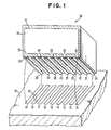
- FIG. 1 shows a substrate 10 carrying an array of bar contacts 11 to 19 which are supported on the surface of substrate 10.
- Substrate 10 comprises a ceramic module incorporating conductive circuit lines and vias such as those shown in commonly assigned U.S. patent 4,349,862 for “Capacitive Chip Carrier and Multilayer Ceramic Capacitors and U.S. patent 4,328,530 of Bajorek et al for "Multiple Layer, Ceramic Carrier for High Switching Speed VLSI Chips".
- Capacitor 38 comprises a laminated stack of vertical conductor planes or capacitor plates such as plate 30 separated by means of dielectric layers 41 which extend beyond the edges of the plates 30, etc.
- tabs 31 and 35 On the lower edge of plate 30 are shown tabs 31 and 35 which are provided for the purpose of connecting electrically to the negative (reference voltage) transverse solder bars 20, 22, 24, 26 and 28 with the positive solder bars 21, 23, 25 and 27 insulated from the plate 30 but connected to the positive plates beneath plate 30 in the laminated structure of capacitor 38.
- the capacitor plates have many electrical connection sites, i.e. the tabs 31-36 of plate 30 and plates below plate 30 which are interconnected to share a common voltage.
- FIGS. 2.1 - 2.3 show the plate 30 with tabs 31-35 and plate 40 which is a plate having voltage Vl, with tabs 41-44 which connect through the solder bars 20-28 to a source with the appropriate voltage.
- the plates 30 and 40 and their associated tabs are separated mechanically and are isolated electrically by means of the dielectric separator sheet 41.
- the structure shown in FIGS. 1 and 2.1 to 2.3 uses the bar contact metallurgy (BCM) and may use the solder impregnation process, to simplify the process of fabrication considerably, when manufacturing a low inductance capacitor 38 as a component manufactured in accordance with this invention.
- BCM bar contact metallurgy
- the soldered contacts of the capacitor 38 use the shorting bars 20 to 28 connecting across the common tabs of the low inductance discrete capacitors 30.
- the bars 20-28 on the capacitor are soldered and reflowed onto matching metal bars 11-19 on the substrate 10.
- FIG. 3 shows a punch and lamination die 50 with a plurality of openings 54 for punched portions 52 of the green sheet 53 which are punched out by the punch tool 51 carrying punch elements 55. -Portions are pushed down by force F into the openings 54 by the punch elements 55. Punched areas 57 remain where portions 52 have been punched and pushed down into openings 54.
- the green sheet 53 is printed with metallized paste 56 or combustible paste (suitable for impregnation) with the tabs 31-35 (or 41-44 from FIGS. 2.1-2.3) shown on the left.
- the normally used metal paste is replaced by a paste containing particles (e.g., carbon or terephthalic acid) which volatilizes completely during burnoff, forming a planar cavity 83 between the dielectric layers 84.
- a coarse ceramic powder may be included in the paste, which after firing, leaves a porous cavity 83 with the particles separating the planes of dielectric 84.
- the capacitors After sintering the capacitors are stacked and then the edges are coated with a blanket of metallization on the surface with layers of an adherent metal (Cr, Ti, V, etc. about 100 nm thick) and a solder wettable metal (Cu, Ni, Au, etc. about 500 nm thick).
- the thickness of the metallic composite 58 is designed to allow long contact with molten solder without being depleted by alloying or dissolution but of insufficient thickness to clog the tab openings 59 of each porous cavity 83. The relative sizes are shown in FIG. 4.
- a saw is used to remove portions of the blanket 58 of metallization and thus portions of the capacitor between the tab arrays 61.
- the structure can be embossed as described below in connection with FIG. 6.1 - 6.5.
- the impregnation of molten solder is accomplished by applying vacuum, immersing the capacitors in molten solder, repressurizing to impregnate solder and withdrawing the capacitor from the solder. On cooling finished capacitors are obtained as shown in FIG. 1.
- An alternate process for impregnation is by decal transfer of solder. Sufficient solder on a decal is transferred to the tabs by melting in a vacuum. On pressurizing while still-molten, the solder is driven into the capacitor leaving excess solder on the tabs for joining as is shown in FIG. 7.
- FIG. 5 illustrates an alternate post-sintering process which uses more sophisticated alignment masks 67 and carrier jigs (comprising laminated and brazed alignment plates 69) to hold the capacitor chips 38 in place.
- Mask 67 is brazed to alignment plates 69.
- the mask 67 which serves as an evaporation mask and jigs 69 are shown in FIG. 5.
- the adhesion metal, solder wettable metal and solder are evaporated in sequence through slots 68 over the tabs. On heating above the melting point of the solder, back filling with an inert gas for impregnation of areas 83 with liquid metal solder and cooling down, the contact metallurgy process is completed. In this case saw cutting for bar definition is unnecessary.
- Appropriate tolerances for the capacitors are a about 0.025 mm perpendicular to the solder bars and 0.05 mm parallel to the solder bars.
- the bar location is about 0.125 mm from the edge of the capacitor chip.
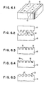
- FIGS. 6.1 - 6.5 show a capacitor chip 60 containing electrodes (or planar cavities 83 as in FIG. 5 to be filled with metal). This simplifies the fabrication of the capacitor by incorporating bar contact (20-28 in FIG. 1) rather than C-4 solder ball joints as the connections between the capacitor electrodes and the substrates. The result of use of this procedure is that the joints produced have improved fatigue resistance.
- FIG. 6.1 shows a capacitor comprising a green stack 60 of laminated layers of ceramic and metal layers with the tabs 61 of the capacitor plates shown on the upper surface of the laminated structure.
- the tabs 61 are to be formed by means of providing them on the plates (30, 40 in FIGS. 2.1 - 2.3) or by means of providing planar cavities 83 and filling them with metal.
- the cavities are formed by the process described below in connection with FIG. 7.
- FIG. 6.2 the green capacitor stack 60 is shown after it has been embossed with rows 62 extending back into the page by means of the embossing tool 63 having the required pattern of grooves, which is shown.
- the resulting structure is a set of parallel rows of grooves 62 on the upper surface of the capacitor 60 aligned with the rows 59 of tabs 61.
- the rows 59 are to be interconnected by means of the solder bar bus lines in accordance with this invention as described above.
- FIG. 6.1 shows the stack of capacitor laminations after the laminating process has been completed, it is possible to combine the lamination. process with the embossing of solder bar grooves in FIG. 6.2 into a unitary process with the upper surface (which would be lying on its side in the laminating press) of the laminations exposed to the grooved embossing tool during the laminating process.
- the capacitor stack 60 is fired to produce a partially completed capacitor chip 38.
- the embossed surface of the capacitor 60 is now coated with a blanket layer of metallic film 64 leaving rows of shallower and narrower grooves 65 overlying grooves 62 which are partially filled with metallic film 64 and coated with metallic film 64 on the walls of the grooves.
- Film 64 can be deposited by means of evaporation although for a capacitor containing electrodes, other techniques such as screening of metal through a silk screen may be appropriate to this process.
- the embossed surface of the capacitor chip 38 is lapped thereby removing the projecting.surfaces of chip 38 revealing the surfaces 66 again between the grooves 65 (62).
- Surfaces 66 are bare ceramic lapped surfaces with some of the ceramic material removed. Surfaces 66 are exposed in order to separate the metallically coated grooves 65 electrically, since sections of the metallic film 64 are separated by the lapping procedure.
- the bare ceramic surfaces 66 are in the form of bar patterns located between the rows 65 covering the rows 59 of tabs 61.
- the capacitor chip 38 contains unfilled electrode-cavities 83, they are impregnated with molten solder wettable metal.
- Solder is evaporated onto the embossed surfaces 66 of FIG. 6.4 either as a blanket coating or as a masked pattern covering the embossed areas.
- soldered capacitor chip 38 formed from laminated capacitor 60 is reflowed so that the metal 67 deposited in step G is caused to form rounded contours 67 on the upper surface of the capacitor 60.
- the capacitor chip 38 is inverted and then is joined to the metallized substrate 70 as can be seen in FIG. 7.1.
- An advantage of this joint structure is that fatigue resistance is improved by means of an improved solder/ceramic interface which does not lie parallel to the plane 71 along which fatigue cracks (seen in prior art C-4 solder ball joints 72) propagate as shown in FIG. 7.2.
- This region 71 is observed to contain flattened "pancake" -shaped grains after reflow which are thought to be responsible for the rapid propagation of fatigue cracks through a C-4 solder ball joint.
- Such a microstructure is not likely to evolve in the solder bar joint 75 of FIG. 7.1 having the recessed (77) ceramic solder interface.
- the solder bar is anchored in recess 77. Its fatigue fracture path 76 does not lie along the ceramic/solder interface.
- the solder bar joint, per se, may also have improved fatigue resistance as compared with the C-4 solder ball joint 72, even without the recess provided by embossing.
- the first step of the post firing metal impregnation process of this invention is to form a green ceramic MLC structure of green ceramic material in which the metal paste is replaced by a mixture of ceramic particles and an organic binder. Then the structure is fired and where the low density particles were located, cavities 83 in FIG. 5 are produced between the dielectric sheets 41 in FIGS. 2.1 - 2.3 (see FIG. 9). After firing the MLC structure is placed in a vacuum processing chamber; and the chamber is evacuated.
- the MLC structure is dipped into a bath of a liquid metal (e.g., Pb, Sn, Zn, Al and Al-54Mg, solder, Cu, Cu alloys, etc.) and the chamber is pressurized with an inert gas to impregnate the liquid metal into the vias and to fill the cavities 83.
- a liquid metal e.g., Pb, Sn, Zn, Al and Al-54Mg, solder, Cu, Cu alloys, etc.
- the pressure applied is dependent upon the degree of wetting of the ceramic desired. (See the calculations found below.)
- An alternative to the use of the above metallic bath is a process in which one employs pieces or balls of solid metal applied to the via openings and, upon heating and pressurization, the liquid melts and is forced into the cavities.
- Another modification is one in which only a portion of the MLC structure is impregnated with the remainder of the conductive network having been prepared by conventional pasting. This approach might be appropriate for the regions requiring close spacing between vias, for example.
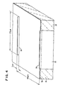
- FIG. 8 shows a fired ceramic 80 material with a cavity 81 into which liquid metal is to be deposited.
- the cavity 81 has a depth of h.
- FIG. 9 shows a set of ceramic sheets 90 and 91 which are stacked in juxtaposition with a film 92 of a metallized ceramic paste with a polymeric material sandwiched between sheets 90 and 91.
- the volatile polymeric material escapes leaving the particles of alumina 93, or the like, behind, holding a space open between sheets 90 and 91 into which the liquid metal can be deposited to form the plates and the tab in hole 59.
Landscapes
- Engineering & Computer Science (AREA)
- Power Engineering (AREA)
- Manufacturing & Machinery (AREA)
- Microelectronics & Electronic Packaging (AREA)
- Fixed Capacitors And Capacitor Manufacturing Machines (AREA)
- Ceramic Capacitors (AREA)
Applications Claiming Priority (2)
| Application Number | Priority Date | Filing Date | Title |
|---|---|---|---|
| US433329 | 1982-10-07 | ||
| US06/433,329 US4430690A (en) | 1982-10-07 | 1982-10-07 | Low inductance MLC capacitor with metal impregnation and solder bar contact |
Publications (3)
| Publication Number | Publication Date |
|---|---|
| EP0108211A2 true EP0108211A2 (de) | 1984-05-16 |
| EP0108211A3 EP0108211A3 (en) | 1984-09-12 |
| EP0108211B1 EP0108211B1 (de) | 1988-06-01 |
Family
ID=23719770
Family Applications (1)
| Application Number | Title | Priority Date | Filing Date |
|---|---|---|---|
| EP83108572A Expired EP0108211B1 (de) | 1982-10-07 | 1983-08-31 | Mehrplattenkondensatoren und Verfahren zu ihrer Herstellung |
Country Status (4)
| Country | Link |
|---|---|
| US (1) | US4430690A (de) |
| EP (1) | EP0108211B1 (de) |
| JP (1) | JPS5969910A (de) |
| DE (1) | DE3376913D1 (de) |
Cited By (2)
| Publication number | Priority date | Publication date | Assignee | Title |
|---|---|---|---|---|
| FR2599546A1 (fr) * | 1986-05-30 | 1987-12-04 | Cimsa Sintra | Condensateur multicouche |
| EP0351343A1 (de) * | 1988-06-27 | 1990-01-17 | International Business Machines Corporation | Mehrschichtkondensator |
Families Citing this family (39)
| Publication number | Priority date | Publication date | Assignee | Title |
|---|---|---|---|---|
| EP0191668B1 (de) * | 1985-01-17 | 1990-03-14 | Eurofarad-Efd | Keramischer Hochfrequenzmehrschichtkondensator mit hoher Kapazität |
| FR2576139B1 (fr) * | 1985-01-17 | 1987-02-20 | Eurofarad | Condensateur ceramique multicouches haute frequence de forte capacite |
| US4705606A (en) * | 1985-01-31 | 1987-11-10 | Gould Inc. | Thin-film electrical connections for integrated circuits |
| US4996584A (en) * | 1985-01-31 | 1991-02-26 | Gould, Inc. | Thin-film electrical connections for integrated circuits |
| US4684446A (en) * | 1985-09-26 | 1987-08-04 | General Electric Company | Secondary metallization by glass displacement in ceramic substrate |
| US4833039A (en) * | 1985-09-26 | 1989-05-23 | General Electric Company | Hermetic feedthrough in ceramic substrate |
| US4732780A (en) * | 1985-09-26 | 1988-03-22 | General Electric Company | Method of making hermetic feedthrough in ceramic substrate |
| DE3771973D1 (de) * | 1986-08-18 | 1991-09-12 | Siemens Ag | Verfahren zur herstellung von fuellschichtbauteilen. |
| US4945399A (en) * | 1986-09-30 | 1990-07-31 | International Business Machines Corporation | Electronic package with integrated distributed decoupling capacitors |
| US4744008A (en) * | 1986-11-18 | 1988-05-10 | International Business Machines Corporation | Flexible film chip carrier with decoupling capacitors |
| US4852227A (en) * | 1988-11-25 | 1989-08-01 | Sprague Electric Company | Method for making a multilayer ceramic capacitor with buried electrodes and terminations at a castellated edge |
| US4862318A (en) * | 1989-04-04 | 1989-08-29 | Avx Corporation | Method of forming thin film terminations of low inductance ceramic capacitors and resultant article |
| US5367430A (en) * | 1992-10-21 | 1994-11-22 | Presidio Components, Inc. | Monolithic multiple capacitor |
| US5375035A (en) * | 1993-03-22 | 1994-12-20 | Compaq Computer Corporation | Capacitor mounting structure for printed circuit boards |
| US5880925A (en) | 1997-06-27 | 1999-03-09 | Avx Corporation | Surface mount multilayer capacitor |
| JP2991175B2 (ja) | 1997-11-10 | 1999-12-20 | 株式会社村田製作所 | 積層コンデンサ |
| US6266229B1 (en) | 1997-11-10 | 2001-07-24 | Murata Manufacturing Co., Ltd | Multilayer capacitor |
| US6266228B1 (en) | 1997-11-10 | 2001-07-24 | Murata Manufacturing Co., Ltd | Multilayer capacitor |
| US6292350B1 (en) | 1997-11-10 | 2001-09-18 | Murata Manufacturing, Co., Ltd | Multilayer capacitor |
| JP3514195B2 (ja) * | 1999-12-27 | 2004-03-31 | 株式会社村田製作所 | 積層コンデンサ、配線基板、デカップリング回路および高周波回路 |
| US6549395B1 (en) | 1997-11-14 | 2003-04-15 | Murata Manufacturing Co., Ltd | Multilayer capacitor |
| US6678927B1 (en) * | 1997-11-24 | 2004-01-20 | Avx Corporation | Miniature surface mount capacitor and method of making same |
| JP3548821B2 (ja) | 1999-05-10 | 2004-07-28 | 株式会社村田製作所 | 積層コンデンサ、ならびにこれを用いた電子装置および高周波回路 |
| JP3476127B2 (ja) | 1999-05-10 | 2003-12-10 | 株式会社村田製作所 | 積層コンデンサ |
| US6327134B1 (en) | 1999-10-18 | 2001-12-04 | Murata Manufacturing Co., Ltd. | Multi-layer capacitor, wiring board, and high-frequency circuit |
| JP3489729B2 (ja) | 1999-11-19 | 2004-01-26 | 株式会社村田製作所 | 積層コンデンサ、配線基板、デカップリング回路および高周波回路 |
| US6477032B2 (en) * | 2001-01-31 | 2002-11-05 | Avx Corporation | Low inductance chip with center via contact |
| US7462942B2 (en) * | 2003-10-09 | 2008-12-09 | Advanpack Solutions Pte Ltd | Die pillar structures and a method of their formation |
| US6951139B2 (en) * | 2003-12-05 | 2005-10-04 | The Goodyear Tire & Rubber Company | Tire sensor and method of assembly |
| US20050133933A1 (en) * | 2003-12-19 | 2005-06-23 | Advanpack Solutions Pte. Ltd. | Various structure/height bumps for wafer level-chip scale package |
| US7408763B2 (en) * | 2005-07-19 | 2008-08-05 | Apurba Roy | Low inductance multilayer capacitor |
| US7645675B2 (en) * | 2006-01-13 | 2010-01-12 | International Business Machines Corporation | Integrated parallel plate capacitors |
| USD689053S1 (en) * | 2011-11-15 | 2013-09-03 | Connectblue Ab | Module |
| USD668658S1 (en) * | 2011-11-15 | 2012-10-09 | Connectblue Ab | Module |
| USD668659S1 (en) * | 2011-11-15 | 2012-10-09 | Connectblue Ab | Module |
| USD680119S1 (en) * | 2011-11-15 | 2013-04-16 | Connectblue Ab | Module |
| USD692896S1 (en) * | 2011-11-15 | 2013-11-05 | Connectblue Ab | Module |
| USD680545S1 (en) * | 2011-11-15 | 2013-04-23 | Connectblue Ab | Module |
| CN115475797B (zh) * | 2022-09-30 | 2024-04-05 | 肇庆绿宝石电子科技股份有限公司 | 一种叠层电容器及其制造方法、载条清洗液及制备方法 |
Citations (2)
| Publication number | Priority date | Publication date | Assignee | Title |
|---|---|---|---|---|
| US3778532A (en) * | 1972-07-03 | 1973-12-11 | Illinois Tool Works | Electrical circuit component having solder preform connection means |
| EP0042987B1 (de) * | 1980-06-30 | 1989-03-08 | International Business Machines Corporation | Träger mit elektronischer Schaltung für Halbleiteranordnung |
Family Cites Families (10)
| Publication number | Priority date | Publication date | Assignee | Title |
|---|---|---|---|---|
| US3235939A (en) | 1962-09-06 | 1966-02-22 | Aerovox Corp | Process for manufacturing multilayer ceramic capacitors |
| US3852877A (en) | 1969-08-06 | 1974-12-10 | Ibm | Multilayer circuits |
| US3679950A (en) | 1971-04-16 | 1972-07-25 | Nl Industries Inc | Ceramic capacitors |
| US4030004A (en) | 1971-04-16 | 1977-06-14 | Nl Industries, Inc. | Dielectric ceramic matrices with end barriers |
| US3965552A (en) | 1972-07-24 | 1976-06-29 | N L Industries, Inc. | Process for forming internal conductors and electrodes |
| US3784887A (en) | 1973-04-26 | 1974-01-08 | Du Pont | Process for making capacitors and capacitors made thereby |
| US4189760A (en) | 1973-05-13 | 1980-02-19 | Erie Technological Products, Inc. | Monolithic capacitor with non-noble metal electrodes and method of making the same |
| US3879645A (en) | 1973-09-24 | 1975-04-22 | Nl Industries Inc | Ceramic capacitors |
| US4246625A (en) | 1978-11-16 | 1981-01-20 | Union Carbide Corporation | Ceramic capacitor with co-fired end terminations |
| US4297773A (en) | 1978-11-16 | 1981-11-03 | Avx Corporation | Method of manufacturing a monolithic ceramic capacitor |
-
1982
- 1982-10-07 US US06/433,329 patent/US4430690A/en not_active Expired - Lifetime
-
1983
- 1983-06-20 JP JP58109440A patent/JPS5969910A/ja active Granted
- 1983-08-31 EP EP83108572A patent/EP0108211B1/de not_active Expired
- 1983-08-31 DE DE8383108572T patent/DE3376913D1/de not_active Expired
Patent Citations (2)
| Publication number | Priority date | Publication date | Assignee | Title |
|---|---|---|---|---|
| US3778532A (en) * | 1972-07-03 | 1973-12-11 | Illinois Tool Works | Electrical circuit component having solder preform connection means |
| EP0042987B1 (de) * | 1980-06-30 | 1989-03-08 | International Business Machines Corporation | Träger mit elektronischer Schaltung für Halbleiteranordnung |
Non-Patent Citations (1)
| Title |
|---|
| IBM TECHNICAL DISCLOSURE BULLETIN, vol. 24, no. 11B, April 1982, pages 5294-5295, New York, US * |
Cited By (3)
| Publication number | Priority date | Publication date | Assignee | Title |
|---|---|---|---|---|
| FR2599546A1 (fr) * | 1986-05-30 | 1987-12-04 | Cimsa Sintra | Condensateur multicouche |
| EP0251831A1 (de) * | 1986-05-30 | 1988-01-07 | Cimsa Sintra | Mehrschichtkondensator |
| EP0351343A1 (de) * | 1988-06-27 | 1990-01-17 | International Business Machines Corporation | Mehrschichtkondensator |
Also Published As
| Publication number | Publication date |
|---|---|
| EP0108211B1 (de) | 1988-06-01 |
| EP0108211A3 (en) | 1984-09-12 |
| US4430690A (en) | 1984-02-07 |
| DE3376913D1 (en) | 1988-07-07 |
| JPH0218573B2 (de) | 1990-04-26 |
| JPS5969910A (ja) | 1984-04-20 |
Similar Documents
| Publication | Publication Date | Title |
|---|---|---|
| EP0108211B1 (de) | Mehrplattenkondensatoren und Verfahren zu ihrer Herstellung | |
| US5329695A (en) | Method of manufacturing a multilayer circuit board | |
| EP0100175B1 (de) | Chip-Kondensator mit biegsamem Anschluss | |
| US4712161A (en) | Hybrid and multi-layer circuitry | |
| US5309629A (en) | Method of manufacturing a multilayer circuit board | |
| EP0249755B1 (de) | Integrierte Hybridschaltung | |
| US4879156A (en) | Multilayered ceramic substrate having solid non-porous metal conductors | |
| EP0244696A2 (de) | Verfahren zum Herstellen eines keramischen Mehrshictsubstrates mit massivem nicht-porösem Metall-Leiter | |
| US4696851A (en) | Hybrid and multi-layer circuitry | |
| KR20040031680A (ko) | 전자 장치 및 그 제조 방법 | |
| EP0163172A2 (de) | Verfahren zum Erzeugen eines Metallisierungsmusters auf der Oberfläche eines Keramiksubstrats | |
| US6242075B1 (en) | Planar multilayer ceramic structures with near surface channels | |
| US5302219A (en) | Method for obtaining via patterns in ceramic sheets | |
| JP3003413B2 (ja) | 多層セラミック基板の製造方法 | |
| JPH10335823A (ja) | 積層セラミック回路基板及びその製造方法 | |
| JPH0817965A (ja) | 電子コンポーネントおよびその製造方法 | |
| EP0193907A2 (de) | Hybrid- und Mehrschichtschaltung | |
| JP2007067364A (ja) | チップ型電子部品を搭載したセラミック基板及びその製造方法 | |
| JP4646417B2 (ja) | セラミック回路基板 | |
| US6846375B2 (en) | Method of manufacturing multilayer ceramic wiring board and conductive paste for use | |
| JPH06164143A (ja) | 多層ハイブリッド回路の製造方法 | |
| US4461077A (en) | Method for preparing ceramic articles having raised, selectively metallized electrical contact points | |
| JPH0521635A (ja) | 多層基板 | |
| JP4493158B2 (ja) | セラミック回路基板 | |
| JPS63239999A (ja) | セラミツク多層積層体の製造方法 |
Legal Events
| Date | Code | Title | Description |
|---|---|---|---|
| PUAI | Public reference made under article 153(3) epc to a published international application that has entered the european phase |
Free format text: ORIGINAL CODE: 0009012 |
|
| AK | Designated contracting states |
Designated state(s): DE FR GB |
|
| PUAL | Search report despatched |
Free format text: ORIGINAL CODE: 0009013 |
|
| AK | Designated contracting states |
Designated state(s): DE FR GB |
|
| 17P | Request for examination filed |
Effective date: 19840823 |
|
| GRAA | (expected) grant |
Free format text: ORIGINAL CODE: 0009210 |
|
| AK | Designated contracting states |
Kind code of ref document: B1 Designated state(s): DE FR GB |
|
| REF | Corresponds to: |
Ref document number: 3376913 Country of ref document: DE Date of ref document: 19880707 |
|
| ET | Fr: translation filed | ||
| PLBE | No opposition filed within time limit |
Free format text: ORIGINAL CODE: 0009261 |
|
| STAA | Information on the status of an ep patent application or granted ep patent |
Free format text: STATUS: NO OPPOSITION FILED WITHIN TIME LIMIT |
|
| 26N | No opposition filed | ||
| PGFP | Annual fee paid to national office [announced via postgrant information from national office to epo] |
Ref country code: DE Payment date: 19930824 Year of fee payment: 11 |
|
| PGFP | Annual fee paid to national office [announced via postgrant information from national office to epo] |
Ref country code: FR Payment date: 19940725 Year of fee payment: 12 |
|
| PGFP | Annual fee paid to national office [announced via postgrant information from national office to epo] |
Ref country code: GB Payment date: 19940726 Year of fee payment: 12 |
|
| PG25 | Lapsed in a contracting state [announced via postgrant information from national office to epo] |
Ref country code: DE Effective date: 19950503 |
|
| PG25 | Lapsed in a contracting state [announced via postgrant information from national office to epo] |
Ref country code: GB Effective date: 19950831 |
|
| PG25 | Lapsed in a contracting state [announced via postgrant information from national office to epo] |
Ref country code: FR Effective date: 19960430 |
|
| GBPC | Gb: european patent ceased through non-payment of renewal fee |
Effective date: 19950831 |
|
| REG | Reference to a national code |
Ref country code: FR Ref legal event code: ST |