EP0107005A1 - Bride de fixation pour outils, en particulier pour outils de travail du sol - Google Patents
Bride de fixation pour outils, en particulier pour outils de travail du sol Download PDFInfo
- Publication number
- EP0107005A1 EP0107005A1 EP83109011A EP83109011A EP0107005A1 EP 0107005 A1 EP0107005 A1 EP 0107005A1 EP 83109011 A EP83109011 A EP 83109011A EP 83109011 A EP83109011 A EP 83109011A EP 0107005 A1 EP0107005 A1 EP 0107005A1
- Authority
- EP
- European Patent Office
- Prior art keywords
- leg
- carrier
- holder
- web
- end part
- Prior art date
- Legal status (The legal status is an assumption and is not a legal conclusion. Google has not performed a legal analysis and makes no representation as to the accuracy of the status listed.)
- Ceased
Links
Images
Classifications
-
- A—HUMAN NECESSITIES
- A01—AGRICULTURE; FORESTRY; ANIMAL HUSBANDRY; HUNTING; TRAPPING; FISHING
- A01B—SOIL WORKING IN AGRICULTURE OR FORESTRY; PARTS, DETAILS, OR ACCESSORIES OF AGRICULTURAL MACHINES OR IMPLEMENTS, IN GENERAL
- A01B23/00—Elements, tools, or details of harrows
- A01B23/02—Teeth; Fixing the teeth
-
- Y—GENERAL TAGGING OF NEW TECHNOLOGICAL DEVELOPMENTS; GENERAL TAGGING OF CROSS-SECTIONAL TECHNOLOGIES SPANNING OVER SEVERAL SECTIONS OF THE IPC; TECHNICAL SUBJECTS COVERED BY FORMER USPC CROSS-REFERENCE ART COLLECTIONS [XRACs] AND DIGESTS
- Y10—TECHNICAL SUBJECTS COVERED BY FORMER USPC
- Y10T—TECHNICAL SUBJECTS COVERED BY FORMER US CLASSIFICATION
- Y10T403/00—Joints and connections
- Y10T403/71—Rod side to plate or side
- Y10T403/7164—One rod held between bight and other rod extending through aperture in leg of connector
-
- Y—GENERAL TAGGING OF NEW TECHNOLOGICAL DEVELOPMENTS; GENERAL TAGGING OF CROSS-SECTIONAL TECHNOLOGIES SPANNING OVER SEVERAL SECTIONS OF THE IPC; TECHNICAL SUBJECTS COVERED BY FORMER USPC CROSS-REFERENCE ART COLLECTIONS [XRACs] AND DIGESTS
- Y10—TECHNICAL SUBJECTS COVERED BY FORMER USPC
- Y10T—TECHNICAL SUBJECTS COVERED BY FORMER US CLASSIFICATION
- Y10T403/00—Joints and connections
- Y10T403/71—Rod side to plate or side
- Y10T403/7171—Two rods encompassed by single connector
-
- Y—GENERAL TAGGING OF NEW TECHNOLOGICAL DEVELOPMENTS; GENERAL TAGGING OF CROSS-SECTIONAL TECHNOLOGIES SPANNING OVER SEVERAL SECTIONS OF THE IPC; TECHNICAL SUBJECTS COVERED BY FORMER USPC CROSS-REFERENCE ART COLLECTIONS [XRACs] AND DIGESTS
- Y10—TECHNICAL SUBJECTS COVERED BY FORMER USPC
- Y10T—TECHNICAL SUBJECTS COVERED BY FORMER US CLASSIFICATION
- Y10T403/00—Joints and connections
- Y10T403/71—Rod side to plate or side
- Y10T403/7194—Crossed rods
Definitions
- the invention relates to a holder for fastening a working tool, in particular for fastening a working tool of a soil cultivation implement, the holder consisting of two approximately rectangular legs which can be brought into contact with the surface of a carrier formed from at least two side parts and with each are provided with a penetration, the one penetration for receiving a web of the working tool and the other penetration for receiving a fastening bolt which presses the holder against the surfaces of the carrier.
- a holder for fastening a tillage tool with a share tip is generally known, the holder being formed from two mutually rectangular legs, which bear against the back and the top of a box-shaped carrier.
- the work tool has a horizontally extending web which bears against the underside of the carrier and can be fastened by means of a screw bolt which extends for this purpose through a bore in the horizontally extending leg.
- the invention has for its object to design and arrange the holder for fastening a work tool such that even with excessive tightening of a screw bolt for fastening the holder there is no permanent deformation on the holder and that after prolonged use of the work tool there is no automatic loosening of the screw bolt can.
- the one leg for receiving the fastening bolt is provided with a shaped piece or web which has a depression pointing in the direction of the web of the working tool, the web being connected to the leg via an at least partially curved part, which can be placed against a corner part of the carrier formed from at least two side parts and partially surrounds it.
- the advantageous design and arrangement of the holder with the associated fitting, which gradually merges into one leg of the holder via the curved part, results in a relatively resistant part for receiving the screw bolt, which is not subject to permanent deformation even when the screw bolt is excessively tightened, so that a perfect securing of the tillage tool on the carrier is always guaranteed.
- the curved part enables the holder to be clamped onto the carrier from above, so that no movement of the holder relative to the carrier is possible, even when the screw bolt has loosened a little. Since there is no permanent deformation of the molded part due to the advantageous design of the molded part, the serve by tightening the Bending forces caused by the bolt to self-secure the nut or bolt. This enables a chatter-free connection of the holder to the carrier.
- the web of one leg which is designed as an end part, has an approximately V-shaped indentation or depression which points in the direction of the corner part or in the direction of the longitudinal axis of the fastening bolt.
- a shaped piece can be produced relatively easily and also enables the curved part to be formed between the end part and the one horizontally extending leg of the holder.
- the contact surface of the first leg lying against the carrier runs flat and the end part has approximately the same width as the first leg.
- the end part has curved side parts which can be brought into abutment against the corner part of the carrier.
- the carrier has an approximately rectangular cross section, against the upper corner part of which the arcuate end part can be pressed.
- the one leg rests with the end part against the top of the carrier and the web against the underside of the carrier, while the leg extending rectangularly to the first leg lies against the vertically running back of the carrier and the corner part is provided opposite the back is.
- the end part from an extension formed of the leg center piece with two downwardly bent side parts, which gradually merge into the horizontal part of the leg and are adapted to the corner part of the carrier, and that the angle between the legs is 90 ° or slightly less than 90 °.
- the two legs are slightly pushed apart by tightening the screw bolt and pressed flat into their end position against the surface of the carrier, so that a rattle-free connection between the holder and the carrier is created can.
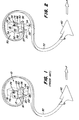
- 32 denotes an S-shaped prong in FIG. 2, which is connected to a carrier 22 by means of a fastening device at a point denoted by 50.
- the necessary holder 52 of the fastening device consists of a first and second leg 54 and 56 with flat flange parts 55 and 57, which are on the top 18 and the back 20 of the carrier 22 rest.
- the leg 54 of the holder 52 has a web or a protruding part or end part 58 which is equipped with downwardly angled side parts 62 which, with the center piece of the web 58, result in an approximately inverted V-shaped profile.
- the web 58 is provided in the center with a bore or slot opening 64 (see FIGS.
- the bore or the slot opening 64 extends in the direction of the web 34.
- the side parts 62 are connected to the flange part 55 of the leg 54.
- the downwardly angled side parts 62 gradually merge into the flange part 55.
- the transition point between the side parts 62 and the flange part 55 is denoted by 66, which is adapted to the upper corner part, which is formed by the upper side 18 and a front side 28 of the carrier 22.
- the transition point or the arcuate part 66 is designed so that it can be clamped onto the carrier 22 in connection with the flange part 57.
- the fastening bolt 40 is tightened and pulls the web 58 and the flange part 57 downward against the surface of the upper side 18 of the carrier 22.
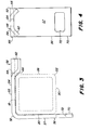
- the web 58 can be manufactured, for example, in a die and thus obtain the desired depression or cross section (see FIG. 4).
- the bending strength of the flat metal for the holder 52 can be increased with a certain width and thickness.
- the leg 56 is provided with a lower edge 70, in the area of which a penetration or slot opening 72 is provided, which serves to receive a horizontally extending web 34 of the tine 32.
- the web 34 runs below an underside 30 of the carrier 22.
- the fastening bolt 40 is inserted into a corresponding bore provided in the web 34 or in the region of its end 36 ten introduced and then passed through the bore 64 in the web 58.
- the fastening bolt 40 can be secured with a nut 76, which for this purpose is screwed onto the fastening bolt 40 from above and can thereby be brought into abutment against the surface of the web 58.
- the shaped web 58 with its curved shaped part 66 is pressed firmly against the upper corner part of the carrier 22, the web 34 being pressed against the underside 30 of the carrier 22 from below.
- the legs 54 and 56 are aligned approximately at right angles to one another, it being possible for the angle (see FIG. 3) to be somewhat less than 90 °. This prevents rattling of the lower edge or the lower end 70 and the remaining part of the leg 56 when the fastening bolt 40 is tightened. It also prevents the leg 56 from striking the rear side 20 of the carrier 22, since the fastening bolt 40 pulls the holder 52 and the associated corner part forwards and downwards, this movement of the holder being supported by the curved molded part 66 which is supported by Tightening the fastening bolt 40 ensures that the leg 56 is pressed almost completely flat against the back 20 and the leg 54 against the top 18 of the carrier 22.
Applications Claiming Priority (2)
| Application Number | Priority Date | Filing Date | Title |
|---|---|---|---|
| US06/425,778 US4465396A (en) | 1982-09-28 | 1982-09-28 | Shank clamp |
| US425778 | 1982-09-28 |
Publications (1)
| Publication Number | Publication Date |
|---|---|
| EP0107005A1 true EP0107005A1 (fr) | 1984-05-02 |
Family
ID=23687995
Family Applications (1)
| Application Number | Title | Priority Date | Filing Date |
|---|---|---|---|
| EP83109011A Ceased EP0107005A1 (fr) | 1982-09-28 | 1983-09-13 | Bride de fixation pour outils, en particulier pour outils de travail du sol |
Country Status (7)
| Country | Link |
|---|---|
| US (1) | US4465396A (fr) |
| EP (1) | EP0107005A1 (fr) |
| AU (1) | AU555700B2 (fr) |
| CA (1) | CA1212568A (fr) |
| DK (1) | DK444483A (fr) |
| ES (1) | ES282332Y (fr) |
| ZA (1) | ZA837154B (fr) |
Cited By (1)
| Publication number | Priority date | Publication date | Assignee | Title |
|---|---|---|---|---|
| EP2451263A1 (fr) * | 2009-07-09 | 2012-05-16 | Väderstad-Verken AB | Montage d'un outil sur une machine agricole |
Families Citing this family (6)
| Publication number | Priority date | Publication date | Assignee | Title |
|---|---|---|---|---|
| US5335735A (en) * | 1990-10-24 | 1994-08-09 | Kent Manufacturing Co., Inc. | Cultivator shank assembly with cammed shank end receiver |
| US5133415A (en) * | 1990-10-24 | 1992-07-28 | Kent Manufacturing Co., Inc. | Cultivator shank assembly |
| DK173276B1 (da) * | 1998-02-05 | 2000-06-05 | Kongskilde Ind As | Spændestykke, fremgangsmåde til fremstilling af spændestykke, samt landbrugsmaskine, der anvender spændestykket |
| SE0500263L (sv) * | 2005-02-02 | 2005-11-08 | Vaederstad Verken Ab | Anordning vid en fjäderpinne eller liknande för en lantbruksmaskin |
| US9504197B2 (en) | 2013-09-03 | 2016-11-29 | Cnh Industrial America Llc | Disc blade clamping device |
| US20220132719A1 (en) * | 2020-10-30 | 2022-05-05 | Honey Bee Manufacturing Ltd. | Agricultural implement with tine assembly |
Citations (3)
| Publication number | Priority date | Publication date | Assignee | Title |
|---|---|---|---|---|
| US3827505A (en) * | 1972-08-04 | 1974-08-06 | Royal Industries | Mounting clamp for spring tooth |
| FR2310687A1 (fr) * | 1975-05-16 | 1976-12-10 | Anjou Atel Mec | Bride pour le montage d'une dent sur le chassis, notamment pour un instrument de preparation du sol avant semis |
| FR2507709A1 (fr) * | 1981-06-16 | 1982-12-17 | Kongskilde Koncernselskab As | Ferrure angulaire a boulon de serrage de deux elements en forme de barre qui se croisent l'un l'autre, en particulier serrage d'une dent de herse sur une barre de support |
Family Cites Families (3)
| Publication number | Priority date | Publication date | Assignee | Title |
|---|---|---|---|---|
| US1394904A (en) * | 1920-07-09 | 1921-10-25 | Badger Mfg Corp | Clamp |
| US3896883A (en) * | 1973-01-12 | 1975-07-29 | Varlen Corp | Cultivator tooth assembly |
| US4050524A (en) * | 1976-05-17 | 1977-09-27 | Kent Manufacturing Co., Inc. | Cultivator tooth clamp |
-
1982
- 1982-09-28 US US06/425,778 patent/US4465396A/en not_active Expired - Lifetime
-
1983
- 1983-08-23 AU AU18321/83A patent/AU555700B2/en not_active Ceased
- 1983-08-24 CA CA000435296A patent/CA1212568A/fr not_active Expired
- 1983-09-13 EP EP83109011A patent/EP0107005A1/fr not_active Ceased
- 1983-09-26 ZA ZA837154A patent/ZA837154B/xx unknown
- 1983-09-27 ES ES1983282332U patent/ES282332Y/es not_active Expired
- 1983-09-28 DK DK444483A patent/DK444483A/da not_active Application Discontinuation
Patent Citations (3)
| Publication number | Priority date | Publication date | Assignee | Title |
|---|---|---|---|---|
| US3827505A (en) * | 1972-08-04 | 1974-08-06 | Royal Industries | Mounting clamp for spring tooth |
| FR2310687A1 (fr) * | 1975-05-16 | 1976-12-10 | Anjou Atel Mec | Bride pour le montage d'une dent sur le chassis, notamment pour un instrument de preparation du sol avant semis |
| FR2507709A1 (fr) * | 1981-06-16 | 1982-12-17 | Kongskilde Koncernselskab As | Ferrure angulaire a boulon de serrage de deux elements en forme de barre qui se croisent l'un l'autre, en particulier serrage d'une dent de herse sur une barre de support |
Non-Patent Citations (1)
| Title |
|---|
| BRÜNEN UND CO., "Federzinken für Kultureggen", Brochüre, DLG. München, 19-26 Mai 1968 * |
Cited By (2)
| Publication number | Priority date | Publication date | Assignee | Title |
|---|---|---|---|---|
| EP2451263A1 (fr) * | 2009-07-09 | 2012-05-16 | Väderstad-Verken AB | Montage d'un outil sur une machine agricole |
| EP2451263A4 (fr) * | 2009-07-09 | 2012-12-05 | Vaederstad Verken Ab | Montage d'un outil sur une machine agricole |
Also Published As
| Publication number | Publication date |
|---|---|
| DK444483D0 (da) | 1983-09-28 |
| CA1212568A (fr) | 1986-10-14 |
| DK444483A (da) | 1984-03-29 |
| AU1832183A (en) | 1984-04-05 |
| ES282332Y (es) | 1985-12-16 |
| ZA837154B (en) | 1985-05-29 |
| ES282332U (es) | 1985-05-01 |
| US4465396A (en) | 1984-08-14 |
| AU555700B2 (en) | 1986-10-02 |
Similar Documents
| Publication | Publication Date | Title |
|---|---|---|
| DE3744176C2 (fr) | ||
| DE7532429U (de) | Aufhaengevorrichtung, insbesondere fuer eine decke oder teile derselben | |
| DE3936243C2 (de) | Verstellbarer Anschlag für eine Wendeschneidplatte | |
| DE3152006A1 (de) | Schneidewerkzeug fuer metall mit auswechselbaren schneideinsaetzen | |
| EP0389604A1 (fr) | Dispositif de serrage | |
| CH659613A5 (de) | Befestigungskloben. | |
| DE4222494C2 (de) | Dachträger für Fahrzeuge | |
| EP0107005A1 (fr) | Bride de fixation pour outils, en particulier pour outils de travail du sol | |
| WO2008098744A1 (fr) | Outil de mortaisage, en particulier pour la réalisation de rainures | |
| EP0479818B1 (fr) | Butee parallele et angulaire | |
| WO2014027047A1 (fr) | Dispositif adaptateur pour tiroir | |
| EP0010260B1 (fr) | Serre-joints | |
| DE2225747C2 (de) | Schneidwerkzeug für die spanabhebende Bearbeitung | |
| DE60214242T2 (de) | Struktur für das Halten eines Karosserieteiles | |
| DE3135881C1 (de) | Spannzwinge | |
| DE3204354C2 (de) | Winkelbeschlag zum Festspannen einer Eggenzinke | |
| DE4137618C2 (fr) | ||
| DE102005027818B4 (de) | Haltegriff mit universell verwendbarer Messerklinge | |
| DE3500423A1 (de) | Scharnier, insbesondere fuer moebel | |
| DE6800555U (de) | Verschliessbarer behaelter zur aufnahme von werkzeugen, der batterie od. dgl. | |
| DE202004012350U1 (de) | Verbindungsbeschlag für Platten, insbesondere für Tablare | |
| EP0118077A2 (fr) | Butée à onglets | |
| EP0809748B1 (fr) | Porte-outil pour haveuses | |
| DE2928871C2 (fr) | ||
| DE2644336C2 (de) | Tragvorrichtung für Möbelbauteile |
Legal Events
| Date | Code | Title | Description |
|---|---|---|---|
| PUAI | Public reference made under article 153(3) epc to a published international application that has entered the european phase |
Free format text: ORIGINAL CODE: 0009012 |
|
| AK | Designated contracting states |
Designated state(s): AT DE FR GB |
|
| EL | Fr: translation of claims filed | ||
| 17P | Request for examination filed |
Effective date: 19841026 |
|
| STAA | Information on the status of an ep patent application or granted ep patent |
Free format text: STATUS: THE APPLICATION HAS BEEN REFUSED |
|
| 18R | Application refused |
Effective date: 19871123 |
|
| RIN1 | Information on inventor provided before grant (corrected) |
Inventor name: SUNDBERG, JOHN DAVID Inventor name: MEINERT, HARRY MATHAIS |