EP0107005A1 - Mounting clamp for tools, especially for ground-working tools - Google Patents
Mounting clamp for tools, especially for ground-working tools Download PDFInfo
- Publication number
- EP0107005A1 EP0107005A1 EP83109011A EP83109011A EP0107005A1 EP 0107005 A1 EP0107005 A1 EP 0107005A1 EP 83109011 A EP83109011 A EP 83109011A EP 83109011 A EP83109011 A EP 83109011A EP 0107005 A1 EP0107005 A1 EP 0107005A1
- Authority
- EP
- European Patent Office
- Prior art keywords
- leg
- carrier
- holder
- web
- end part
- Prior art date
- Legal status (The legal status is an assumption and is not a legal conclusion. Google has not performed a legal analysis and makes no representation as to the accuracy of the status listed.)
- Ceased
Links
Images
Classifications
-
- A—HUMAN NECESSITIES
- A01—AGRICULTURE; FORESTRY; ANIMAL HUSBANDRY; HUNTING; TRAPPING; FISHING
- A01B—SOIL WORKING IN AGRICULTURE OR FORESTRY; PARTS, DETAILS, OR ACCESSORIES OF AGRICULTURAL MACHINES OR IMPLEMENTS, IN GENERAL
- A01B23/00—Elements, tools, or details of harrows
- A01B23/02—Teeth; Fixing the teeth
-
- Y—GENERAL TAGGING OF NEW TECHNOLOGICAL DEVELOPMENTS; GENERAL TAGGING OF CROSS-SECTIONAL TECHNOLOGIES SPANNING OVER SEVERAL SECTIONS OF THE IPC; TECHNICAL SUBJECTS COVERED BY FORMER USPC CROSS-REFERENCE ART COLLECTIONS [XRACs] AND DIGESTS
- Y10—TECHNICAL SUBJECTS COVERED BY FORMER USPC
- Y10T—TECHNICAL SUBJECTS COVERED BY FORMER US CLASSIFICATION
- Y10T403/00—Joints and connections
- Y10T403/71—Rod side to plate or side
- Y10T403/7164—One rod held between bight and other rod extending through aperture in leg of connector
-
- Y—GENERAL TAGGING OF NEW TECHNOLOGICAL DEVELOPMENTS; GENERAL TAGGING OF CROSS-SECTIONAL TECHNOLOGIES SPANNING OVER SEVERAL SECTIONS OF THE IPC; TECHNICAL SUBJECTS COVERED BY FORMER USPC CROSS-REFERENCE ART COLLECTIONS [XRACs] AND DIGESTS
- Y10—TECHNICAL SUBJECTS COVERED BY FORMER USPC
- Y10T—TECHNICAL SUBJECTS COVERED BY FORMER US CLASSIFICATION
- Y10T403/00—Joints and connections
- Y10T403/71—Rod side to plate or side
- Y10T403/7171—Two rods encompassed by single connector
-
- Y—GENERAL TAGGING OF NEW TECHNOLOGICAL DEVELOPMENTS; GENERAL TAGGING OF CROSS-SECTIONAL TECHNOLOGIES SPANNING OVER SEVERAL SECTIONS OF THE IPC; TECHNICAL SUBJECTS COVERED BY FORMER USPC CROSS-REFERENCE ART COLLECTIONS [XRACs] AND DIGESTS
- Y10—TECHNICAL SUBJECTS COVERED BY FORMER USPC
- Y10T—TECHNICAL SUBJECTS COVERED BY FORMER US CLASSIFICATION
- Y10T403/00—Joints and connections
- Y10T403/71—Rod side to plate or side
- Y10T403/7194—Crossed rods
Definitions
- the invention relates to a holder for fastening a working tool, in particular for fastening a working tool of a soil cultivation implement, the holder consisting of two approximately rectangular legs which can be brought into contact with the surface of a carrier formed from at least two side parts and with each are provided with a penetration, the one penetration for receiving a web of the working tool and the other penetration for receiving a fastening bolt which presses the holder against the surfaces of the carrier.
- a holder for fastening a tillage tool with a share tip is generally known, the holder being formed from two mutually rectangular legs, which bear against the back and the top of a box-shaped carrier.
- the work tool has a horizontally extending web which bears against the underside of the carrier and can be fastened by means of a screw bolt which extends for this purpose through a bore in the horizontally extending leg.
- the invention has for its object to design and arrange the holder for fastening a work tool such that even with excessive tightening of a screw bolt for fastening the holder there is no permanent deformation on the holder and that after prolonged use of the work tool there is no automatic loosening of the screw bolt can.
- the one leg for receiving the fastening bolt is provided with a shaped piece or web which has a depression pointing in the direction of the web of the working tool, the web being connected to the leg via an at least partially curved part, which can be placed against a corner part of the carrier formed from at least two side parts and partially surrounds it.
- the advantageous design and arrangement of the holder with the associated fitting, which gradually merges into one leg of the holder via the curved part, results in a relatively resistant part for receiving the screw bolt, which is not subject to permanent deformation even when the screw bolt is excessively tightened, so that a perfect securing of the tillage tool on the carrier is always guaranteed.
- the curved part enables the holder to be clamped onto the carrier from above, so that no movement of the holder relative to the carrier is possible, even when the screw bolt has loosened a little. Since there is no permanent deformation of the molded part due to the advantageous design of the molded part, the serve by tightening the Bending forces caused by the bolt to self-secure the nut or bolt. This enables a chatter-free connection of the holder to the carrier.
- the web of one leg which is designed as an end part, has an approximately V-shaped indentation or depression which points in the direction of the corner part or in the direction of the longitudinal axis of the fastening bolt.
- a shaped piece can be produced relatively easily and also enables the curved part to be formed between the end part and the one horizontally extending leg of the holder.
- the contact surface of the first leg lying against the carrier runs flat and the end part has approximately the same width as the first leg.
- the end part has curved side parts which can be brought into abutment against the corner part of the carrier.
- the carrier has an approximately rectangular cross section, against the upper corner part of which the arcuate end part can be pressed.
- the one leg rests with the end part against the top of the carrier and the web against the underside of the carrier, while the leg extending rectangularly to the first leg lies against the vertically running back of the carrier and the corner part is provided opposite the back is.
- the end part from an extension formed of the leg center piece with two downwardly bent side parts, which gradually merge into the horizontal part of the leg and are adapted to the corner part of the carrier, and that the angle between the legs is 90 ° or slightly less than 90 °.
- the two legs are slightly pushed apart by tightening the screw bolt and pressed flat into their end position against the surface of the carrier, so that a rattle-free connection between the holder and the carrier is created can.
- 32 denotes an S-shaped prong in FIG. 2, which is connected to a carrier 22 by means of a fastening device at a point denoted by 50.
- the necessary holder 52 of the fastening device consists of a first and second leg 54 and 56 with flat flange parts 55 and 57, which are on the top 18 and the back 20 of the carrier 22 rest.
- the leg 54 of the holder 52 has a web or a protruding part or end part 58 which is equipped with downwardly angled side parts 62 which, with the center piece of the web 58, result in an approximately inverted V-shaped profile.
- the web 58 is provided in the center with a bore or slot opening 64 (see FIGS.
- the bore or the slot opening 64 extends in the direction of the web 34.
- the side parts 62 are connected to the flange part 55 of the leg 54.
- the downwardly angled side parts 62 gradually merge into the flange part 55.
- the transition point between the side parts 62 and the flange part 55 is denoted by 66, which is adapted to the upper corner part, which is formed by the upper side 18 and a front side 28 of the carrier 22.
- the transition point or the arcuate part 66 is designed so that it can be clamped onto the carrier 22 in connection with the flange part 57.
- the fastening bolt 40 is tightened and pulls the web 58 and the flange part 57 downward against the surface of the upper side 18 of the carrier 22.
- the web 58 can be manufactured, for example, in a die and thus obtain the desired depression or cross section (see FIG. 4).
- the bending strength of the flat metal for the holder 52 can be increased with a certain width and thickness.
- the leg 56 is provided with a lower edge 70, in the area of which a penetration or slot opening 72 is provided, which serves to receive a horizontally extending web 34 of the tine 32.
- the web 34 runs below an underside 30 of the carrier 22.
- the fastening bolt 40 is inserted into a corresponding bore provided in the web 34 or in the region of its end 36 ten introduced and then passed through the bore 64 in the web 58.
- the fastening bolt 40 can be secured with a nut 76, which for this purpose is screwed onto the fastening bolt 40 from above and can thereby be brought into abutment against the surface of the web 58.
- the shaped web 58 with its curved shaped part 66 is pressed firmly against the upper corner part of the carrier 22, the web 34 being pressed against the underside 30 of the carrier 22 from below.
- the legs 54 and 56 are aligned approximately at right angles to one another, it being possible for the angle (see FIG. 3) to be somewhat less than 90 °. This prevents rattling of the lower edge or the lower end 70 and the remaining part of the leg 56 when the fastening bolt 40 is tightened. It also prevents the leg 56 from striking the rear side 20 of the carrier 22, since the fastening bolt 40 pulls the holder 52 and the associated corner part forwards and downwards, this movement of the holder being supported by the curved molded part 66 which is supported by Tightening the fastening bolt 40 ensures that the leg 56 is pressed almost completely flat against the back 20 and the leg 54 against the top 18 of the carrier 22.
Abstract
Eine Halterung (52) zur Befestigung einer Zinke (32) eines Bodenbearbeitungswerkzeuges ist an einen rechteckförmigen Kastenträger (22) mittels eines Befestigungsbolzens (40) lösbar angeschlossen. Die Halterung (52) besteht aus zwei rechteckförmig zueinander verlaufenden Schenkeln (54, 56). Der eine Schenkel (54) weist ein in etwa V-förmiges Formteil bzw. Endteil (58) auf. Das Endteil (58) besteht aus einem Mittelstück mit zwei nach unten abgewinkelten Seitenteilen (62), die allmählich in den flachen Teil des Schenkels (54) übergehen und dabei dem einen Eckteil des Trägers (22) angepaßt sind, damit nach Anziehen des Befestigungsbolzens (40) die Halterung ratterfrei auf den Träger aufbringbar bzw. festklemmbar ist.A holder (52) for fastening a tine (32) of a soil cultivation tool is detachably connected to a rectangular box girder (22) by means of a fastening bolt (40). The holder (52) consists of two mutually rectangular legs (54, 56). One leg (54) has an approximately V-shaped molded part or end part (58). The end part (58) consists of a center piece with two downwardly angled side parts (62), which gradually merge into the flat part of the leg (54) and are adapted to one corner part of the support (22) so that after tightening the fastening bolt ( 40) the holder can be rattle-free or clamped onto the carrier.
Description
Die Erfindung bezieht sich auf eine Halterung zur Befestigung eines Arbeitswerkzeuges, insbesondere zur Befestigung eines Arbeitswerkzeuges eines Bodenbearbeitungsgerätes, wobei die Halterung aus zwei in etwa rechteckförmig zueinander verlaufenden Schenkeln besteht, die gegen die Oberfläche eines aus zumindest zwei Seitenteilen gebildeten Trägers zur Anlage bringbar und mit je einer Durchdringung versehen sind, wobei die eine Durchdringung zur Aufnahme eines Steges des Arbeitswerkzeuges und die andere Durchdringung zur Aufnahme eines Befestigungsbolzens dient, der die Halterung gegen die Oberflächen des Trägers drückt.The invention relates to a holder for fastening a working tool, in particular for fastening a working tool of a soil cultivation implement, the holder consisting of two approximately rectangular legs which can be brought into contact with the surface of a carrier formed from at least two side parts and with each are provided with a penetration, the one penetration for receiving a web of the working tool and the other penetration for receiving a fastening bolt which presses the holder against the surfaces of the carrier.
Es ist eine Halterung zur Befestigung eines Bodenbearbeitungswerkzeuges mit einer Scharspitze allgemein bekannt, wobei die Halterung aus zwei rechteckförmig zueinander verlaufenden Schenkeln gebildet ist, die gegen die Rückseite und die Oberseite eines kastenförmigen Trägers anliegt. Das Arbeitswerkzeug weist einen horizontal verlaufenden Steg auf, der gegen die Unterseite des Trägers anliegt und mittels eines Schraubenbolzens befestigt werden kann, der sich hierzu durch eine Bohrung des horizontal verlaufenden Schenkels erstreckt. Durch Anziehen einer auf den Schraubenbolzen aufschraubbaren Mutter drücken sich die beiden Schenkel gegen die Oberfläche des Trägers sowie gegen ein Eckteil, das durch die Rückseite und die Oberseite des Trägers gebildet ist. Durch eine derartige Befestigung des Bodenbearbeitungswerkzeuges bzw. der Zinke an dem Träger besteht die Gefahr, nach geringfügigem Lösen der Mutter, daß die Zinke bzw. die Halterung gegenüber dem Träger eine ratternde Bewegung ausführt und durch weiteres Rattern ein vollständiges Lösen des Schraubenbolzens herbeigeführt wird, so daß die Zinke nicht mehr ihre gewünschte Arbeitslage beibehält. Ferner besteht durch übermäßiges Anziehen des Schraubenbolzens bzw. der zugehörigen Mutter die Gefahr, daß ein Abknicken bzw. Verbiegen des oberen Schenkels erfolgt, so daß die Oberfläche des Schenkels nicht plan gegen die Oberseite des Trägers aufliegt.A holder for fastening a tillage tool with a share tip is generally known, the holder being formed from two mutually rectangular legs, which bear against the back and the top of a box-shaped carrier. The work tool has a horizontally extending web which bears against the underside of the carrier and can be fastened by means of a screw bolt which extends for this purpose through a bore in the horizontally extending leg. By tightening a nut that can be screwed onto the screw bolt, the two legs press against the surface of the carrier and against a corner part that is formed by the back and the top of the carrier. By fastening the tillage tool or tine to the carrier in this way, there is the risk, after slightly loosening the nut, that the prong or the holder performs a rattling movement with respect to the carrier and complete rattling causes the bolt to be completely loosened, so that the tine no longer maintains its desired working position. Further Excessive tightening of the screw bolt or the associated nut creates the risk that the upper leg is bent or bent, so that the surface of the leg does not lie flat against the top of the carrier.
Demgegenüber liegt der Erfindung die Aufgabe zugrunde, die Halterung zur Befestigung eines Arbeitswerkzeuges derart auszubilden und anzuordnen, daß auch bei übermäßigem Anziehen eines Schraubenbolzens zur Befestigung der Halterung keine bleibende Verformung an der Halterung auftritt und daß nach längerem Arbeitseinsatz des Arbeitswerkzeuges keine selbsttätige Lösung des Schraubenbolzens erfolgen kann.In contrast, the invention has for its object to design and arrange the holder for fastening a work tool such that even with excessive tightening of a screw bolt for fastening the holder there is no permanent deformation on the holder and that after prolonged use of the work tool there is no automatic loosening of the screw bolt can.
Diese Aufgabe wird dadurch gelöst, daß der eine Schenkel zur Aufnahme des Befestigungsbolzens mit einem Formstück bzw. Steg versehen ist, der eine in Richtung des Steges des Arbeitswerkzeuges zeigende Vertiefung aufweist, wobei der Steg über einen zumindest teilweise gekrümmten Teil an den Schenkel angeschlossen ist, der gegen einen Eckteil des aus zumindest zwei Seitenteilen gebildeten Trägers anlegbar ist und diesen teilweise umgibt. Durch die vorteilhafte Ausbildung und Anordnung der Halterung mit dem zugehörigen Formstück, das über den gekrümmten Teil allmählich in den einen Schenkel der Halterung übergeht, erhält man ein relativ widerstandsfähiges Teil zur Aufnahme des Schraubenbolzens, das auch bei übermäßigem Anziehen des Schraubenbolzens keiner bleibenden Verformung unterliegt, so daß stets eine einwandfreie Sicherung des Bodenbearbeitungswerkzeuges an dem Träger gewährleistet ist. Ferner wird durch den gekrümmten Teil ermöglicht, daß die Halterung von oben her auf den Träger aufgeklemmt wird, so daß keine Bewegung der Halterung gegenüber dem Träger möglich ist, auch dann nicht, wenn sich der Schraubenbolzen ein wenig gelöst hat. Da durch die vorteilhafte Ausbildung des Formstückes keine bleibende Verformung des Formstückes auftritt, dienen die durch Anziehen des Schraubenbolzens hervorgerufenen Biegekräfte zur Selbstsicherung der Mutter bzw. des Schraubenbolzens. Hierdurch wird eine ratterfreie Verbindung der Halterung mit dem Träger ermöglicht.This object is achieved in that the one leg for receiving the fastening bolt is provided with a shaped piece or web which has a depression pointing in the direction of the web of the working tool, the web being connected to the leg via an at least partially curved part, which can be placed against a corner part of the carrier formed from at least two side parts and partially surrounds it. The advantageous design and arrangement of the holder with the associated fitting, which gradually merges into one leg of the holder via the curved part, results in a relatively resistant part for receiving the screw bolt, which is not subject to permanent deformation even when the screw bolt is excessively tightened, so that a perfect securing of the tillage tool on the carrier is always guaranteed. Furthermore, the curved part enables the holder to be clamped onto the carrier from above, so that no movement of the holder relative to the carrier is possible, even when the screw bolt has loosened a little. Since there is no permanent deformation of the molded part due to the advantageous design of the molded part, the serve by tightening the Bending forces caused by the bolt to self-secure the nut or bolt. This enables a chatter-free connection of the holder to the carrier.
In weiterer Ausgestaltung der Erfindung ist es vorteilhaft, daß der als Endteil ausgebildete Steg des einen Schenkels eine in Richtung des Eckteiles bzw. in Richtung der Längsachse des Befestigungsbolzens zeigende, in etwa V-förmige Einbuchtung bzw. Vertiefung aufweist. Ein derartig ausgebildetes Formstück läßt sich relativ leicht herstellen und ermöglicht außerdem die Ausbildung des gekrümmten Teils zwischen dem Endteil und dem einen horizontal verlaufenden Schenkel der Halterung. Hierzu ist es gemäß der Erfindung vorteilhaft, daß die gegen den Träger anliegende Kontaktfläche des ersten Schenkels flach verläuft und das Endteil in etwa die gleiche Breite wie der erste Schenkel aufweist. Vorteilhaft ist es ferner, daß das Endteil gebogene Seitenteile aufweist, die gegen das Eckteil des Trägers zur Anlage bringbar sind.In a further embodiment of the invention, it is advantageous that the web of one leg, which is designed as an end part, has an approximately V-shaped indentation or depression which points in the direction of the corner part or in the direction of the longitudinal axis of the fastening bolt. Such a shaped piece can be produced relatively easily and also enables the curved part to be formed between the end part and the one horizontally extending leg of the holder. For this purpose, it is advantageous according to the invention that the contact surface of the first leg lying against the carrier runs flat and the end part has approximately the same width as the first leg. It is also advantageous that the end part has curved side parts which can be brought into abutment against the corner part of the carrier.
In weiterer Ausgestaltung der Erfindung ist es vorteilhaft, daß der Träger einen in etwa rechteckförmigen Querschnitt aufweist, gegen dessen oberes Eckteil das bogenförmig verlaufende Endteil anpreßbar ist. Durch Anpressen der Halterung gegen die Oberfläche des Trägers erhält man auch bei übermäßiger Belastung des Arbeitswerkzeuges einen einwandfreien Sitz der Halterung auf dem Träger.In a further embodiment of the invention, it is advantageous that the carrier has an approximately rectangular cross section, against the upper corner part of which the arcuate end part can be pressed. By pressing the holder against the surface of the carrier, a perfect fit of the holder on the carrier is obtained even when the work tool is subjected to excessive loads.
Vorteilhaft ist es außerdem, daß der eine Schenkel mit dem Endteil gegen die Oberseite des Trägers und der Steg gegen die Unterseite des Trägers anliegt, während der rechteckförmig zum ersten Schenkel verlaufende Schenkel gegen die vertikal verlaufende Rückseite des Trägers anliegt und das Eckteil gegenüber der Rückseite vorgesehen ist. Hierzu ist es vorteilhaft, daß das Endteil aus einem als Verlängerung des Schenkels ausgebildeten Mittelstück mit zwei nach unten abgebogenen Seitenteilen besteht, die allmählich in den horizontal verlaufenden Teil des Schenkels übergehen und an den Eckteil des Trägers angepaßt sind, und daß der Winkel zwischen den Schenkeln 90° oder etwas kleiner als 90° ist. Ist der Winkel zwischen den beiden Schenkeln etwas kleiner als 90°, so werden durch Anziehen des Schraubenbolzens die beiden Schenkel etwas auseinandergedrückt und dabei in ihre Endlagestellung plan gegen die Oberfläche des Trägers gepreßt, so daß eine ratterfreie Verbindung zwischen der Halterung und dem Träger geschaffen werden kann.It is also advantageous that the one leg rests with the end part against the top of the carrier and the web against the underside of the carrier, while the leg extending rectangularly to the first leg lies against the vertically running back of the carrier and the corner part is provided opposite the back is. For this purpose, it is advantageous that the end part from an extension formed of the leg center piece with two downwardly bent side parts, which gradually merge into the horizontal part of the leg and are adapted to the corner part of the carrier, and that the angle between the legs is 90 ° or slightly less than 90 °. If the angle between the two legs is slightly less than 90 °, the two legs are slightly pushed apart by tightening the screw bolt and pressed flat into their end position against the surface of the carrier, so that a rattle-free connection between the holder and the carrier is created can.
In der Zeichnung ist ein Ausführungsbeispiel einer Zinkenecke nach der Erfindung schematisch dargestellt. Es zeigt:
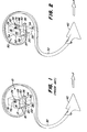
- Fig. 1 eine perspektivische Darstellung einer bekannten Befestigungsvorrichtung für eine Zinke,
- Fig. 2 die erfindungsgemäße Befestigungsvorrichtung für eine Zinke,
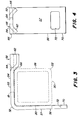
- Fig. 3 eine Seitenansicht der Zinke mit der zugehörigen Befestigungsvorrichtung gemäß Fig. 2,
- Fig. 4 eine Vorderansicht der Befestigungsvorrichtung gemäß Fig. 3.
- 1 is a perspective view of a known fastening device for a tine,
- 2 shows the fastening device according to the invention for a prong,
- 3 shows a side view of the tine with the associated fastening device according to FIG. 2,
- 4 shows a front view of the fastening device according to FIG. 3.
In der Zeichnung ist in Fig. 2 mit 32 eine S-förmige Zinke bezeichnet, die an einem Träger 22 mittels einer Befestigungsvorrichtung an einer mit 50 bezeichneten Stelle angeschlossen ist. Die hierzu notwendige Halterung 52 der Befestigungsvorrichtung besteht aus einem ersten und zweiten Schenkel 54 und 56 mit flach ausgebildeten Flanschteilen 55 und 57, die auf der Oberseite 18 und der Rückseite 20 des Trägers 22 aufliegen. Der Schenkel 54 der Halterung 52 weist einen Steg bzw. einen hervorstehenden Teil bzw. Endteil 58 auf, der mit nach unten abgewinkelten Seitenteilen 62 ausgerüstet ist, die mit dem Mittelstück des Steges 58 ein in etwa umgekehrt V-förmig ausgebildetes Profil ergeben. Der Steg 58 ist mittig mit einer Bohrung bzw. Schlitzöffnung 64 versehen (siehe Fig. 3 und 4), um einen Befestigungsbolzen 40 aufzunehmen. Die Bohrung bzw. die Schlitzöffnung 64 erstreckt sich in Richtung des Steges 34. Die Seitenteile 62 sind mit dem Flanschteil 55 des Schenkels 54 verbunden. Hierzu gehen die nach unten abgewinkelten Seitenteile 62 allmählich in den Flanschteil 55 über. Die Übergangsstelle zwischen den Seitenteilen 62 und dem Flanschteil 55 ist mit 66 bezeichnet, die an den oberen Eckteil, der durch die Oberseite 18 und eine Frontseite 28 des Trägers 22 gebildet ist, angepaßt ist. Wie aus Fig. 3 hervorgeht, ist die Übergangsstelle bzw. der bogenförmig verlaufende Teil 66 so ausgebildet, daß er in Verbindung mit dem Flanschteil 57 auf den Träger 22 aufgeklemmt werden kann. Hierzu wird der Befestigungsbolzen 40 angezogen und zieht den Steg 58 sowie den Flanschteil 57 nach unten gegen die Oberfläche der Oberseite 18 des Trägers 22.In the drawing, 32 denotes an S-shaped prong in FIG. 2, which is connected to a
Der Steg 58 kann beispielsweise in einem Gesenk gefertigt werden und somit die gewünschte Vertiefung bzw. den Querschnitt (siehe Fig. 4) erhalten. Somit kann die Biegefestigkeit des Flachmetalls für die Halterung 52 mit einer bestimmten Breite und Dicke erhöht werden.The
Der Schenkel 56 ist mit einer unteren Kante 70 versehen, in deren Bereich eine Durchdringung bzw. Langlochöffnung 72 vorgesehen ist, die zur Aufnahme eines horizontal verlaufenden Steges 34 der Zinke 32 dient. Hierzu verläuft der Steg 34 unterhalb einer Unterseite 30 des Trägers 22. Der Befestigungsbolzen 40 wird in eine entsprechende im Steg 34 bzw. im Bereich seines Endes 36 vorgesehene Bohrung von unten eingeführt und dann durch die Bohrung 64 im Steg 58 geführt. Der Befestigungsbolzen 40 läßt sich mit einer Mutter 76 sichern, die hierzu von oben her auf den Befestigungsbolzen 40 aufgeschraubt wird und dadurch gegen die Oberfläche des Steges 58 zur Anlage bringbar ist.The
Durch Anziehen der Mutter 76 wird der geformte Steg 58 mit seinem gekrümmten Formteil 66 fest gegen den oberen Eckteil des Trägers 22 gedrückt, wobei der Steg 34 von unten gegen die Unterseite 30 des Trägers 22 gepreßt wird.By tightening the
Die Schenkel 54 und 56 sind in etwa rechtwinklig zueinander ausgerichtet, wobei der Winkel (siehe Fig. 3) etwas kleiner als 90° sein kann. Hierdurch wird ein Rattern der unteren Kante bzw. des unteren Endes 70 und des übrigen Teils des Schenkels 56 vermieden, wenn der Befestigungsbolzen 40 angezogen ist. Ebenso wird dadurch verhindert, daß der Schenkel 56 gegen die Rückseite 20 des Trägers 22 schlägt, da der Befestigungsbolzen 40 die Halterung 52 sowie das zugehörige Eckteil nach vorne und unten zieht, wobei diese Bewegung der Halterung durch den gekrümmten Formteil 66 unterstützt wird, der durch Anziehen des Befestigungsbolzens 40 gewährleistet, daß der Schenkel 56 fast vollständig plan gegen die Rückseite 20 und der Schenkel 54 gegen die Oberseite 18 des Trägers 22 angepreßt wird.The
Claims (8)
Applications Claiming Priority (2)
| Application Number | Priority Date | Filing Date | Title |
|---|---|---|---|
| US425778 | 1982-09-28 | ||
| US06/425,778 US4465396A (en) | 1982-09-28 | 1982-09-28 | Shank clamp |
Publications (1)
| Publication Number | Publication Date |
|---|---|
| EP0107005A1 true EP0107005A1 (en) | 1984-05-02 |
Family
ID=23687995
Family Applications (1)
| Application Number | Title | Priority Date | Filing Date |
|---|---|---|---|
| EP83109011A Ceased EP0107005A1 (en) | 1982-09-28 | 1983-09-13 | Mounting clamp for tools, especially for ground-working tools |
Country Status (7)
| Country | Link |
|---|---|
| US (1) | US4465396A (en) |
| EP (1) | EP0107005A1 (en) |
| AU (1) | AU555700B2 (en) |
| CA (1) | CA1212568A (en) |
| DK (1) | DK444483A (en) |
| ES (1) | ES282332Y (en) |
| ZA (1) | ZA837154B (en) |
Cited By (1)
| Publication number | Priority date | Publication date | Assignee | Title |
|---|---|---|---|---|
| EP2451263A1 (en) * | 2009-07-09 | 2012-05-16 | Väderstad-Verken AB | Mounting of a tool on an agricultural machine |
Families Citing this family (6)
| Publication number | Priority date | Publication date | Assignee | Title |
|---|---|---|---|---|
| US5133415A (en) * | 1990-10-24 | 1992-07-28 | Kent Manufacturing Co., Inc. | Cultivator shank assembly |
| US5335735A (en) * | 1990-10-24 | 1994-08-09 | Kent Manufacturing Co., Inc. | Cultivator shank assembly with cammed shank end receiver |
| DK173276B1 (en) | 1998-02-05 | 2000-06-05 | Kongskilde Ind As | Clamp, method of manufacture of clamp, and agricultural machine using the clamp |
| SE0500263L (en) * | 2005-02-02 | 2005-11-08 | Vaederstad Verken Ab | Device at a spring stick or the like for an agricultural machine |
| US9504197B2 (en) | 2013-09-03 | 2016-11-29 | Cnh Industrial America Llc | Disc blade clamping device |
| US20220132719A1 (en) * | 2020-10-30 | 2022-05-05 | Honey Bee Manufacturing Ltd. | Agricultural implement with tine assembly |
Citations (3)
| Publication number | Priority date | Publication date | Assignee | Title |
|---|---|---|---|---|
| US3827505A (en) * | 1972-08-04 | 1974-08-06 | Royal Industries | Mounting clamp for spring tooth |
| FR2310687A1 (en) * | 1975-05-16 | 1976-12-10 | Anjou Atel Mec | Clamp for harrow tine on machine chassis - has end of tine bolted to L-shaped bracket with slot and spring tangs |
| FR2507709A1 (en) * | 1981-06-16 | 1982-12-17 | Kongskilde Koncernselskab As | ANGLE FIXING WITH BOLT OF TWO BAR-SHAPED ELEMENTS THAT CROSS EACH OTHER, IN PARTICULAR TIGHTENING OF A HERBS TOOTH ON A SUPPORT BAR |
Family Cites Families (3)
| Publication number | Priority date | Publication date | Assignee | Title |
|---|---|---|---|---|
| US1394904A (en) * | 1920-07-09 | 1921-10-25 | Badger Mfg Corp | Clamp |
| US3896883A (en) * | 1973-01-12 | 1975-07-29 | Varlen Corp | Cultivator tooth assembly |
| US4050524A (en) * | 1976-05-17 | 1977-09-27 | Kent Manufacturing Co., Inc. | Cultivator tooth clamp |
-
1982
- 1982-09-28 US US06/425,778 patent/US4465396A/en not_active Expired - Lifetime
-
1983
- 1983-08-23 AU AU18321/83A patent/AU555700B2/en not_active Ceased
- 1983-08-24 CA CA000435296A patent/CA1212568A/en not_active Expired
- 1983-09-13 EP EP83109011A patent/EP0107005A1/en not_active Ceased
- 1983-09-26 ZA ZA837154A patent/ZA837154B/en unknown
- 1983-09-27 ES ES1983282332U patent/ES282332Y/en not_active Expired
- 1983-09-28 DK DK444483A patent/DK444483A/en not_active Application Discontinuation
Patent Citations (3)
| Publication number | Priority date | Publication date | Assignee | Title |
|---|---|---|---|---|
| US3827505A (en) * | 1972-08-04 | 1974-08-06 | Royal Industries | Mounting clamp for spring tooth |
| FR2310687A1 (en) * | 1975-05-16 | 1976-12-10 | Anjou Atel Mec | Clamp for harrow tine on machine chassis - has end of tine bolted to L-shaped bracket with slot and spring tangs |
| FR2507709A1 (en) * | 1981-06-16 | 1982-12-17 | Kongskilde Koncernselskab As | ANGLE FIXING WITH BOLT OF TWO BAR-SHAPED ELEMENTS THAT CROSS EACH OTHER, IN PARTICULAR TIGHTENING OF A HERBS TOOTH ON A SUPPORT BAR |
Non-Patent Citations (1)
| Title |
|---|
| BRÜNEN UND CO., "Federzinken für Kultureggen", Brochüre, DLG. München, 19-26 Mai 1968 * |
Cited By (2)
| Publication number | Priority date | Publication date | Assignee | Title |
|---|---|---|---|---|
| EP2451263A1 (en) * | 2009-07-09 | 2012-05-16 | Väderstad-Verken AB | Mounting of a tool on an agricultural machine |
| EP2451263A4 (en) * | 2009-07-09 | 2012-12-05 | Vaederstad Verken Ab | Mounting of a tool on an agricultural machine |
Also Published As
| Publication number | Publication date |
|---|---|
| US4465396A (en) | 1984-08-14 |
| AU555700B2 (en) | 1986-10-02 |
| ZA837154B (en) | 1985-05-29 |
| DK444483A (en) | 1984-03-29 |
| DK444483D0 (en) | 1983-09-28 |
| CA1212568A (en) | 1986-10-14 |
| ES282332Y (en) | 1985-12-16 |
| AU1832183A (en) | 1984-04-05 |
| ES282332U (en) | 1985-05-01 |
Similar Documents
| Publication | Publication Date | Title |
|---|---|---|
| DE3744176C2 (en) | ||
| DE7532429U (en) | HANGING DEVICE, ESPECIALLY FOR A CEILING OR PARTS THEREOF | |
| DE3152006A1 (en) | CUTTING TOOL FOR METAL WITH INTERCHANGEABLE CUTTING INSERTS | |
| EP0389604A1 (en) | Clamping device | |
| CH659613A5 (en) | FIXING CLAMP. | |
| DE4222494C2 (en) | Roof racks for vehicles | |
| EP0107005A1 (en) | Mounting clamp for tools, especially for ground-working tools | |
| WO2008098744A1 (en) | Punching tool, in particular slotting tool | |
| EP0479818B1 (en) | Parallel and angle stop | |
| EP2884870A1 (en) | Adapter device for a drawer | |
| DE60029277T2 (en) | Clamping device for a cutting insert | |
| DE2225747C2 (en) | Cutting tool for machining | |
| DE60214242T2 (en) | Structure for holding a body part | |
| DE3135881C1 (en) | Spring clamps | |
| DE3204354C2 (en) | Angle fitting for clamping a harrow tine | |
| DE4137618C2 (en) | ||
| DE102005027818B4 (en) | Handle with universally usable knife blade | |
| DE3500423A1 (en) | Hinge, especially for furniture | |
| DE6800555U (en) | LOCKABLE CONTAINER TO ACCEPT TOOLS, BATTERY OR. DGL. | |
| EP0118077A2 (en) | Mitring stop | |
| EP0809748B1 (en) | Chisel holder | |
| DE202004012350U1 (en) | Connection fitting for plates, especially for trays | |
| DE2928871C2 (en) | ||
| DE2644336C2 (en) | Carrying device for furniture components | |
| DE1609301C3 (en) | Covering device for expansion joints |
Legal Events
| Date | Code | Title | Description |
|---|---|---|---|
| PUAI | Public reference made under article 153(3) epc to a published international application that has entered the european phase |
Free format text: ORIGINAL CODE: 0009012 |
|
| AK | Designated contracting states |
Designated state(s): AT DE FR GB |
|
| EL | Fr: translation of claims filed | ||
| 17P | Request for examination filed |
Effective date: 19841026 |
|
| STAA | Information on the status of an ep patent application or granted ep patent |
Free format text: STATUS: THE APPLICATION HAS BEEN REFUSED |
|
| 18R | Application refused |
Effective date: 19871123 |
|
| RIN1 | Information on inventor provided before grant (corrected) |
Inventor name: SUNDBERG, JOHN DAVID Inventor name: MEINERT, HARRY MATHAIS |