EP0118077A2 - Mitring stop - Google Patents
Mitring stop Download PDFInfo
- Publication number
- EP0118077A2 EP0118077A2 EP84101782A EP84101782A EP0118077A2 EP 0118077 A2 EP0118077 A2 EP 0118077A2 EP 84101782 A EP84101782 A EP 84101782A EP 84101782 A EP84101782 A EP 84101782A EP 0118077 A2 EP0118077 A2 EP 0118077A2
- Authority
- EP
- European Patent Office
- Prior art keywords
- index
- rail
- stop
- workpiece
- pin
- Prior art date
- Legal status (The legal status is an assumption and is not a legal conclusion. Google has not performed a legal analysis and makes no representation as to the accuracy of the status listed.)
- Granted
Links
- 230000000149 penetrating effect Effects 0.000 claims 1
- 238000009434 installation Methods 0.000 description 3
- 238000004519 manufacturing process Methods 0.000 description 3
- 238000011161 development Methods 0.000 description 2
- 230000018109 developmental process Effects 0.000 description 2
- 238000003780 insertion Methods 0.000 description 2
- 230000037431 insertion Effects 0.000 description 2
- 239000011295 pitch Substances 0.000 description 2
- 238000006073 displacement reaction Methods 0.000 description 1
- 230000008092 positive effect Effects 0.000 description 1
Images
Classifications
-
- B—PERFORMING OPERATIONS; TRANSPORTING
- B27—WORKING OR PRESERVING WOOD OR SIMILAR MATERIAL; NAILING OR STAPLING MACHINES IN GENERAL
- B27B—SAWS FOR WOOD OR SIMILAR MATERIAL; COMPONENTS OR ACCESSORIES THEREFOR
- B27B25/00—Feeding devices for timber in saw mills or sawing machines; Feeding devices for trees
- B27B25/10—Manually-operated feeding or pressing accessories, e.g. pushers
-
- B—PERFORMING OPERATIONS; TRANSPORTING
- B27—WORKING OR PRESERVING WOOD OR SIMILAR MATERIAL; NAILING OR STAPLING MACHINES IN GENERAL
- B27G—ACCESSORY MACHINES OR APPARATUS FOR WORKING WOOD OR SIMILAR MATERIALS; TOOLS FOR WORKING WOOD OR SIMILAR MATERIALS; SAFETY DEVICES FOR WOOD WORKING MACHINES OR TOOLS
- B27G5/00—Machines or devices for working mitre joints with even abutting ends
- B27G5/02—Machines or devices for working mitre joints with even abutting ends for sawing mitre joints; Mitre boxes
- B27G5/023—Machines or devices for working mitre joints with even abutting ends for sawing mitre joints; Mitre boxes the mitre angle being adjusted by positioning a workpiece relative to a fixed saw
Definitions
- the workpiece stop is indeed provided with a rear projection which has a slot guide for a clamping screw which can be tightened by means of a nut and which is provided with a through hole for inserting the index pin.
- This arrangement which serves to enable the setting of intermediate angles by moving the clamping screw within the associated slot guide, also allowed an adjustment of the stop edge of the workpiece stop with respect to a reference line, e.g. B. with respect to the working plane of the cutting tool.
- a reference line e.g. B.
- the workpiece stop has an index rail which is pivotably mounted on the workpiece holder about the axis perpendicular to the support surface of the workpiece holder and has an exact fit for the index pin and an index rail on the latter with a degree of freedom of rotation relative to the index pin by a bearing surface of the workpiece holder vertical axis has pivotally mounted stop rail, the pivoting position of which can be adjusted relative to the index rail by means of an adjusting device.
- the arrangement according to the invention is therefore based on a two-part workpiece stop.
- the two-part design of the workpiece stop advantageously enables an exact adjustment of the stop rail which can be pivoted with respect to the index rail and has a stop edge with respect to a reference line, for example with an index rail fixed by the index pin. B. with respect to the feed direction or the adjacent side of the machine table or the working plane of the cutting tool.
- Such an adjustability is advantageous when installing for the first time, since manufacturing and assembly tolerances cannot be eliminated and the installation site generally differs from the assembly site in terms of local conditions.
- the Position of the index rail remains advantageously fixed during the adjustment of the stop rail relative to the workpiece holder, it is also ensured that in the case of a scale associated with the index rail, provided with an angular division, despite a possible shift in the angular position of the stop rail, no change in the position of the scale assigned reading edge of the index rail results, which has a positive effect on the achievable setting accuracy and ease of use. From this it can be seen that the invention solves the task set with simple and therefore inexpensive means.
- index rail and the adjusting rail mounted thereon have a common pivot axis.
- the index rail can expediently have a U-shaped cross section which is open towards the stop rail, the stop rail being able to engage between the legs of the U rail forming the index rail, which results in a wobble-proof reception of the stop rail and thus high repeatability.
- this can simply have an appropriate adjustment play in relation to the index pin which interacts with the index rail without play.
- an adjusting device can be provided for adjusting the stop rail, which is provided with an adjusting screw acting on the index rail and on the stop rail, on which the index rail and the stop rail each have a clamping nut and one of these stops can be fixed, at least one of these stops can simply be designed as an adjustable nut.
- a longitudinal guide 2 is arranged parallel to the table edge on the left, seen in the feed direction, parallel to the saw blade plane.
- the table end is provided with mounting plates 3, on which the longitudinal guide 2 receiving carrying straps 4 can be detachably fixed by means of a plug and clamp lock.
- On the longitudinal guide 2 is a a slide carriage 5 forming a workpiece holder is slidably mounted. The displacement movement is limited by end stops, which are designed here as the spring bolt 6 passing through the profile tube forming the longitudinal guide 2, which can be retracted against the force of the release spring acting thereon, so that the slide 5 can be removed from the longitudinal guide 2.
- the carriage 5 has a table top 7 forming a workpiece support surface, which is provided with a workpiece stop 8 arranged transversely to the feed direction, ie transversely to the longitudinal direction of the longitudinal guide 2.
- the workpiece stop is pivotable for making miter cuts about an axis a perpendicular to the support surface of the table top 7.
- the workpiece stop 8 is, as can best be seen from FIGS. 2 and 3, in two parts and consists of an index rail 9 pivotably mounted on the table top 7 about the axis a and a stop rail 10 pivotably mounted thereon about an axis coaxial with the axis a
- a spring pin 11 is simply provided which penetrates the index rail 9 and the stop rail 10 without play and engages without play in a table-side bearing bore.
- the index rail 9 is, as can best be seen from FIG. 3, U-shaped in cross section and arranged in such a way that its parallel legs 12 overlap or underneath the stop rail 10, which gives the stop rail 10 excellent freedom from wobble.
- the stop rail 10 consists of a between the legs 12 of the Indexing rail 9 engaging support tube 13 and an extension bar 14 placed thereon, which can be detachably fixed thereto by means of clamping screws 15.
- the pivotability of the workpiece stop 8 about the pivot axis a allows the setting of any desired miter angle.
- the pivotable workpiece stop 8 can be fixed in a rotationally fixed manner relative to the table top 7.
- a clamping screw 16 is provided which engages on the index rail 9 and extends through an arcuate longitudinal groove 17 of the table top 7.
- the clamping screw 16 is assigned a manually operable clamping nut 18 which is arranged in the region of the underside of the table and by means of which a clamp closure can be produced.
- the arcuate groove 17 follows the course of an ice around the axis a with the distance of the clamping screw 16 from the axis a corresponding radius.
- the clamping screw 16 extends through the legs 12 of the index rail 9, so that they are pressed with a corresponding clamping force on the support tube 13 of the stop rail 10 encompassed thereby.
- the stiffness of the support tube 13 ensures that the U-shaped index rail is not deformed under the action of the clamping force.
- the clamping nut 18 is loosened, any desired angular position can be set within the arcuate groove 17.
- the table top 7 is designed as a scale support for a molded-in or glued-on scale 19, to which an adjustment edge 20 of the index rail is assigned, as shown in FIG. 2.
- the setting edge 20 has a sharp edge on the scale side.
- the index rail 9 is simply punched out in the area of its rear side to form the setting edge 20.
- the zero position of the workpiece stop 8 i.e. the position in which the workpiece-side stop edge of the workpiece stop runs exactly at an angle of 90 degrees to the feed direction of the slide 5 or to the plane of the associated saw blade or to the table edge parallel to the saw blade, is in the region of the middle of the Scale 19 or the arcuate groove 17, which enables a two-sided deflection of the workpiece stop, ie a deflection over the zero position both in the positive sense and in the negative sense.
- the workpiece stop can be fixed by means of an index pin 21, which can be detachably received on the index rail 9 and inserted into an assigned index hole 22 of the table top 7.
- the index pin 21 engages through the legs 12 of the index rail 9 and through that of the legs 12 encompassed support tube 13 of the stop rail 10 therethrough.
- a precise fit is provided in the region of the legs 12.
- an index-shaped slot 23 is assigned to the index pin 21, which enables the stop rail 10 to be deflected relative to the index rail 9.
- This possibility of relative movement between index rail 9 and stop rail 10 is necessary in order to be able to carry out a precise adjustment of the stop edge on the workpiece in the zero position.
- Such adjustment is at least at least when re-installing a machine, in order to compensate for inaccuracies resulting from the local conditions of the installation site.
- an adjusting device 24 indicated only by its center line, is provided, by means of which the stop rail 10, which is pivotable relative to the index rail 9 and is mounted thereon, can be adjusted.
- the actuating device 24 here, as shown in FIG. 3, consists of a on the stop rail 10, i.e. ar the support tube 13, and on the index rail 9 engaging clamping screw 25, which is supported on the stop rail side with its head 26 and index rail side with an adjusting nut 27.
- the distance between the head 26 and the adjusting nut 27, which is set by a corresponding rotation of the adjusting nut 27, and thus the angle set between the index rail 9 and the stop rail 10, can be fixed by the clamping nuts 28 assigned to the head 26 or the adjusting nut 27, which lock the indexing rail 9 against the assigned adjusting lever 27 and clamp the support tube 13 of the stop rail 10 against the assigned screw head 26.
- a plurality of index holes 22 are provided on a pitch circle around the pivot axis a, for quickly fixing the workpiece stop in all important angular positions.
- the partial circle of the index holes 22 parallel to the arcuate groove 17 or to the scale 19 leads in both directions beyond the zero position of the workpiece stop.
- the index holes 22 provided can be arranged with the same or different pitches.
- the index holes are 15 degrees apart arranged, whereby the important angles of 30 degrees and 45 degrees are detected. In some cases, an even finer division, for example a 5-degree division, can also be useful. In this case, approximately two index hole partial circles can be provided, on which the index holes can be arranged offset from one another.
- the index rail 9 and the support tube 13 of the stop rail 10 would also have to be provided with two radially staggered receptacles for an index pin 21.
- the angular positions specified by index holes 22 can be determined simply by inserting the index pin 21.
- the clamping screw 16 is therefore only required in the range of the intermediate positions which can be set with the aid of the scale 19 and the setting edge 20.
- the index holes 22 are designed as simple fitting bores to which a cylindrical section of the index pin 21 is assigned. It would also be conceivable to design the index holes 22 as conical holes, to which conical sections of the index pin 21 are assigned. In such a case, it would be ensured that the index pin 21 always comes to rest on the hole-side seat in a full and play-free manner.
- this is provided with a button-like handle 29 arranged in the region of its upper end. In the area of its lower end, an insertion phase 30 can be provided, which facilitates the insertion of the index pin 21 into the associated receptacles on the workpiece stop and on the table top.
Landscapes
- Life Sciences & Earth Sciences (AREA)
- Engineering & Computer Science (AREA)
- Mechanical Engineering (AREA)
- Wood Science & Technology (AREA)
- Forests & Forestry (AREA)
- Sawing (AREA)
- Character Spaces And Line Spaces In Printers (AREA)
- Lubricants (AREA)
- Milling, Drilling, And Turning Of Wood (AREA)
Abstract
Description
gewährleistet, wenn die Winkellage der Indexlöcher bezüglich der Bezugslinie genau stimmt. Dies ist jedoch auch bei einem hohen Herstellungsaufwand praktisch nicht zu erreichen. Der Grund dafür ist darin zu sehen, daß gewisse Fertigungs- und Montagetoleranzen nicht vermeidbar sind und daß der Einsatzstandort der mit dem Gehrungsanschlag versehenen Maschine von den örtlichen Gegebenheiten her, z. B. der Fundamentbeschaffenheit etc., vom Montagestandort abweicht.guaranteed if the angular position of the index holes with respect to the reference line is correct. However, this is practically not achievable even with a high manufacturing cost. The reason for this is the fact that certain manufacturing and assembly tolerances are unavoidable and that the location of the machine provided with the miter fence depends on the local conditions, e.g. B. the foundation condition etc., deviates from the installation site.
Bei der Anordnung gemäß US-PS 11 13 152 ist der Werkstückanschlag zwar mit einer rückwärtigen Auskragung versehen, die eine Schlitzführung für eine mittels einer Mutter festspannbare Klemmschraube aufweist, die mit einer Durchgangsbohrung zum Durchstecken des Indexstifts versehen ist. Diese Anordnung, die dazu dient, durch Verschieben der Klemmschraube innerhalb der zugeordneten Schlitzführung die Einstellung von Zwischenwinkeln zu ermöglichen, ermöglichte zwar auch eine Justierung der Anschlagkante des Werkstückanschlags bezüglich einer Bezugslinie, z. B. bezüglich der Arbeitsebene des Schnittwerkzeugs. Dies ist jedoch nicht nur in der US-PS 11 13 152 nicht angesprochen, sondern würde auch die Bedienung der bekannten Anordnung sehr erschweren, da die Justierung bei jeder Einstellung eines Zwischenwinkels verloren ginge und daher anschließend neu durchgeführt werden müßte, was einen hohen Zeitaufwand erforderte. Ganz abgesehen davon ist davon auszugehen, daß sich bei der Anordnung gemäß US-PS 11 13 152 im Falle einer Justierung der Anschlagkante Abweichungen zwischen der tatsächlichen Stellung der Anschlagkante und dem auf einer zugeordneten Skala angezeigten Wert ergeben könnten. Hiervon ausgehend ist es daher die Aufgabe der vorliegenden Erfindung unter Vermeidung der Nachteile der bekannten Lösung eine Anordnung eingangs erwähnter Art so zu verbessern, daß trotz einer exakten Justierbarkeit der Anschlagkante des Werkstückanschlags bezüglich einer maschinenfesten Bezugslinie eine schnelle Einstellung der Nullstellung und/oder bevorzugter Winkelstellungen mittels des Indexstifts möglich ist.In the arrangement according to US-PS 11 13 152, the workpiece stop is indeed provided with a rear projection which has a slot guide for a clamping screw which can be tightened by means of a nut and which is provided with a through hole for inserting the index pin. This arrangement, which serves to enable the setting of intermediate angles by moving the clamping screw within the associated slot guide, also allowed an adjustment of the stop edge of the workpiece stop with respect to a reference line, e.g. B. with respect to the working plane of the cutting tool. However, this is not only not addressed in US Pat. No. 11,132,152, but would also make operation of the known arrangement very difficult, since the adjustment would be lost with each setting of an intermediate angle and would therefore have to be carried out again afterwards, which required a great deal of time . Quite apart from this, it can be assumed that in the arrangement according to US Pat. No. 11,132,152, if the stop edge is adjusted, there could be deviations between the actual position of the stop edge and the value displayed on an assigned scale. Proceeding from this, it is therefore the object of the present invention, while avoiding the disadvantages of the known solution, to improve an arrangement of the type mentioned in such a way that, despite an exact adjustability of the stop edge of the workpiece stop with respect to a machine-fixed reference line, a quick setting of the zero position and / or preferred angular positions by means of of the index pin is possible.
Diese Aufgabe, wird erfindungsgemäß dadurch gelöst, daß der Werkstückanschlag eine um die zur Auflagefläche der Werkstückaufnahme lotrechte Achse schwenkbar auf der Werkstückaufnahme gelagerte, eine genaue Passung für den Indexstift aufweisende Indexschiene und eine auf dieser mit Schwenkfreiheitsgrad gegenüber dem Indexstift um eine ebenfalls zur Auflagefläche der Werkstückaufnahme lotrechte Achse schwenkbar gelagerte Anschlagschiene aufweist, deren Schwenkstellung mittels einer Stelleinrichtung gegenüber der Indexschiene einstellbar ist.This object is achieved according to the invention in that the workpiece stop has an index rail which is pivotably mounted on the workpiece holder about the axis perpendicular to the support surface of the workpiece holder and has an exact fit for the index pin and an index rail on the latter with a degree of freedom of rotation relative to the index pin by a bearing surface of the workpiece holder vertical axis has pivotally mounted stop rail, the pivoting position of which can be adjusted relative to the index rail by means of an adjusting device.
Der erfindungsgemäßen Anordnung liegt demnach ein zweiteiliger Werkstückanschlag zugrunde. Die zweiteilige Ausführung des Werkstückanschlags ermöglicht in vorteilhafter Weise bei durch den Indexstift fixierter Indexschiene eine genaue Justierung der gegenüber der Indexschiene schwenkbaren, eine Anschlagkante aufweisenden Anschlagschiene bezüglich einer Bezugslinie, z. B. bezüglich der Vorschubrichtung bzw. der benachbarten Maschinentischseitenkante oder der Arbeitsebene des Schnittwerkzeugs. Bei der Erstanbringung ist eine derartige Justierbarkeit von Vorteil, da sich Herstellungs- und Montagetoleranzen nicht ausschalten lassen und der Aufstellungsort von den lokalen Verhältnissen her in der Regel vom Montagestandort abweicht. Da die Stellung der Indexschiene während der Justierung der Anschlagschiene gegenüber der Werkstückaufnahme in vorteilhafter Weise fixiert bleibt, ist auch sichergestellt, daß sich im Falle einer der Indexschiene zugeordneten, mit einer Winkelteilung versehenen Skala trotz einer möglichen Verschiebung der Winkellage der Anschlagschiene keine Änderung der Lage der der Skala zugeordneten Ablesekante der Indexschiene ergibt, was sich positiv auf die erzielbare Einstellgenauigkeit und Bedienungsfreundlichkeit auswirkt. Hieraus ist erkennbar, daß die Erfindung die ihr gestellte Aufgabe mit einfachen und daher kostengünstigen Mitteln löst.The arrangement according to the invention is therefore based on a two-part workpiece stop. The two-part design of the workpiece stop advantageously enables an exact adjustment of the stop rail which can be pivoted with respect to the index rail and has a stop edge with respect to a reference line, for example with an index rail fixed by the index pin. B. with respect to the feed direction or the adjacent side of the machine table or the working plane of the cutting tool. Such an adjustability is advantageous when installing for the first time, since manufacturing and assembly tolerances cannot be eliminated and the installation site generally differs from the assembly site in terms of local conditions. Since the Position of the index rail remains advantageously fixed during the adjustment of the stop rail relative to the workpiece holder, it is also ensured that in the case of a scale associated with the index rail, provided with an angular division, despite a possible shift in the angular position of the stop rail, no change in the position of the scale assigned reading edge of the index rail results, which has a positive effect on the achievable setting accuracy and ease of use. From this it can be seen that the invention solves the task set with simple and therefore inexpensive means.
Eine weitere vorteilhafte Maßnahme kann darin bestehen, daß die Indexschiene und die hierauf gelagerte Stellschiene eine gemeinsame Schwenkachse aufweisen. Diese Maßnahme ergibt eine sehr kompakte Bauweise. Zweckmäßig kann dabei die Indexschiene eine U-förmigen, zur Anschlagschiene hin offenen Querschnitt aufweisen, wobei die Anschlagschiene zwischen die Schenkel der die Indexschiene bildenden U-Schiene eingreifen kann, was eine wackelsichere Aufnahme der Anschlagschiene und damit eine hohe Wiederholungsgenauigkeit ergibt. Zur Bewerkstelligung der gewünschten Justierbarkeit der Anschlagschiene kann diese einfach gegenüber dem spielfrei mit der Indexschiene zusammenwirkenden Indexstift ein entsprechendes Justierungsspiel aufweisen.Another advantageous measure can be that the index rail and the adjusting rail mounted thereon have a common pivot axis. This measure results in a very compact design. The index rail can expediently have a U-shaped cross section which is open towards the stop rail, the stop rail being able to engage between the legs of the U rail forming the index rail, which results in a wobble-proof reception of the stop rail and thus high repeatability. To achieve the desired adjustability of the stop rail, this can simply have an appropriate adjustment play in relation to the index pin which interacts with the index rail without play.
In weiterer Fortbildung der übergeordneten Maßnahmen kann zur Justierung der Anschlagschiene eine Stelleinrichtung vorgesehen sein, die mit einer an der Indexschiene und an der Anschlagschiene angreifenden Stellschraube versehen ist, an der die Indexschiene und die Anschlagschiene durch jeweils eine Spannmutter und einen dieser zugeordneten Anschlag fixierbar sind, wobei mindestens einer dieser Anschläge einfach als verstellbare Mutter ausgebildet sein kann. Diese Ausbildung gestattet eine einfache und zuverlässige Justierung der Anschlagschiene sowie eine exakte Festlegung der Anschlagschiene gegenüber der Indexschiene nach erfolgter Fixierung.In a further development of the superordinate measures, an adjusting device can be provided for adjusting the stop rail, which is provided with an adjusting screw acting on the index rail and on the stop rail, on which the index rail and the stop rail each have a clamping nut and one of these stops can be fixed, at least one of these stops can simply be designed as an adjustable nut. This design allows a simple and reliable adjustment of the stop rail and an exact fixing of the stop rail relative to the index rail after fixation.
Weitere zweckmäßige Ausgestaltungen und vorteilhafte Weiterbildungen der übergeordneten Maßnahmen ergeben sich aus der nachstehenden Beschreibung eines Ausführungsbeispiels anhand der Zeichnung in Verbindung mit den restlichen Unteransprüchen.Further expedient refinements and advantageous developments of the superordinate measures result from the following description of an exemplary embodiment with reference to the drawing in conjunction with the remaining subclaims.
In der Zeichnung zeigen:
- Figur 1 eine Frontansicht eines mit einem seitlich angebauten, einen Werkstüchkanschlag aufweisenden Schiebeschlitten versehenen Ereissägentisches,
Figur 2 eine Draufsicht auf den Schiebeschlitten gemäß Figur 1 undFigur 3 einen Schnitt entlang der Linie III/III inFigur 2.
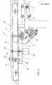
- FIG. 1 shows a front view of an ice saw table with a sliding carriage that is attached to the side and has a workpiece stop,
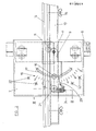
- Figure 2 is a plan view of the sliding carriage according to Figure 1 and
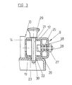
- FIG. 3 shows a section along the line III / III in FIG. 2.
An den in Figur 1 durch strichpunktierte Linien angedeuteten Kreissägentisch 1 ist eine parallel zur in Vorschubrichtung gesehen linken, zur Sägeblattebenen parallelen Tischkante angeordnete Längsführung 2 angebaut. Hierzu ist die Tischstirnseite mit Anbauplatten 3 versehen, an denen die Längsführung 2 aufnehmende Traglaschen 4 durch Steck- und Klemmverschluß lösbar fixierbar sind. Auf der Längsführung 2 ist ein eine Werkstückaufnahme bildender Schiebeschlitten 5 verschiebbar gelagert. Die Verschiebebewegung ist durch Endanschläge begrenzt, die hier als das die Längsführung 2 bildende Profilrohr durchsetzende Federbolzen 6 ausgebildet sind, die entgegen der Kraft der hieran angreifenden Ausrückfeder zurückgezogen werden können, so daß der Schlitten 5 von der Längsführung 2 abnehmbar ist. Der Schlitten 5 besitzt eine eine Werkstückauflagefläche bildende Tischplatte 7, die mit einem quer zur Vorschubrichtung, d.h. quer zur Längsrichtung der Längsführung 2 angeordneten Werkstückanschlag 8 versehen ist. Der Werkstückanschlag ist zur Durchführung von Gehrungsschnitten um eine zur Auflagefläche der Tischplatte 7 lotrechte Achse a schwenkbar.On the circular saw table 1, indicated by dash-dotted lines in FIG. 1, a
Der Werkstückanschlag 8 ist, wie am besten den Figuren 2 und 3 entnehmbar ist, zweiteilig ausgebildet und besteht aus einer um die Achse a schwenkbar auf der Tischplatte 7 gelagerten Indexschiene 9 und einer auf dieser hier um eine zur Achse a koaxiale Achse schwenkbar gelagerten Anschlagschiene 10. Zur Bildung der Schwenkachsen von Indexschiene 9 und Anschlagschiene 10 ist hierbei einfach ein die Indexschiene 9 und die Anschlagschiene 10 spielfrei durchsetzender und in eine tischplattenseitige Lagerbohrung spielfrei eingreifender Federstift 11 vorgesehen. Die Indexschiene 9 ist, wie am besten aus Figur 3 erkennbar ist, im Querschnitt U-förmig ausgebildet und so angeordnet, daß ihre parallelen Schenkel 12 die Anschlagschiene 10 über- bzw. untergreifen, was eine ausgezeichnete Wackelfreiheit der Anschlagschiene 10 ergibt. Im dargestellten Ausführungsbeispiel besteht die Anschlagschiene 10 aus einem zwischen die Schenkel 12 der Indexschiene 9 eingreifenden Trägerrohr 13 und einer auf dieses aufgesetzten Verlängerungsleiste 14, die durch Klemmschrauben 15 lösbar hieran festlegbar ist.The workpiece stop 8 is, as can best be seen from FIGS. 2 and 3, in two parts and consists of an
Die Schwenkbarkeit des Werkstückanschlags 8 um die Schwenkachse a gestattet die Einstellung jedes gewünschten Gehrungswinkels. Zur Durchführung entsprechender Schnittarbeiten ist der schwenkbare Werkstückanschlag 8 gegenüber der Tischplatte 7 verdrehsicher fixierbar. Hierzu ist, wie den Figuren 1 und 2 entnommen werden kann, eine Spannschraube 16 vorgesehen, die an der Indexschiene 9 angreift und durch eine bogenförmige Längsnut 17 der Tischplatte 7 hindurchgreift. Der Spannschraube 16 ist eine im Bereich der Tischunterseite angeordnete, von Hand betätigbare Spannmutter 18 zugeordnet, mit welcher ein Klemmverschluß erzeugbar ist. Die bogenförmige Nut 17 folgt dem Verlauf eines Ereises um die Achse a mit dem Abstand der Spannschraube 16 von der Achse a entsprechendem Radius. Im dargestellten Ausführungsbeispiel greift die Spannschraube 16 durch die Schenkel 12 der Indexschiene 9 hindurch, so daß diese bei entsprechender Spannkraft am hiervon umfaßten Trägerrohr 13 der Anschlagschiene 10 angepreßt werden. Die Formsteifigkeit des Trägerrohrs 13 stellt hierbei sicher, daß die U-förmige Indexschiene unter der Wirkung der Spannkraft nicht verformt wird. Bei gelöster Spannmutter 18 ist jede gewünschte Winkelstellung innerhalb der bogenförmigen Nut 17 einstellbar. Hierzu ist die Tischplatte 7 als Skalenträger für eine eingeformte bzw. aufgeklebte Skala 19 ausgebildet, der eine Einstellkante 20 der Indexschiene zugeordnet ist, wie Figur 2 zeigt. Zur Bewerkstelligung einer parallaxenfreien Einstellung weist die Einstellkante 20 eine scharfe skalenseitige Kante auf. Im dargestellten Ausführungsbeispiel ist die Indexschiene 9 zur Bildung der Einstellkante 20 einfach im Bereich ihrer Rückseite entsprechend ausgestanzt.The pivotability of the workpiece stop 8 about the pivot axis a allows the setting of any desired miter angle. To carry out corresponding cutting work, the pivotable workpiece stop 8 can be fixed in a rotationally fixed manner relative to the
Die Nullstellung des Werkstückanschlags 8, d.h. diejenige Stellung, in der die werkstückseitige Anschlagkante des Werkstückanschlags genau unter einem Winkel von 90 Grad zur Vorschubrichtung des Schlittens 5 bzw. zur Ebene des zugeordneten Sägenblatts bzw. zur sägenblattparallelen Tischkante verläuft, befindet sich im Bereich der Mitte der Skala 19 bzw. der bogenförmigen Nut 17, was eine zweisinnige Auslenkung des Werkstückanschlags, d.h. eine Auslenkung über die Nullstellung sowohl im positiven Sinne als auch im negativen Sinne, ermöglicht. In der genannten Nullstellung ist der Werkstückanschlag mittels eines Indexstifts 21 fixierbar, der lösbar auf der Indexschiene 9 aufnehmbar und in ein zugeordnetes Indexloch 22 der Tischplatte 7 einsteckbar ist. Zur Bewerkstelligung einer einwandfreien Wiederholungsgenauigkeit besteht dabei Spielfreiheit sowohl im Bereich der Indexschiene 9 als auch im Bereich der Tischplatte 7. Im dargestellten Ausführungsbeispiel greift der Indexstift 21, wie am besten aus Figur 3 erkennbar ist, durch die Schenkel 12 der Indexschiene 9 und durch das von den Schenkeln 12 umfaßte Trägerrohr 13 der Anschlagschiene 10 hindurch. Im Bereich der Schenkel 12 ist hierbei eine genaue Passung vorgesehen. Im Bereich des Trägerrohrs 13 ist dem Indexstift 21 ein bogenförmiger Schlitz 23 zugeordnet, was eine Auslenkung der Anschlagschiene 10 relativ zur Indexschiene 9 ermöglicht. Diese Relativbewegungsmöglichkeit zwischen Indexschiene 9 und Anschlagschiene 10 ist erforderlich, um eine genaue Justierung der werkstückseitigen Anschlagkante in der Nullstellung durchführen zu können. Eine derartige Justierung ist zumindest bei der Neuaufstellung einer Maschine erforderlich, um Ungenauigkeiten, die sich aus den lokalen Verhältnissen des Aufstellungsorts ergeben, auszugleichen.The zero position of the workpiece stop 8, i.e. the position in which the workpiece-side stop edge of the workpiece stop runs exactly at an angle of 90 degrees to the feed direction of the
Zur Durchführung der Justierung ist eine in Figur 2 lediglich durch ihre Mittellinie angedeutete Stelleinrichtung 24 vorgesehen, mittels welcher die gegenüber der Indexschiene 9 schwenkbare, hierauf gelagerte Anschlagschiene 10 verstellbar ist. Die Stelleinrichtung 24 besteht hier, wie Figur 3 zeigt, aus einer an der Anschlagschiene 10, d.h. ar deren Trägerrohr 13, und an der Indexschiene 9 angreifenden Spannschraube 25, die sich anschlagschienenseitig mit ihrem Kopf 26 und indexschienenseitig mit einer Stellmutter 27 abstützt. Der durch entsprechende Verdrehung der Stellmutter 27 eingestellte Abstand zwischen Kopf 26 und Stellmutter 27 und damit der zwischen Indexschiene 9 und Anschlagschiene 10 eingestellte Winkel ist durch den Kopf 26 bzw. der Stellmutter 27 zugeordnete Spannmuttern 28 fixierbar, welche die Indexschiene 9 gegen die zugeordnete Stellmutzer 27 und das Trägerrohr 13 der Anschlagschiene 10 gegen den zugeordneten Schraubenkopf 26 spannen.To carry out the adjustment, an adjusting
Im dargestellten Ausführungsbeispiel sind, wie am besten aus Figur 2 erkennbar ist, zur schnellen Fixierung des Werkstückanschlags in allen wichtigen Winkelstellungen mehrere, auf einem Teilkreis um die Schwenkachse a angeordnete Indexlöcher 22 vorgesehen. Der zur bogenförmigen Nut 17 bzw. zur Skala 19 parallele Teilkreis der Indexlöcher 22 führt in beiden Richtungen über die Nullstellung des Werkstückanschlags hinaus. Die vorgesehenen Indexlöcher 22 können mit gleicher oder ungleicher Teilung angeordnet sein. Im dargestellten Ausführungsbeispiel sind die Indexlöcher mit einer 15 Grad-Teilung angeordnet, wodurch die wichtigen Winkel von 30 Grad und 45 Grad erfaßt werden. In manchen Fällen kann sich auch eine noch feinere Teilung, z.B. eine 5 Grad-Teilung als zweckmäßig erweisen. In diesem Falle können etwa zwei Indexloch-Teilkreise vorgesehen sein, auf denen die Indexlöcher versetzt gegeneinander angeordnet se n können. Die Indexschiene 9 und das Trägerrohr 13 der Anschlagschiene 10 müßten in diesem Fall ebenfalls mit zwei radial gestaffelten Aufnahmen für einen Indexstift 21 versehen sein. Die durch Indexlöcher 22 vorgegebenen Winkelstellungen sind einfach durch Einstecken des Indexstifts 21 festlegbar. Die Spannschraube 16 wird demnach lediglich im Bereich der mit Hilfe der Skala 19 und der Einstellkante 20 einstellbaren Zwischenstellungen benötigt.In the illustrated embodiment, as can best be seen from FIG. 2, a plurality of
Die Indexlöcher 22 sind im dargestellten Ausführungsbeispielals einfache Paßbohrungen ausgebildet, denen ein zylinderischer Abschnitt des Indexstifts 21 zugeordnet ist. Es wäre auch denkbar, die Indexlöcher 22 als Konuslöcher auszubilden, denen konische Abschnitte des Indexstifts 21 zugeordnet sind. In einem derartigen Fall wäre sichergestellt, daß der Indexstift 21 stets satt und spielfrei am lochseitigen Sitz zur Anlage kommt. Zur Bewerkstelligung einer einfachen Betätigung des Indexstifts 21 ist dieser mit einem im Bereich seines oberen Endes angeordneten knopfartigen Griff 29 versehen. Im Bereich seines unteren Endes kann eine Einführphase 30 vorgesehen sein, welche das Einführen des Indexstifts 21 in die zugeordneten werkstückanschlagseitigen und tischplattenseitigen Aufnahmen erleichtert.In the exemplary embodiment shown, the index holes 22 are designed as simple fitting bores to which a cylindrical section of the
Claims (9)
Priority Applications (1)
| Application Number | Priority Date | Filing Date | Title |
|---|---|---|---|
| AT84101782T ATE48786T1 (en) | 1983-03-02 | 1984-02-21 | MITER STOP. |
Applications Claiming Priority (2)
| Application Number | Priority Date | Filing Date | Title |
|---|---|---|---|
| DE3307287A DE3307287C2 (en) | 1983-03-02 | 1983-03-02 | Miter fence for woodworking machines |
| DE3307287 | 1983-03-02 |
Publications (3)
| Publication Number | Publication Date |
|---|---|
| EP0118077A2 true EP0118077A2 (en) | 1984-09-12 |
| EP0118077A3 EP0118077A3 (en) | 1987-10-14 |
| EP0118077B1 EP0118077B1 (en) | 1989-12-20 |
Family
ID=6192250
Family Applications (1)
| Application Number | Title | Priority Date | Filing Date |
|---|---|---|---|
| EP84101782A Expired EP0118077B1 (en) | 1983-03-02 | 1984-02-21 | Mitring stop |
Country Status (3)
| Country | Link |
|---|---|
| EP (1) | EP0118077B1 (en) |
| AT (1) | ATE48786T1 (en) |
| DE (2) | DE3307287C2 (en) |
Cited By (1)
| Publication number | Priority date | Publication date | Assignee | Title |
|---|---|---|---|---|
| WO2004043635A1 (en) * | 2002-11-14 | 2004-05-27 | Wilhelm Altendorf Gmbh & Co. Kg | Mitre stop |
Families Citing this family (4)
| Publication number | Priority date | Publication date | Assignee | Title |
|---|---|---|---|---|
| DE3915376A1 (en) * | 1989-05-11 | 1990-11-15 | Herbert Lang | Template for mitring or oblique cutting wooden pieces - consists of base board surmounted by movable cross-rail which acts as guide for saw |
| DE19519646C1 (en) * | 1995-05-30 | 1996-09-12 | Scheppach Maschf J | Cross-cut device for circular saw for wood |
| US6530303B1 (en) | 1999-06-10 | 2003-03-11 | Black & Decker Inc. | Table saw |
| CN112589645B (en) * | 2020-11-27 | 2021-12-10 | 张建洁 | Construct dedicated fixed cutting all-in-one of special-shaped steel |
Citations (3)
| Publication number | Priority date | Publication date | Assignee | Title |
|---|---|---|---|---|
| US1113152A (en) * | 1913-11-01 | 1914-10-06 | American Wood Working Machinery Co | Cut-off gage for sawing-machines. |
| US2010882A (en) * | 1934-10-18 | 1935-08-13 | Walker Turner Company Inc | Self-indexing miter gauge |
| US3872761A (en) * | 1973-12-03 | 1975-03-25 | Stanley Works | Mitre box with improved indexing means |
Family Cites Families (2)
| Publication number | Priority date | Publication date | Assignee | Title |
|---|---|---|---|---|
| DE13538C (en) * | J. BRÄUTIGAM in Nürnberg, Weifsgerbergasse 12 | Miter saw | ||
| DE2524341A1 (en) * | 1975-06-02 | 1976-12-16 | Scharwaechter Kg | Angular wooden board cross cutting device - has material pick-up with two interconnected belts and tool guide carrier |
-
1983
- 1983-03-02 DE DE3307287A patent/DE3307287C2/en not_active Expired
-
1984
- 1984-02-21 DE DE8484101782T patent/DE3480776D1/en not_active Expired - Fee Related
- 1984-02-21 AT AT84101782T patent/ATE48786T1/en not_active IP Right Cessation
- 1984-02-21 EP EP84101782A patent/EP0118077B1/en not_active Expired
Patent Citations (3)
| Publication number | Priority date | Publication date | Assignee | Title |
|---|---|---|---|---|
| US1113152A (en) * | 1913-11-01 | 1914-10-06 | American Wood Working Machinery Co | Cut-off gage for sawing-machines. |
| US2010882A (en) * | 1934-10-18 | 1935-08-13 | Walker Turner Company Inc | Self-indexing miter gauge |
| US3872761A (en) * | 1973-12-03 | 1975-03-25 | Stanley Works | Mitre box with improved indexing means |
Cited By (2)
| Publication number | Priority date | Publication date | Assignee | Title |
|---|---|---|---|---|
| WO2004043635A1 (en) * | 2002-11-14 | 2004-05-27 | Wilhelm Altendorf Gmbh & Co. Kg | Mitre stop |
| CN100404180C (en) * | 2002-11-14 | 2008-07-23 | 威尔海姆-阿尔坦道夫两合公司 | Mitre stop |
Also Published As
| Publication number | Publication date |
|---|---|
| EP0118077A3 (en) | 1987-10-14 |
| ATE48786T1 (en) | 1990-01-15 |
| DE3307287A1 (en) | 1984-09-06 |
| DE3480776D1 (en) | 1990-01-25 |
| DE3307287C2 (en) | 1986-01-30 |
| EP0118077B1 (en) | 1989-12-20 |
Similar Documents
| Publication | Publication Date | Title |
|---|---|---|
| EP0144490A2 (en) | Drill or miller guiding device for exchangeable driving machines | |
| EP0315728B1 (en) | Tile cutting device | |
| WO1990002633A2 (en) | Clamping device | |
| EP0116260A2 (en) | Clamping apparatus | |
| EP0118077B1 (en) | Mitring stop | |
| EP0479818B1 (en) | Parallel and angle stop | |
| EP0598218B1 (en) | Tool stand for holding and longitudinally guiding tools, in particular stone drills and -saws | |
| DE4409540A1 (en) | Extension-arm circular saw operated in a stationary position | |
| EP3702100B1 (en) | Stop device | |
| DE3422570A1 (en) | Blade holder for a shear blade on reel slitting machines | |
| DE102009025108B4 (en) | Scroll saw with adjustable work table | |
| EP0799677A2 (en) | Device for receiving motorized tools, in particular for portable circular saws | |
| EP0174640B1 (en) | Trimming appliance for a circular saw bench | |
| EP0117505B1 (en) | Wood working machine | |
| WO2010142583A1 (en) | Tilting device having an adjustable tilt angle | |
| DE4329372A1 (en) | Clamping device for holding workpieces | |
| DE3513806A1 (en) | Workpiece holding-down device with clamping lever | |
| DE19527098C1 (en) | Cutting device for making dovetail joints | |
| DE2158191C3 (en) | Device for deburring straight sheet metal strips | |
| DE2059558C3 (en) | Adjustable end stop | |
| DE202022100251U1 (en) | angle stop | |
| DE2025374A1 (en) | Device for the stationary operation of rotating tools used in a motor-driven hand drill | |
| DE8505686U1 (en) | Cutting device for chainsaws | |
| DE8800392U1 (en) | Device for clamping workpieces running perpendicular to each other | |
| CH375969A (en) | Circular saw machine |
Legal Events
| Date | Code | Title | Description |
|---|---|---|---|
| PUAI | Public reference made under article 153(3) epc to a published international application that has entered the european phase |
Free format text: ORIGINAL CODE: 0009012 |
|
| AK | Designated contracting states |
Designated state(s): AT BE CH DE FR GB IT LI SE |
|
| PUAL | Search report despatched |
Free format text: ORIGINAL CODE: 0009013 |
|
| AK | Designated contracting states |
Kind code of ref document: A3 Designated state(s): AT BE CH DE FR GB IT LI SE |
|
| 17P | Request for examination filed |
Effective date: 19880315 |
|
| 17Q | First examination report despatched |
Effective date: 19890323 |
|
| GRAA | (expected) grant |
Free format text: ORIGINAL CODE: 0009210 |
|
| AK | Designated contracting states |
Kind code of ref document: B1 Designated state(s): AT BE CH DE FR GB IT LI SE |
|
| REF | Corresponds to: |
Ref document number: 48786 Country of ref document: AT Date of ref document: 19900115 Kind code of ref document: T |
|
| GBT | Gb: translation of ep patent filed (gb section 77(6)(a)/1977) | ||
| ITF | It: translation for a ep patent filed | ||
| REF | Corresponds to: |
Ref document number: 3480776 Country of ref document: DE Date of ref document: 19900125 |
|
| ET | Fr: translation filed | ||
| PLBE | No opposition filed within time limit |
Free format text: ORIGINAL CODE: 0009261 |
|
| STAA | Information on the status of an ep patent application or granted ep patent |
Free format text: STATUS: NO OPPOSITION FILED WITHIN TIME LIMIT |
|
| 26N | No opposition filed | ||
| ITTA | It: last paid annual fee | ||
| PGFP | Annual fee paid to national office [announced via postgrant information from national office to epo] |
Ref country code: GB Payment date: 19911217 Year of fee payment: 9 |
|
| PGFP | Annual fee paid to national office [announced via postgrant information from national office to epo] |
Ref country code: FR Payment date: 19920115 Year of fee payment: 9 |
|
| PGFP | Annual fee paid to national office [announced via postgrant information from national office to epo] |
Ref country code: CH Payment date: 19920120 Year of fee payment: 9 |
|
| PGFP | Annual fee paid to national office [announced via postgrant information from national office to epo] |
Ref country code: AT Payment date: 19920121 Year of fee payment: 9 |
|
| PGFP | Annual fee paid to national office [announced via postgrant information from national office to epo] |
Ref country code: SE Payment date: 19920122 Year of fee payment: 9 |
|
| PGFP | Annual fee paid to national office [announced via postgrant information from national office to epo] |
Ref country code: BE Payment date: 19920123 Year of fee payment: 9 |
|
| PG25 | Lapsed in a contracting state [announced via postgrant information from national office to epo] |
Ref country code: GB Effective date: 19930221 Ref country code: AT Effective date: 19930221 |
|
| PG25 | Lapsed in a contracting state [announced via postgrant information from national office to epo] |
Ref country code: SE Effective date: 19930222 |
|
| PG25 | Lapsed in a contracting state [announced via postgrant information from national office to epo] |
Ref country code: LI Effective date: 19930228 Ref country code: CH Effective date: 19930228 Ref country code: BE Effective date: 19930228 |
|
| BERE | Be: lapsed |
Owner name: JOSEF SCHEPPACH MASCHINENFABRIK G.M.B.H. & CO. Effective date: 19930228 |
|
| GBPC | Gb: european patent ceased through non-payment of renewal fee |
Effective date: 19930221 |
|
| PG25 | Lapsed in a contracting state [announced via postgrant information from national office to epo] |
Ref country code: FR Effective date: 19931029 |
|
| REG | Reference to a national code |
Ref country code: CH Ref legal event code: PL |
|
| REG | Reference to a national code |
Ref country code: FR Ref legal event code: ST |
|
| EUG | Se: european patent has lapsed |
Ref document number: 84101782.5 Effective date: 19930912 |
|
| PGFP | Annual fee paid to national office [announced via postgrant information from national office to epo] |
Ref country code: DE Payment date: 19961223 Year of fee payment: 14 |
|
| PG25 | Lapsed in a contracting state [announced via postgrant information from national office to epo] |
Ref country code: DE Free format text: LAPSE BECAUSE OF NON-PAYMENT OF DUE FEES Effective date: 19981103 |