EP0106383B1 - Elektromotor - Google Patents
Elektromotor Download PDFInfo
- Publication number
- EP0106383B1 EP0106383B1 EP83201307A EP83201307A EP0106383B1 EP 0106383 B1 EP0106383 B1 EP 0106383B1 EP 83201307 A EP83201307 A EP 83201307A EP 83201307 A EP83201307 A EP 83201307A EP 0106383 B1 EP0106383 B1 EP 0106383B1
- Authority
- EP
- European Patent Office
- Prior art keywords
- rotor
- hub
- ribs
- motor shaft
- vibration
- Prior art date
- Legal status (The legal status is an assumption and is not a legal conclusion. Google has not performed a legal analysis and makes no representation as to the accuracy of the status listed.)
- Expired
Links
Images


Classifications
-
- F—MECHANICAL ENGINEERING; LIGHTING; HEATING; WEAPONS; BLASTING
- F16—ENGINEERING ELEMENTS AND UNITS; GENERAL MEASURES FOR PRODUCING AND MAINTAINING EFFECTIVE FUNCTIONING OF MACHINES OR INSTALLATIONS; THERMAL INSULATION IN GENERAL
- F16F—SPRINGS; SHOCK-ABSORBERS; MEANS FOR DAMPING VIBRATION
- F16F15/00—Suppression of vibrations in systems; Means or arrangements for avoiding or reducing out-of-balance forces, e.g. due to motion
- F16F15/10—Suppression of vibrations in rotating systems by making use of members moving with the system
- F16F15/12—Suppression of vibrations in rotating systems by making use of members moving with the system using elastic members or friction-damping members, e.g. between a rotating shaft and a gyratory mass mounted thereon
- F16F15/121—Suppression of vibrations in rotating systems by making use of members moving with the system using elastic members or friction-damping members, e.g. between a rotating shaft and a gyratory mass mounted thereon using springs as elastic members, e.g. metallic springs
- F16F15/124—Elastomeric springs
-
- G—PHYSICS
- G11—INFORMATION STORAGE
- G11B—INFORMATION STORAGE BASED ON RELATIVE MOVEMENT BETWEEN RECORD CARRIER AND TRANSDUCER
- G11B5/00—Recording by magnetisation or demagnetisation of a record carrier; Reproducing by magnetic means; Record carriers therefor
- G11B5/48—Disposition or mounting of heads or head supports relative to record carriers ; arrangements of heads, e.g. for scanning the record carrier to increase the relative speed
- G11B5/52—Disposition or mounting of heads or head supports relative to record carriers ; arrangements of heads, e.g. for scanning the record carrier to increase the relative speed with simultaneous movement of head and record carrier, e.g. rotation of head
- G11B5/53—Disposition or mounting of heads on rotating support
-
- H—ELECTRICITY
- H02—GENERATION; CONVERSION OR DISTRIBUTION OF ELECTRIC POWER
- H02K—DYNAMO-ELECTRIC MACHINES
- H02K1/00—Details of the magnetic circuit
- H02K1/06—Details of the magnetic circuit characterised by the shape, form or construction
- H02K1/22—Rotating parts of the magnetic circuit
- H02K1/28—Means for mounting or fastening rotating magnetic parts on to, or to, the rotor structures
Definitions
- the invention relates to an electric motor with a rotor which is free from the motor shaft and which is connected to at least one hub seated on the motor shaft by means of at least two essentially radially and axially extending elastic ribs.
- a motor is known for example from D E-PS 25 32 85.
- the hollow-cylindrical rotor is connected to the hub located within the rotor via four resiliently designed rotor arms, which are firmly connected on the one hand to the hub and on the other hand to the rotor.
- the rotor arms are used to center the rotor and to absorb the torque surges.
- the invention has set itself the task of achieving a largely vibration-related decoupling between the rotor itself and the motor shaft in a motor of the type mentioned, wherein the influence of the load associated with the motor shaft can also be taken into account.
- the hub lies at a distance from the rotor in the axial direction and the ribs which cause a spring connection connect the rotor to the hub in the axial direction.
- the rotor is largely decoupled from the other vibration system reached.
- the vibration-related properties of the ribs can be dimensioned particularly favorably, whereby the frequency response of the entire vibration system can be influenced in a particularly simple manner in such a way that no faults or instabilities occur in the system and swings in the course of the motor shaft are avoided to a high degree will.
- At least one vibration absorber running parallel to the ribs and also connecting the rotor to the hub is additionally arranged between two successive ribs.
- at least one vibration absorber that effects damping is also provided, as a result of which damping is introduced into the vibration system in a manner known per se that further stabilizes the system.
- the arrangement of the vibration absorber between two successive ribs results in a very compact structure.
- Such a vibration absorber can, as indicated for example in US Pat. No. 3,226,579, be designed as a rubber buffer.
- the rotor has a carrier, the ribs connecting the carrier to the hub and the carrier, the ribs and the hub being formed in one piece, preferably from plastic.
- a carrier preferably from plastic.
- Such a construction is particularly simple in terms of production technology and is therefore particularly well suited for series production.
- Fig. 1 denotes the rotor also shown in Fig. 2, 2 the stator and 3 the housing of an electric motor.
- the rotor 1 is arranged on a motor shaft 4 which is rotatably mounted in the housing 3.
- the present embodiment is egg NEN so-called disc rotor, the rotor 1 has a disc-shaped carrier 5 made of non-magnetic material, in which a number of coils are inserted, as is indicated in FIG. 2 by the circles 9 drawn with broken lines.
- These coils which are alternately electrically excited by a collector or a control circuit, are opposed as a stator 2 by a magnetic ring 10, which is magnetized in the axial direction and, viewed in the circumferential direction, has alternating north and south poles, the housing 1 also being used as a magnetic yoke that the coils 9 are penetrated by the magnetic fields of the stator in the axial direction.
- the motor shaft 4 projects through a central bore 11 in the carrier 5 and that the rotor 1 is arranged on the motor shaft 4 by means of a hub 7, which, viewed in the axial direction, is spaced apart from the disc-shaped carrier 5 of the rotor 1 lies.
- the connection between the carrier 5 and the hub 7 is made by two diametrically opposed ribs 8, which connect the rotor 1 to the hub 7 in the axial direction, as can be seen from FIG. 2.
- Ribs arranged in this way can be dimensioned in a particularly favorable, soft, resilient manner with regard to their vibration properties. Since the ribs 8 are stiff in the radial direction, no further mounting of the rotor 1 is necessary.
- these ribs 8 With regard to the choice of their material and their dimensions, in particular cross-sectional dimensions in the plane in which the forces occurring during resilient yielding are effective, takes place according to the usual vibration-technical aspects, in that they are elastically compliant with respect to the rotating drive movement and cause such a suspension.
- the ribs 8 can be formed as plastic parts or can also consist directly of leaf springs. In this way it is achieved that vibrations transmitted per se to the rotor 1 are not, or only to a very greatly reduced extent, transmitted to the hub 7 and thus the motor shaft 4 due to the resilient action of the ribs 8.
- the carrier 5, the ribs 8 and the hub 7 are formed in one piece and made of plastic, as a result of which series production of such a runner is particularly favorable.
- a metal bushing 12 is also inserted into the hub 7 to ensure that the hub 7 sits perfectly on the motor shaft 4.
- the rotor 1 released from the motor shaft 4 is thus coupled in an elastically resilient manner with respect to the rotating drive movement to the hub 7 and thus also to the motor shaft 4, with the result that no undesired vibrations from the rotor 1 onto the motor shaft 4 are transmitted and thus a stable, smooth, quiet running of the same is guaranteed.
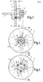
- FIGS. 3, 4 and 5 show a modification of the disc rotor 1 according to the embodiment of FIGS. 1 and 2.
- six ribs 8 are provided here for connecting the disk-shaped carrier 5 of the rotor 1 to the hub 7, which again run essentially radially and axially and the rotor 1 with the spacing in the axial direction connect in the lying hub 7 in the axial direction.
- the ribs 8 are arranged centrally symmetrically, with two adjacent ribs having a smaller distance from one another than the other adjacent ribs, as seen in the circumferential direction of the hub 7, which serves to additionally arrange one of three vibration absorbers 13 in each of the enlarged spaces thus formed to be able to.
- Each of these vibration absorbers which effect damping in a known manner, consists of a hollow cylindrical rubber buffer 14, which is inserted into a cylindrical recess 15 provided on the carrier 5 and into which a pin 16 protrudes, each of which is provided on the hub 7 Approach 17 cantilevered.
- the rubber buffers 14 elastic connecting elements, which are effective between the carrier 5 of the rotor 1 and the hub 7, in addition to the ribs 8, which also represent elastic connecting elements.
- these two types of elastic connecting elements are different, namely in that the ribs 8 cause a suspension with respect to the rotating drive movement, whereas the vibration absorbers cause damping.
- the measures in question can advantageously also be used to reduce disruptive influences which are introduced into the entire system by the load driven by the motor shaft and by a control device for the motor, so that overall a very stable one System is maintained.
- FIG. 6 shows an application example for a disc rotor motor using a disc rotor as shown in FIGS. 3 to 5.
- It is a scanning device of a recording and / or reproducing device for a tape-shaped recording medium, on which inclined tracks are scanned with rotatingly driven magnetic heads.
- a scanning unit consists of a stationary drum part 18 and a rotatingly drivable drum part 19 arranged coaxially therewith.
- a gap 20 is formed between these two drum parts 18 and 19, in which magnetic heads 21 arranged on the drum part 19 lie, whereby they are slightly protrude beyond the lateral surface of the two drum parts 18, 19, so that they are in operative connection with the recording medium which is helically guided over the lateral surface of the two drum parts 18, 19.
- the two drum parts are expediently designed together with the drive motor as one structural unit.
- the stationary drum part 18 is integrally formed on a housing part 22 of the disc rotor motor, this housing part 22 also carrying two bearings 23 and 24 for the motor shaft 4, to the free end of which the rotatingly drivable drum part 19 is fastened.
- An annular plate 25 again forms a magnetic inference for the magnetic fields generated by the magnetic ring 10.
- the coils seated in the carrier 5 are fed via lines (not shown) from a collector 26, which is also seated on the motor shaft 4 and to which the signals required to excite the coils of the rotor 1 are fed via sliding contacts 27.
- a control circuit formed by a servo system not shown here, is provided for obtaining the electrical signals to be supplied to the rotor of the rotor, into which the output signal of a tachometer generator is fed, which is fed by the Motor shaft 4 is driven forth, whereby its output signal is a measure of the current peripheral speed of the motor shaft 4.
- a disk 29 is provided on its periphery with a toothing 28 which is fastened to the hub 7, as a result of which it acts as a rotor for the tachometer generator.
- the toothing 28 of this disk 29 is opposed by a toothing 30 of a ring 31 arranged on the housing side, which together with a further housing part 32 serves for the magnetic inference of an axially extending magnetic field originating from a magnetic ring 33, which in this way forms a between the ring 31 and the housing part 32 arranged annular coil 34 passes through, which then delivers the output signal of the tachometer generator.
- the parts rotating together with the motor shaft 4 consist of the disc rotor 1, the hub 7, the disc 29 forming the rotor of the tachometer generator and the drum part 19 which represents the actual load, and the collector 26, the influence of which is neglected here, however can.
- Each of these parts represents a certain centrifugal mass, the centrifugal masses of the hub 7 and the disk 29 being counted as a centrifugal mass, since the disk 29 is attached directly to the hub 7.
- This common flywheel is one on the one hand via the motor shaft 4 with the flywheel mass of the drum part 19 and on the other hand via the elastic connecting elements 8 and 13 with the flywheel mass of the disc rotor 1, whereby an oscillation system with very specific properties is present.
- a mechanical vibration model can be specified for such a vibration system, as shown in FIG. 7.
- the flywheel mass of the drum part 19 is indicated by the rectangle 35
- the common flywheel mass of the hub 7 and the disk 29 connected to it is indicated by the rectangle 36
- the flywheel mass of the disk rotor 1 is indicated by the rectangle 37.
- the rectangle 38 symbolizes the coupling of the hub 7 and the disk 29 via the motor shaft 4 to the Trommeiteit 19
- the rectangle 39 the resilient coupling of the disk rotor 1 via the ribs 8 and the piston representation 40 the damping coupling of the disk rotor 1 via the vibration absorbers 13 the hub 7 and the disk 29.
- the thickness of the rectangles 38 and 39 makes the different degrees of resilient couplings clear, in that the motor shaft 4 forms a relatively rigid coupling, whereas the ribs 8 effect a soft resilient coupling.
- the vibration behavior of such a system can be described in a known manner using frequency diagrams. 8 shows frequency diagrams in this regard, the frequency being plotted on the abscissa on a logarithmic scale and the quotient of the angular frequency of the flywheel 34, that is to say the drum part 19, and the torque of the flywheel 37, that is to say the disk rotor 1, plotted on the ordinate on a logarithmic scale is.
- such a frequency response diagram reflects the state that the servo system feeding the coils of the disc rotor 1 sees from the entire vibration system.
- the disc rotor 1 is rigidly connected to the hub 7, that is to say no ribs 8 or vibration absorbers 13 are provided between these two parts, but a rigid connection.
- a rigid connection is indicated in the vibration model according to FIG. 7 by the dashed rectangle 41 lying between the flywheels 36 and 37.
- the relevant frequency diagram is indicated in FIG. 10 by a dashed line.
- such a vibration system has a pronounced resonance indicated by the arrow 42, which results from the interaction on the one hand of the sum of the two flywheels 36 and 37, i.e.
- the resonance 44 results from the interaction on the one hand of the flywheel 37, that is to say the disc rotor 1, and on the other hand the sum of the two flywheels 35 and 36, that is to say the drum part 19, the hub 7 and the disk 29 connected to this.
- the other resonance 45 results from the interaction of, on the one hand, the flywheel 37, i.e. the disc rotor 1, and on the other hand the flywheel 36, i.e. the hub 7 with the disc 29.
- the resonance now 44 is lower in frequency than the original resonance 42 and the resonance 45 in a much higher frequency range. However, this means that there is no longer any resonance in the critical frequency range in which the original resonance 42 was located.
- the resonances 44 and 45 are no longer as pronounced as the original resonance 42. Both are reflected in an improvement in the stability of the system and bring about an evenly smooth running of the drum part 19 to be driven.
Landscapes
- Engineering & Computer Science (AREA)
- General Engineering & Computer Science (AREA)
- Power Engineering (AREA)
- Physics & Mathematics (AREA)
- Acoustics & Sound (AREA)
- Aviation & Aerospace Engineering (AREA)
- Mechanical Engineering (AREA)
- Connection Of Motors, Electrical Generators, Mechanical Devices, And The Like (AREA)
- Motor Or Generator Frames (AREA)
Applications Claiming Priority (2)
| Application Number | Priority Date | Filing Date | Title |
|---|---|---|---|
| AT3460/82 | 1982-09-15 | ||
| AT0346082A AT376849B (de) | 1982-09-15 | 1982-09-15 | Elektromotor |
Publications (2)
| Publication Number | Publication Date |
|---|---|
| EP0106383A1 EP0106383A1 (de) | 1984-04-25 |
| EP0106383B1 true EP0106383B1 (de) | 1986-12-10 |
Family
ID=3550832
Family Applications (1)
| Application Number | Title | Priority Date | Filing Date |
|---|---|---|---|
| EP83201307A Expired EP0106383B1 (de) | 1982-09-15 | 1983-09-13 | Elektromotor |
Country Status (9)
| Country | Link |
|---|---|
| US (1) | US4471248A (es) |
| EP (1) | EP0106383B1 (es) |
| JP (1) | JPS5967846A (es) |
| AT (1) | AT376849B (es) |
| BR (1) | BR8304927A (es) |
| CA (1) | CA1201747A (es) |
| DE (1) | DE3368355D1 (es) |
| DK (1) | DK412083A (es) |
| ES (1) | ES525560A0 (es) |
Families Citing this family (36)
| Publication number | Priority date | Publication date | Assignee | Title |
|---|---|---|---|---|
| JPS6096961U (ja) * | 1983-12-08 | 1985-07-02 | 株式会社三協精機製作所 | 小型モ−タ用のロ−タ |
| DE8526565U1 (es) * | 1985-09-17 | 1987-01-22 | Diehl Gmbh & Co, 8500 Nuernberg, De | |
| US5319844A (en) * | 1985-12-23 | 1994-06-14 | Unique Mobility, Inc. | Method of making an electromagnetic transducer |
| MX161230A (es) * | 1985-12-23 | 1990-08-24 | Unique Mobility Inc | Mejoras en transductor electromagnetico de peso ligero |
| DE3604245A1 (de) * | 1986-02-11 | 1987-08-13 | Thomson Brandt Gmbh | Mehrpoliger gleichstrommotor |
| JPH03273845A (ja) | 1990-01-17 | 1991-12-05 | Siegel:Kk | ステッピングモータにおける吸振構造 |
| US5402024A (en) * | 1992-04-06 | 1995-03-28 | Matsushita Electric Industrial Co., Ltd. | Rotor for a permanent-magnet motor |
| US5283469A (en) * | 1992-07-29 | 1994-02-01 | General Electric Company | Impact start assist for an electric motor |
| US5306123A (en) * | 1993-04-08 | 1994-04-26 | General Electric Company | Noise isolating rotor for air handler motor |
| US5491598A (en) * | 1994-05-06 | 1996-02-13 | Seagate Technology, Inc. | Rotary actuator vibration damper |
| US5481142A (en) * | 1994-07-01 | 1996-01-02 | Xerox Corporation | Tuned vibration absorbers for AC motors |
| US5704111A (en) * | 1995-05-24 | 1998-01-06 | General Electric Company | Method for making a rotor for an electric motor |
| EP0748027B1 (en) * | 1995-06-07 | 2006-09-06 | General Electric Company | Dynamoelectric machine and rotor construction thereof |
| US6388404B1 (en) * | 1996-01-03 | 2002-05-14 | Decotex 2000 Corporation | Remote controlled window treatment and/or lighting system |
| IT1289377B1 (it) * | 1996-05-22 | 1998-10-02 | Electrolux Zanussi Elettrodome | Dispositivo per il montaggio del motore in una macchina lavabiancheria |
| DE19631384C1 (de) * | 1996-08-02 | 1997-10-16 | Clouth Gummiwerke Ag | Elektrische Maschine in einem Antriebsstrang, z. B. eines Kraftfahrzeuges |
| KR100291213B1 (ko) * | 1999-08-10 | 2001-05-15 | 조성춘 | 소형 휠발전기 및 그를 구비한 발광 휠 및 그 제조방법 |
| DE19951026A1 (de) * | 1999-10-22 | 2001-04-26 | Volkswagen Ag | Verfahren zum Herstellen eines Rotors einer elektrischen Maschine und entsprechender Rotor |
| DE10113140A1 (de) * | 2001-03-17 | 2002-09-19 | Zf Lenksysteme Gmbh | Elektromechanische Lenkunterstützungseinrichtung für ein Fahrzeug |
| US6408502B1 (en) * | 2001-05-18 | 2002-06-25 | General Electric Company | Method for a resilient rotor core assembly |
| JP3621929B2 (ja) * | 2002-04-18 | 2005-02-23 | ファナック株式会社 | 電動機およびその製造方法 |
| JP4279508B2 (ja) * | 2002-05-08 | 2009-06-17 | 日本電産サーボ株式会社 | 防振モータの構造 |
| KR100469256B1 (ko) * | 2002-05-14 | 2005-02-02 | 엘지전자 주식회사 | 세탁기 구동부의 방진구조 |
| CA2547984A1 (en) * | 2005-05-27 | 2006-11-27 | A.O. Smith Corporation | Rotor core with spacers |
| US7709991B2 (en) * | 2005-12-08 | 2010-05-04 | A. O. Smith Corporation | Rotor assembly for an electric machine including a vibration damping member and method of manufacturing same |
| EP2026449B1 (en) * | 2007-08-16 | 2012-01-11 | Young-Chun Jeung | Rotor of brushless direct-current motor |
| US8193742B2 (en) | 2008-07-22 | 2012-06-05 | Hunter Douglas Inc. | Programmable motor for window coverings |
| US8307878B2 (en) | 2009-01-14 | 2012-11-13 | Hunter Douglas Inc. | Noise dampening motor drive system for retractable covering for architectural openings |
| DE102009017850A1 (de) * | 2009-04-17 | 2010-10-21 | Siemens Aktiengesellschaft | Läufer für eine elektrische Maschine |
| NL1039407C2 (en) | 2012-02-27 | 2013-08-28 | Hunter Douglas Ind Bv | Architectural covering having a drive mechanism for extending and retracting a covering member between opposite first and second end positions. |
| NO334163B1 (no) * | 2012-03-30 | 2013-12-23 | Techni Holding As | Torsjonskompensator |
| DE102012210775A1 (de) * | 2012-06-25 | 2014-01-02 | Robert Bosch Gmbh | Befestigungsvorrichtung für ein Ankerlamellenpaket |
| EP3157144B1 (en) * | 2014-06-16 | 2019-05-22 | Kubota Corporation | Parallel hybrid power transmission mechanism |
| US9966829B2 (en) | 2015-11-24 | 2018-05-08 | Lin Engineering, Inc. | Reduced-vibration stepper motor |
| CN108696020A (zh) * | 2018-06-14 | 2018-10-23 | 广东威灵电机制造有限公司 | 转子和具有其的电机 |
| US11831215B2 (en) * | 2021-05-06 | 2023-11-28 | Aac Microtech (Changzhou) Co., Ltd. | Linear vibration motor |
Citations (4)
| Publication number | Priority date | Publication date | Assignee | Title |
|---|---|---|---|---|
| DE253285C (es) * | ||||
| US1543849A (en) * | 1922-12-26 | 1925-06-30 | Hibbard Charles Truman | Flexible flywheel |
| DE1538933A1 (de) * | 1966-11-28 | 1970-03-12 | Licentia Gmbh | Laeufer fuer elektrische Motoren geringer Leistung |
| FR2499326A1 (fr) * | 1981-02-04 | 1982-08-06 | Advolotkin Nikolai | Rotor d'une machine electrique a grande vitesse |
Family Cites Families (10)
| Publication number | Priority date | Publication date | Assignee | Title |
|---|---|---|---|---|
| US2385369A (en) * | 1940-06-28 | 1945-09-25 | Master Electric Co | Shaft coupling |
| US2929944A (en) * | 1956-07-24 | 1960-03-22 | Gen Motors Corp | Dynamoelectric machine |
| DE1252785B (de) * | 1963-07-09 | 1967-10-26 | Licentia Gmbh | Federelement zur Isolierung der axialen und Drehschwingungen kleiner Elektromotoren in Tongeraeten |
| US3226579A (en) * | 1963-08-05 | 1965-12-28 | Mach Tronics Inc | Alternating current electric motor |
| DE1538923B2 (de) * | 1964-10-12 | 1972-10-19 | Licentia Patent Verwaltungs GmbH, 6000 Frankfurt | Elektrischer aussenlaeufermotor in tongeraetequalitaet |
| DE1291015B (de) * | 1964-10-12 | 1969-03-20 | Licentia Gmbh | Elektrischer Aussenlaeufer-Kleinstmotor in Tongeraetequalitaet |
| US3361914A (en) * | 1965-08-20 | 1968-01-02 | Licentia Gmbh | Plastic support for motors |
| US3512022A (en) * | 1968-02-21 | 1970-05-12 | Dictaphone Corp | Flywheel flutter filter |
| GB1216439A (en) * | 1968-09-14 | 1970-12-23 | Schwartz & Co G | Improvements in or relating to resilient couplings |
| US4035676A (en) * | 1975-06-18 | 1977-07-12 | Original Equipment Motors Inc. | Small electric motors |
-
1982
- 1982-09-15 AT AT0346082A patent/AT376849B/de not_active IP Right Cessation
-
1983
- 1983-09-01 US US06/528,376 patent/US4471248A/en not_active Expired - Fee Related
- 1983-09-09 CA CA000436365A patent/CA1201747A/en not_active Expired
- 1983-09-12 BR BR8304927A patent/BR8304927A/pt unknown
- 1983-09-12 JP JP58166831A patent/JPS5967846A/ja active Pending
- 1983-09-12 DK DK412083A patent/DK412083A/da not_active Application Discontinuation
- 1983-09-13 EP EP83201307A patent/EP0106383B1/de not_active Expired
- 1983-09-13 DE DE8383201307T patent/DE3368355D1/de not_active Expired
- 1983-09-13 ES ES525560A patent/ES525560A0/es active Granted
Patent Citations (4)
| Publication number | Priority date | Publication date | Assignee | Title |
|---|---|---|---|---|
| DE253285C (es) * | ||||
| US1543849A (en) * | 1922-12-26 | 1925-06-30 | Hibbard Charles Truman | Flexible flywheel |
| DE1538933A1 (de) * | 1966-11-28 | 1970-03-12 | Licentia Gmbh | Laeufer fuer elektrische Motoren geringer Leistung |
| FR2499326A1 (fr) * | 1981-02-04 | 1982-08-06 | Advolotkin Nikolai | Rotor d'une machine electrique a grande vitesse |
Also Published As
| Publication number | Publication date |
|---|---|
| ES8406009A1 (es) | 1984-06-16 |
| EP0106383A1 (de) | 1984-04-25 |
| BR8304927A (pt) | 1984-04-24 |
| AT376849B (de) | 1985-01-10 |
| DK412083D0 (da) | 1983-09-12 |
| DK412083A (da) | 1984-03-16 |
| CA1201747A (en) | 1986-03-11 |
| US4471248A (en) | 1984-09-11 |
| ES525560A0 (es) | 1984-06-16 |
| ATA346082A (de) | 1984-05-15 |
| DE3368355D1 (en) | 1987-01-22 |
| JPS5967846A (ja) | 1984-04-17 |
Similar Documents
| Publication | Publication Date | Title |
|---|---|---|
| EP0106383B1 (de) | Elektromotor | |
| EP0572441B1 (de) | Magnetlagerzelle | |
| DE2556924C2 (de) | Lagerloser Schwingmotor | |
| DE3039255C2 (es) | ||
| DE3233216C2 (de) | Elektromotor mit senkrechter Welle | |
| DE3808331C2 (es) | ||
| DE102006051018B3 (de) | Spindelmotor mit radialen und axialen Lagersystemen | |
| DE1158624B (de) | Schrittschaltmotor | |
| DE3918958A1 (de) | Spindelmotor | |
| EP0591351B1 (de) | Plattenspeicher | |
| DE3149943C2 (de) | Zweiphasenschrittmotor | |
| DE2738789A1 (de) | Mehrpoliger magnetlaeufermotor mit schrittschaltbetrieb | |
| DE2614853A1 (de) | Antriebssystem mit einem direktantrieb fuer einen plattenteller | |
| DE2741062A1 (de) | Anordnung zur magnetischen lagerung | |
| EP0164118A2 (de) | Antriebsanordnung mit kollektorlosem Gleichstrommotor | |
| DE3147102A1 (de) | Rotor fuer synchronmotoren | |
| DE2249648B2 (de) | Schrittmotor mit schwingungsdaempfung | |
| EP0444445A1 (de) | Dynamisch abgestimmter Kreisel | |
| DE19823630C2 (de) | Motorlager für schnelldrehende Kleinmotoren | |
| DE3403041C1 (de) | Einphasensynchronmotor mit einem zweipoligen dauermagnetischen Rotor | |
| DE3150890A1 (de) | Drehgeschwindigkeitssignalgeber | |
| DE7342874U (de) | Offen-End-Spinnvorrichtung | |
| DE4234596C2 (de) | Elektromagnetische Kupplung | |
| DE3205712A1 (de) | Magnetisch gelagertes schwungrad | |
| DE2527046A1 (de) | Daempfungseinrichtung fuer einen schrittmotor |
Legal Events
| Date | Code | Title | Description |
|---|---|---|---|
| PUAI | Public reference made under article 153(3) epc to a published international application that has entered the european phase |
Free format text: ORIGINAL CODE: 0009012 |
|
| AK | Designated contracting states |
Designated state(s): DE FR GB IT NL SE |
|
| 17P | Request for examination filed |
Effective date: 19840522 |
|
| GRAA | (expected) grant |
Free format text: ORIGINAL CODE: 0009210 |
|
| AK | Designated contracting states |
Kind code of ref document: B1 Designated state(s): DE FR GB IT NL SE |
|
| PG25 | Lapsed in a contracting state [announced via postgrant information from national office to epo] |
Ref country code: NL Effective date: 19861210 Ref country code: IT Free format text: LAPSE BECAUSE OF FAILURE TO SUBMIT A TRANSLATION OF THE DESCRIPTION OR TO PAY THE FEE WITHIN THE PRESCRIBED TIME-LIMIT;WARNING: LAPSES OF ITALIAN PATENTS WITH EFFECTIVE DATE BEFORE 2007 MAY HAVE OCCURRED AT ANY TIME BEFORE 2007. THE CORRECT EFFECTIVE DATE MAY BE DIFFERENT FROM THE ONE RECORDED. Effective date: 19861210 |
|
| PG25 | Lapsed in a contracting state [announced via postgrant information from national office to epo] |
Ref country code: SE Effective date: 19861231 |
|
| REF | Corresponds to: |
Ref document number: 3368355 Country of ref document: DE Date of ref document: 19870122 |
|
| ET | Fr: translation filed | ||
| NLV1 | Nl: lapsed or annulled due to failure to fulfill the requirements of art. 29p and 29m of the patents act | ||
| PLBE | No opposition filed within time limit |
Free format text: ORIGINAL CODE: 0009261 |
|
| STAA | Information on the status of an ep patent application or granted ep patent |
Free format text: STATUS: NO OPPOSITION FILED WITHIN TIME LIMIT |
|
| 26N | No opposition filed | ||
| PGFP | Annual fee paid to national office [announced via postgrant information from national office to epo] |
Ref country code: GB Payment date: 19900831 Year of fee payment: 8 |
|
| PGFP | Annual fee paid to national office [announced via postgrant information from national office to epo] |
Ref country code: FR Payment date: 19900920 Year of fee payment: 8 |
|
| PGFP | Annual fee paid to national office [announced via postgrant information from national office to epo] |
Ref country code: DE Payment date: 19901123 Year of fee payment: 8 |
|
| PG25 | Lapsed in a contracting state [announced via postgrant information from national office to epo] |
Ref country code: GB Effective date: 19910913 |
|
| GBPC | Gb: european patent ceased through non-payment of renewal fee | ||
| PG25 | Lapsed in a contracting state [announced via postgrant information from national office to epo] |
Ref country code: FR Effective date: 19920529 |
|
| PG25 | Lapsed in a contracting state [announced via postgrant information from national office to epo] |
Ref country code: DE Effective date: 19920602 |
|
| REG | Reference to a national code |
Ref country code: FR Ref legal event code: ST |