EP0104262A1 - Composite self-supporting slab - product - method - device - application - Google Patents
Composite self-supporting slab - product - method - device - application Download PDFInfo
- Publication number
- EP0104262A1 EP0104262A1 EP82107468A EP82107468A EP0104262A1 EP 0104262 A1 EP0104262 A1 EP 0104262A1 EP 82107468 A EP82107468 A EP 82107468A EP 82107468 A EP82107468 A EP 82107468A EP 0104262 A1 EP0104262 A1 EP 0104262A1
- Authority
- EP
- European Patent Office
- Prior art keywords
- building material
- building
- strip
- lattice girder
- formwork
- Prior art date
- Legal status (The legal status is an assumption and is not a legal conclusion. Google has not performed a legal analysis and makes no representation as to the accuracy of the status listed.)
- Granted
Links
Images
Classifications
-
- E—FIXED CONSTRUCTIONS
- E04—BUILDING
- E04B—GENERAL BUILDING CONSTRUCTIONS; WALLS, e.g. PARTITIONS; ROOFS; FLOORS; CEILINGS; INSULATION OR OTHER PROTECTION OF BUILDINGS
- E04B5/00—Floors; Floor construction with regard to insulation; Connections specially adapted therefor
- E04B5/16—Load-carrying floor structures wholly or partly cast or similarly formed in situ
- E04B5/17—Floor structures partly formed in situ
Abstract
Description
Die Erfindung betrifft selbsttragende Bauplatten, die zur freien überbrückung von Räumen und öffnungen verwendet werden können und zum Bau von Decken, Wänden, Dächern, Fachwerkträgern, Behältern, Brücken und zu anderen Bauzwecken verwendbar sind.The invention relates to self-supporting building boards that can be used for free bridging rooms and openings and can be used for the construction of ceilings, walls, roofs, trusses, containers, bridges and for other construction purposes.
Insbesondere zur Verwendung als Raumdecken sind Hohlplatten bekannt, die gewöhnlich aus Stahlbeton bestehen und im Inneren Hohlräume besitzen. Diese Hohlplatten können ohne Zwischenunterstützung montiert werden, müssen aber in vorgefertigtem Zustand zur Baustelle transportiert werden, was infolge des hohen Cewichtes solcher Hohlplatten beim Antransport und der Montage Probleme ergibt. Außerdem lassen sich solche Hohlplatten lediglich an ihren Enden durch Ausgießen mit Beton verbinden, und diese Verbindungsstellen ergeben "gelenkartige" Schwachstellen.In particular, for use as ceilings, hollow panels are known, which usually consist of reinforced concrete and have cavities inside. These hollow panels can be assembled without intermediate support, but must be transported to the construction site in a prefabricated state, which results in problems due to the high weight of such hollow panels during transport and assembly. In addition, such hollow panels can only be connected at their ends by pouring concrete, and these connection points result in "joint-like" weak points.
Es sind zur freien überbrückung von Räumen auch bereits Rippenplatten bekannt, die gewissermaßen eine verlorene Schalung darstellen, die an der Baustelle mit Beton ausgegossen wird. Derartige Rippenplatten ergeben beim Ausgießen mit Beton eine vorteilhafte Einheit, doch bedürfen sie bei der Montage einer Zwischenunterstützung mit einem Leergerüst. Das gleiche gilt für einfache Platten mit eingegossenen Gitterträgern in Tragerichtung, die ebenfalls an Ort ausgegossen werden.For free bridging of rooms, ribbed slabs are already known, which to a certain extent represent lost formwork that is poured with concrete at the construction site. Such ribbed plates result in an advantageous unit when poured with concrete, but they require an intermediate support with an empty scaffold during assembly. The same applies to simple panels with cast-in lattice girders in the direction of wear, which are also poured out on site.
Die der Erfindung zugrundeliegende Aufgabe bestand nun darin, selbsttragende Bauplatten zu bekommen, die die Nachteile beider oben beschriebenen Bauplattentypen vermeiden und an Ort und Stelle ausgegossen werden können, ohne aber bei der Montage einer Zwischenunterstützung durch ein Leergerüstzu bedürfen.The underlying the invention task was to obtain self-supporting structural panels, which avoid the disadvantages of both Bauplattentypen described above and can be poured in place, but without requiring through an empty frame in the assembly of an intermediate support.
Diese Aufgabe wird erfinUngsgemäß mit einer aufgelösten selbsttragenden Bauplatte gelöst, die dadurch gekennzeichnet ist, daß sie aus einer Baustoffplatte und wenigstens einem über einen Gitterträger.und wenigstens ein Halterungsteil mit ihr verbundenen Baustoffstreifen besteht, wobei der Gitterträger entlang dem Baustoffstreifen angeordnet und an diesem und an der Baustoffplatte befestigt ist und wobei das Halterungsteil eine einseitig offene Ausnehmung aufweist, durch die hindurch der Gitterträger verläuft, und an dem Baustreifenstreifen und der Baustoffplatte befestigt ist.This object is achieved in accordance with the invention with a disassembled self-supporting building board, which is characterized in that it consists of a building material board and at least one building material strip connected to it via a lattice girder and at least one holding part, the lattice girder being arranged along the building material strip and on and against it the building material plate is fastened and wherein the holding part has a recess open on one side, through which the lattice girder runs, and is fastened to the building strip strip and the building material plate.
Diese erfindungsgemäßen aufgelösten selbsttragenden Bauplatten können überraschenderweise ohne Zwischenunterstützung montiert und ausgegossen werden, wobei sie entweder als Raumflächentafeln an die Raumdeckengröße angepaßt oder als Streifentafeln verwendbar sind. Im Regelfall werden diese Bauplatten mehrere Baustoffstreifen aufweisen, die in Tragerichtung verlaufen. Zwischen den Baustoffstreifen werden zur Erzeugung von Hohlplatten verlorene Schalungen eingelegt, die die Hohlräume ergeben.These dissolved self-supporting building boards according to the invention can surprisingly be assembled and poured out without intermediate support, they either being adapted to the size of the ceiling or as strip boards. As a rule, these building boards will have several strips of building material that run in the direction of wear. Formwork lost to produce hollow panels is inserted between the building material strips, resulting in the cavities.
Die erfindungsgemäßen Bauplatten haben weiterhin den Vorteil, daß sie mit der Außenfläche der Baustoffplatte direkt eine Raumdecke ergeben, die putzfähig ist, daß also keine zusätzlichen abgehängten Decken erforderlich sind. Außerdem ergeben die erfindungsgemäßen Bauplatten beim Ausgießen unmittelbar die endgültige Deckendicke.The building boards according to the invention also have the advantage that they directly form a ceiling with the outer surface of the building material board, which can be cleaned, so that no additional suspended ceilings are required. In addition, the building boards according to the invention immediately result in the final ceiling thickness when pouring.
Die Halterungsteile dienen gleichzeitig mit der Abstandshaltung zwischen der Baustoffplatte und den Baustoffstreifen eineYAufnahme zusätzlicher Schubkräfte. Die Halterungsteile können zur Erhöhung der Tragfähigkeit auch"zusätzlich noch eine Bewehrung enthalten.The holding parts serve, at the same time as the spacing between the building material plate and the building material strips, to absorb additional thrust forces. The bracket parts can also "additionally contain reinforcement to increase the load capacity.
Die Halterungsteile können unterschiedlich geformt sein, doch müssen sie eine einseitig offene Ausnehmung haben, um die Gitterträger einzufügen. In der Endlage müssen also die Halterungsteile die Gitterträger umgreifen. Die Ausnehmungen in den Halterungsteilen können unterschiedlich ausgebildet sein, wie beispielsweise kreisförmig mit einer seitlichen öffnung, doch ist eine zweckmäßige Ausbildung des Halterungsteils diejenigen mit im wesentlichen U-förmigem Querschnitt.The bracket parts can be shaped differently, but they must have a recess open on one side in order to insert the lattice girders. In the end position, the bracket parts must grip around the lattice girders. The recesses in the holder parts can be designed differently, such as, for example, circularly with a lateral opening, but an expedient design of the holder part is that with an essentially U-shaped cross section.
Das Baustoffmaterial der Bauplatte wie auch der Baustoffstreifen besteht im Regelfall aus Stahlbeton, so daß auch die Halterungsteile zweckmäßig aus Beton und bevorzugt aus Beton-U-Steinen bestehen.The building material of the building board as well as the building material strip is usually made of reinforced concrete, so that the bracket parts are suitably made of concrete and preferably of concrete U-stones.
Als Gitterträger können alle bekannten Gitterträger verwendet werden, und diese besitzen im wesentlichen dreieckigen Querschnitt mit einer nach dem Einbau entlang dem Betonstreifen angeordneten Stange am Scheitel der Winkelschenkel sowie zwei hierzu im wesentlichen parallelen Stangen, die die freien Kanten bilden.All known lattice girders can be used as lattice girders, and these have an essentially triangular cross-section with a rod arranged after installation along the concrete strip at the apex of the angle legs and two essentially parallel rods which form the free edges.
Die Stange am Scheitel des Gitterträgers kann nun entweder an der Baustoffplatte oder an einem Baustoffstreifen befestigt werden. Bevorzugt wird der Gitterträger mit den an seinen beiden freien Kanten liegenden Stangen an dem Baustoffstreifen und mit der Stange an seinem Scheitel an der Baustoffplatte befestigt.The rod at the top of the lattice girder can now be attached either to the building material panel or to a building material strip. The lattice girder is preferably fastened to the building material strip with the rods lying at its two free edges and with the rod at its apex to the building material plate.
Da, wie oben erwähnt, die Baustoffstreifen und die Baustoffplatte im Regelfall aus bewehrtem Beton bestehen, wird der Gitterträger an diesen Teilen so befestigt, daß seine freien Kanten bzw. sein Scheitel zusammen mit der Bewehrung der Baustoffplatte bzw. der Baustoffstreifen in deren Beton eingegossen werden.Since, as mentioned above, the building material strips and the building material plate usually consist of reinforced concrete, the lattice girder is attached to these parts in such a way that its free edges or apex are poured into the concrete together with the reinforcement of the building material plate or the building material strips .
Weiterhin ist es zweckmäßig, den Scheitel des Gitterträgers an der Bewehrung desjenigen Teils zu befestigen, in das der Scheitel des Gitterträgers eingegossen wird. Diese Befestigung erfolg zweckmäßig mit Hilfe einer im wesentlichen S-förmigen Halteklammer, deren die beiden Endteile verbindender Steg gebogen ausgebildet ist.Furthermore, it is expedient to fasten the apex of the lattice girder to the reinforcement of the part into which the apex of the lattice girder is cast. This attachment is expediently carried out with the aid of an essentially S-shaped retaining clip, the web connecting the two end parts of which is curved.
Bei der Montage der erfindungsgemäßen Bauplatten und zwar als Deckenplatte wird diese auf die fertiggestellten Wände aufgelegt, wonach in die Räume zwischen die Gitterträger beliebig geformte verlorene Schalungen für die Hohlräume eingelegt werden. Darüber kann zwischen die Baustoffstreifen eine weitere Bewehrung eingelegt werden, wonach dann bis zur Höhe der Außenflächen der Baustoffstreifen mit Beton ausgegossen wird.When assembling the building panels according to the invention, namely as a ceiling panel, this is placed on the finished walls, after which any form of lost formwork for the cavities is inserted between the lattice girders. In addition, another reinforcement can be inserted between the building material strips, after which the building material strips are then poured with concrete up to the height of the outer surfaces.
Die Verbindung mehrerer solcher Bauplatten am Ende der Baustoffstreifen erfolgt in gleicher Weise durch Ausgießen mit Beton, wobei hier ebenfalls Bewehrungen eingelegt werden können und/oder die Bewehrungen der Baustoffplatte und der Baustoffstreifen an deren Enden herausragen können und so die Verbindung zwischen diesen Enden und dem ausgegossenen Bereich zwischen zwei benachbarten Bauplatten herstellen. Zur Erleichterung des Ausgießens des Bereiches zwischen zwei aufeinander stoßenden Bauplatten, ist es zweckmäßig, wenn die Baustoffstreifen kürzer als die Baustoffplatte in Tragerichtung gehalten werden.The connection of several such building boards at the end of the building material strips is carried out in the same way by pouring with concrete, whereby reinforcements can also be inserted here and / or the reinforcements of the building material plate and the building material strips can protrude at their ends and thus the connection between these ends and the poured-out one Create an area between two adjacent building boards. To facilitate the pouring out of the area between two abutting building boards, it is expedient if the building material strips are kept shorter than the building material board in the direction of wear.
Die Herstellung der erfindungsgemäßen Bauplatten kann zweckmäßig auf folgende Weise erfolgen. Zunächst wird die Schalung für die Baustoffstreifen in der erforderlichen Zahl hergestellt und in diese Schalungen die Bewehrung der Baustoffstreifen oder der jedem Baustoffstreifen zugeordnete Gitterträger mit seinen beiden freien Kanten, d.h. mit seinem Scheitel nach oben, eingelegt. Außerdem werden die Halterungsteile so eingelegt, daß sie den jeweiligen Gitterträger umgreifen. Wenn es sich bei den Halterungsteilen zweckmäßig um U-Steine handelt, werden diese so in die Schalung für die Baustoffstreifen eingelegt, daß sie mit den freien Schenkeln in der Schalung stehen.The construction boards according to the invention can expediently be produced in the following manner. First the formwork for the building material strips is produced in the required number and the reinforcement of the building material strips or the lattice girder assigned to each building material strip with its two free edges, ie with its apex facing upwards, is inserted into these formworks. In addition, the bracket parts are inserted so that they encompass the respective lattice girder. If it’s the stops tion parts expediently U-stones, they are inserted into the formwork for the strips of building material that they stand with the free legs in the formwork.
Sodann wird diese Schalung mit dem Baustoffmaterial, gewöhnlich Beton, gefüllt und dieser ausgehärtet. Nunmehr werden die Baustoffstreifen mit den darin einbetonierten Bewehrungen, Gitterträgern und Halterungsteilen aus den Schalungen entfernt und um 180° gedreht. Sodann wird die Schalung für die Baustoffplatte i: der erwünschten Größe angefertigt, und die erwünschte Zahl von Baustoffstreifen wird mit nach unten weisenden Halterungsteilen und Gitterträgern im Abstand voneinander in diese Schalung der Baustoffplatte eingelegt. Schließlich wird das Baustoffmate rial, vorzugsweise Beton, der Baustoffplatte in diese Schalung eingefüllt und ausgehärtet. Nach der Entfernung aus der Schalun ist die erfindungsgemäße Bauplatte dann gebrauchsfertig.This formwork is then filled with the building material, usually concrete, and cured. Now the strips of building material with the reinforcement, lattice girders and mounting parts embedded in them are removed from the formwork and rotated by 180 °. Then the formwork for the building material panel i: of the desired size is made, and the desired number of building material strips is inserted into this formwork of the building material panel with the support parts and lattice girders pointing downwards. Finally, the building material, preferably concrete, of the building material plate is filled into this formwork and cured. After removal from the formwork, the building board according to the invention is then ready for use.
Um die Verbindung zwischen der Bewehrung der in der zweiten Stufe zu gießenden Baustoffplatte mit dem Gitterträger während d Herstellung zu erhöhen, ist es zweckmäßig, den Scheitel des Git. terträgers mit der Baustoffplatten-Bewehrung mit Hilfe von im wesentlichen S-förmigen Halteklammern mit gebogenem Steg zu verbinden. Der Steg dieser Halteklammern ist der Abschnitt, der zwi schen den Krümmungen in den Endabschnitten der insgesamt S- ode Z-förmigen Klammern liegt.In order to increase the connection between the reinforcement of the building material slab to be cast in the second stage with the lattice girder during manufacture, it is expedient to top the lattice girder with the building material slab reinforcement using essentially S-shaped retaining clips with a curved web connect to. The web of these retaining clips is the section that lies between the curvatures in the end sections of the overall S or Z-shaped clips.
Insbesondere, wenn die Halterungsteile einen relativ großen Abstand von den freien Enden der Baustoffstreifen haben, ist es zweckmäßig,bei der Herstellung der erfindungsgemäßen Bauplatten während des Einfüllens und Erhärtens des Baustoffmaterials der Baustoffplatte Abstandshalter zu verwenden, die die Baustoffstreifen an ihren Enden in dem gewünschten Abstand von der zu gießenden Baustoffplatte halten. Eine zweckmäßige Ausführungsform eines solchen Abstandshalters besteht aus einem senkrechten Stab mit einer Standeinrichtung am einen Ende, einem Anschlag für die Außenfläche des Baustoffstreifens am anderen Ende und einem auf dem Stab verschiebbaren Knebel. Dieser Knebel kann mit wenigen Schlägen entlang dem senkrechten Stab nach oben bis in Anlage an den Baustoffstreifen geschlagen werden, so daß dessen freies Ende zwischen dem Anschlag und dem Knebel festgelegt ist.In particular, if the mounting parts are at a relatively large distance from the free ends of the building material strips, it is expedient to use spacers in the production of the building boards according to the invention during the filling and hardening of the building material material of the building material plate, which ends of the building material strips are at the desired distance hold of the building material slab to be cast. An expedient embodiment of such a spacer consists of a vertical rod with a standing device at one end, a stop for the outer surface of the strip of building material at the other end and a toggle which can be displaced on the rod. This gag can be struck with a few strokes along the vertical rod up to the building material strip so that its free end is fixed between the stop and the gag.
Nach einer besonders bevorzugten Ausführungsform des erfindungsgemäßen Verfahrens verwendet man einen Abstandshalter, dessen Knebel aus einem den Stab umfassenden Teil besteht, dessen von dem Stab durchdrungene Ausnehmung zwei zueinander im wesentlichen parallele Innenwände besitzt, die nicht senkrecht sondern im Winkel zu der oberen Auflagefläche des Knebels für das Ende des Baustoffstreifens stehen. Die Innenwand des Knebels, die an der Seite des Stabes liegt, an der das Ende des Baustoffstreifens auf dem Knebel'aufliegt, schließt einen stumpfen Winkel mit der Auflagefläche des Knebels ein.According to a particularly preferred embodiment of the method according to the invention, a spacer is used, the gag of which consists of a part comprising the rod, the recess penetrated by the rod having two mutually substantially parallel inner walls, which are not perpendicular but at an angle to the upper contact surface of the gag for the end of the strip of building material. The inner wall of the gag, which lies on the side of the rod on which the end of the strip of building material rests on the gag, forms an obtuse angle with the contact surface of the gag.
Durch die Zeichnung wird die Erfindung weiter erläutert. In dieser bedeutet
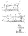
- Fig. 1 einen senkrechten Schnitt durch eine Bauplatte nach der Erfindung senkrecht zur Längsachse und damit zur Tragerichtung der Baustoffstreifen,
- Fig. 2 einen senkrechten Schnitt durch die gleiche Bauplatte wie in Fig. 1 mit am Ende angesetztem Abstandshalter für die Montage,
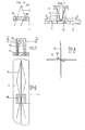
- Fig. 3 den in Fig.2 gezeigten Abstandshalter in Vorderansicht,
- Fig. 4 bis 7 verschiedene Phasen der Herstellung der in Fig. 1 gezeigten Baustoffplatte,
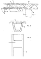
- Fig. 8 die Verbindung des Gitterträgers mit der Bewehrung der Baustoffplatte in Draufsicht und
- Fig. 9 eine Seitenansicht der Verbindungsstelle zweier Bauplattei nach der Erfindung.
- 1 is a vertical section through a building board according to the invention perpendicular to the longitudinal axis and thus to the direction of wear of the building material strips,
- 2 shows a vertical section through the same building board as in FIG. 1 with a spacer attached at the end for the assembly,
- 3 shows the spacer shown in FIG. 2 in a front view,
- 4 to 7 different phases of the production of the building material plate shown in Fig. 1,
- Fig. 8 shows the connection of the lattice girder with the reinforcement of the building material plate in plan view
- Fig. 9 is a side view of the junction of two building boards according to the invention.
Die in der Zeichnung dargestellte aufgelöste selbsttragende Bauplatte nach der Erfindung besteht aus einer Baustoffplatte 5 mit einer Bewehrung 4 und Baustoffstreifen 1 mit jeweils einer Bewehrung 2, wobei in Fig. 1 der Zeichnung nur zwei dieser Baustoff streifen 1 dargestellt sind. Weiterhin besteht die Bauplatt aus Halterungsteilen 12 in der Form von U-Steinen und Gitterträgern 3, wobei jedem Baustoffstreifen 1 ein Gitterträger 3 und mehrere Halterungsteile 12 zugeordnet sind.The resolved self-supporting building board shown in the drawing according to the invention consists of a
Gemäß den Figuren 4 bis 7, die die Herstellung der Bauplatte nach der Erfindung zeigen, wird zunächst der Gitterträger 3 mit seinen beiden freien Kanten 18 nach unten zusammen mit der Bewehrung 2 in die Schalung für den Baustoffstreifenl eingelegt (Fig.4).According to FIGS. 4 to 7, which show the production of the building board according to the invention, the
Sodann werden die Halterungsteile 12, die in der Zeichnung Wutenausbildungen 14 besitzen, mit der offenen Seite nach unten in bestimmten Abständen voneinander über den Gitterträger 3 gestülpt und in die Schalung des Baustoffstreifens 1 gestellt (Fig.5). Bei waagerechtem Schnitt durch Fig.5 entlang der Linie VI-VI ergibt sich das in Fig. 6 gezeigte Bild, das darstellt, daß die U-Steine über den Gitterträger 3 an deren engsten Stellen gestülpt werden.Then the
Nach dem Gießen des Baustoffstreifens 1 in der so vorbereiteten Schalung und nach Entfernung der Schalung wird der Baustoffstreifen mit einbetoniertem Gitterträger und einbetonierten Halterungsteilen um 180° gedreht und auf die Bewehrung 4 in der Schalung der Baustoffplatte 5 gesetzt, wie in Fig.7 gezeigt ist. Mit Hilfe einer S- bzw. Z-förmigen Klammer 13 mit gebogenem Steg wird der Scheitel 19 des Gitterträgers 3 mit der Bewehrung 4 der Baustoffplatte 5 verbunden, wie am besten aus Fig. 8 ersichtlich ist.After the casting of the
In Fig. 9 ist dargestellt, wie die selbsttragenden Bauplatten nach der Erfindung über Mörtelverbindungen 17 auf Wände 16 aufgelegt und im Bereich der Bezugsziffer 15 miteinander verbunden werden. Dabei ist es zweckmäßig, daß die Baustoffstreifen 1 wie in Fig. 9 gezeigt ist, kürzer als die Baustoffplatte 5 ist und daß an den Enden der Baustoffplatte 5 und der Baustoffstreifen 1 deren Bewehrung herausragt.FIG. 9 shows how the self-supporting building boards according to the invention are placed on
Während der Herstellung der erfindungsgemäßen Bauplatten wird zweckmäßig der in den Figuren 2 und 3 gezeigte Abstandshalter verwendet, der aus einem Stab 6 mit einer Standeinrichtung 8 und einem oberen Anschlag 7 sowie einem verschieblich gelagerten Knebel 9 besteht. Dieser besitzt eine Durchgangsöffnung, durch di der Stab 6 hindurchgeht,und die Innenseiten dieser öffnung stehe in einem Winkel (α) zu der Auflagefläche für das Ende der Baustoffstreifens 1, wobei jene Innenseite der Ausnehmung, die im Bereich des Endes des Baustoffstreifens liegt, mit der Auflagefläche einen stumpfen Winkelα einschließt. Die gegenüberliegende Innenseite der Ausnehmung ist hierzu parallel, so daß unter dem Druck des aufliegenden Endes des Baustoffstreifens sich der Knebel an der Stange 6 verkeilt, aber durch ein oder mehrere Hammerschläge auf das äußere obere Ende leicht wieder gelöst werden kann.During the manufacture of the building boards according to the invention, the spacer shown in FIGS. 2 and 3 is expediently used, which consists of a
Claims (12)
Priority Applications (3)
| Application Number | Priority Date | Filing Date | Title |
|---|---|---|---|
| DE8282107468T DE3271371D1 (en) | 1982-08-17 | 1982-08-17 | Composite self-supporting slab - product - method - device - application |
| AT82107468T ATE20106T1 (en) | 1982-08-17 | 1982-08-17 | DISSOLVED SELF-SUPPORTING PLATE - PRODUCT - PROCESS - DEVICE - USE. |
| EP82107468A EP0104262B1 (en) | 1982-08-17 | 1982-08-17 | Composite self-supporting slab - product - method - device - application |
Applications Claiming Priority (1)
| Application Number | Priority Date | Filing Date | Title |
|---|---|---|---|
| EP82107468A EP0104262B1 (en) | 1982-08-17 | 1982-08-17 | Composite self-supporting slab - product - method - device - application |
Publications (2)
| Publication Number | Publication Date |
|---|---|
| EP0104262A1 true EP0104262A1 (en) | 1984-04-04 |
| EP0104262B1 EP0104262B1 (en) | 1986-05-28 |
Family
ID=8189181
Family Applications (1)
| Application Number | Title | Priority Date | Filing Date |
|---|---|---|---|
| EP82107468A Expired EP0104262B1 (en) | 1982-08-17 | 1982-08-17 | Composite self-supporting slab - product - method - device - application |
Country Status (3)
| Country | Link |
|---|---|
| EP (1) | EP0104262B1 (en) |
| AT (1) | ATE20106T1 (en) |
| DE (1) | DE3271371D1 (en) |
Cited By (4)
| Publication number | Priority date | Publication date | Assignee | Title |
|---|---|---|---|---|
| WO1991002859A1 (en) * | 1989-08-23 | 1991-03-07 | Anton Jan Roeterdink | Building method |
| WO1996014481A1 (en) * | 1994-11-02 | 1996-05-17 | Ackea Handelsbolag | Beam element as well as production and use thereof |
| DE19815328A1 (en) * | 1998-04-06 | 1999-10-07 | Werner Simon | Concrete ceiling element |
| CN112942656A (en) * | 2021-02-03 | 2021-06-11 | 山东莱芜建设集团有限公司 | PK plate construction process |
Citations (6)
| Publication number | Priority date | Publication date | Assignee | Title |
|---|---|---|---|---|
| FR468789A (en) * | 1914-02-21 | 1914-07-16 | Etienne Chenille | New system for the construction of inclined walls or hollow floors using reinforced concrete |
| FR566745A (en) * | 1923-05-26 | 1924-02-19 | Improvements in the construction of reinforced concrete floors | |
| US1729612A (en) * | 1926-10-13 | 1929-10-01 | Goldsmith Metal Lath Company | Concrete floor construction |
| DE1609571A1 (en) * | 1966-01-07 | 1970-03-26 | Ing Othmar Ainedter | Panel-shaped component and method for producing floor slabs with them |
| DE2421905A1 (en) * | 1974-05-07 | 1975-11-20 | August Nolte | Lattice-reinforced composite steel-concrete ceiling on sheathing - has lightweight block filling providing sound and heat insulation |
| DE2810303A1 (en) * | 1977-03-11 | 1978-09-14 | Enzo Lubian | Hollow reinforced concrete beam with ceiling part - has reinforced ribs with projecting loops holding grid for ceiling concrete |
-
1982
- 1982-08-17 DE DE8282107468T patent/DE3271371D1/en not_active Expired
- 1982-08-17 EP EP82107468A patent/EP0104262B1/en not_active Expired
- 1982-08-17 AT AT82107468T patent/ATE20106T1/en not_active IP Right Cessation
Patent Citations (6)
| Publication number | Priority date | Publication date | Assignee | Title |
|---|---|---|---|---|
| FR468789A (en) * | 1914-02-21 | 1914-07-16 | Etienne Chenille | New system for the construction of inclined walls or hollow floors using reinforced concrete |
| FR566745A (en) * | 1923-05-26 | 1924-02-19 | Improvements in the construction of reinforced concrete floors | |
| US1729612A (en) * | 1926-10-13 | 1929-10-01 | Goldsmith Metal Lath Company | Concrete floor construction |
| DE1609571A1 (en) * | 1966-01-07 | 1970-03-26 | Ing Othmar Ainedter | Panel-shaped component and method for producing floor slabs with them |
| DE2421905A1 (en) * | 1974-05-07 | 1975-11-20 | August Nolte | Lattice-reinforced composite steel-concrete ceiling on sheathing - has lightweight block filling providing sound and heat insulation |
| DE2810303A1 (en) * | 1977-03-11 | 1978-09-14 | Enzo Lubian | Hollow reinforced concrete beam with ceiling part - has reinforced ribs with projecting loops holding grid for ceiling concrete |
Cited By (4)
| Publication number | Priority date | Publication date | Assignee | Title |
|---|---|---|---|---|
| WO1991002859A1 (en) * | 1989-08-23 | 1991-03-07 | Anton Jan Roeterdink | Building method |
| WO1996014481A1 (en) * | 1994-11-02 | 1996-05-17 | Ackea Handelsbolag | Beam element as well as production and use thereof |
| DE19815328A1 (en) * | 1998-04-06 | 1999-10-07 | Werner Simon | Concrete ceiling element |
| CN112942656A (en) * | 2021-02-03 | 2021-06-11 | 山东莱芜建设集团有限公司 | PK plate construction process |
Also Published As
| Publication number | Publication date |
|---|---|
| EP0104262B1 (en) | 1986-05-28 |
| ATE20106T1 (en) | 1986-06-15 |
| DE3271371D1 (en) | 1986-07-03 |
Similar Documents
| Publication | Publication Date | Title |
|---|---|---|
| DE1903129C3 (en) | Device for connecting a beam to a concrete column | |
| DE3403537A1 (en) | Prefabricated balcony-construction element for buildings | |
| EP0752033B1 (en) | Structure consisting of prefabricated components | |
| EP0299226B1 (en) | Shuttering for making concrete building-elements | |
| EP0104262B1 (en) | Composite self-supporting slab - product - method - device - application | |
| DE3609780A1 (en) | Prefabricated shuttering element | |
| AT407411B (en) | REINFORCEMENT BODY FOR A ROCK Ceiling made of cast concrete | |
| DE19941603C2 (en) | Reinforced concrete part for the production of foundations for buildings | |
| DE1299838B (en) | Prefabricated assembly skeleton construction made of prestressed concrete | |
| DE2802032A1 (en) | FLOOR OR BUILDING PLATE | |
| DE2636168C2 (en) | Buildings made from load-bearing prefabricated components | |
| DE1804657A1 (en) | Process for the production of concrete or reinforced concrete walls and concrete or reinforced concrete wall produced using this process | |
| DE2912131C2 (en) | garage | |
| DE1609855A1 (en) | Reinforcement element for flat building structures | |
| EP0698700B1 (en) | Floor construction and method for manufacturing the same | |
| DE807015C (en) | Reinforced concrete ceiling | |
| DE19720637C1 (en) | Process for producing a component from reinforced concrete and formwork for carrying out the process | |
| DE3933392A1 (en) | Self-supporting expandable constructional plate - has three=dimensional lattice work structure between bottom portion and strip | |
| AT10698U1 (en) | CONNECTING ELEMENT AND HOLLOWING ELEMENT WITH SUCH CONNECTING ELEMENTS | |
| AT408004B (en) | Prefabricated-concrete-wall shuttering-element system | |
| DE1229270B (en) | Reinforced concrete rib ceiling | |
| AT270962B (en) | Prefabricated, large-format, thin-walled reinforced concrete panel element | |
| DE1559530A1 (en) | Wall construction, especially reinforcement unit | |
| DE2121503A1 (en) | Enclosed building unit | |
| DE19611200A1 (en) | Reinforcement arrangement for aerated concrete components |
Legal Events
| Date | Code | Title | Description |
|---|---|---|---|
| PUAI | Public reference made under article 153(3) epc to a published international application that has entered the european phase |
Free format text: ORIGINAL CODE: 0009012 |
|
| 17P | Request for examination filed |
Effective date: 19820928 |
|
| AK | Designated contracting states |
Designated state(s): AT BE CH DE FR GB IT LI LU NL SE |
|
| GRAA | (expected) grant |
Free format text: ORIGINAL CODE: 0009210 |
|
| AK | Designated contracting states |
Kind code of ref document: B1 Designated state(s): AT BE CH DE FR GB IT LI LU NL SE |
|
| PG25 | Lapsed in a contracting state [announced via postgrant information from national office to epo] |
Ref country code: NL Effective date: 19860528 Ref country code: IT Free format text: LAPSE BECAUSE OF FAILURE TO SUBMIT A TRANSLATION OF THE DESCRIPTION OR TO PAY THE FEE WITHIN THE PRESCRIBED TIME-LIMIT;WARNING: LAPSES OF ITALIAN PATENTS WITH EFFECTIVE DATE BEFORE 2007 MAY HAVE OCCURRED AT ANY TIME BEFORE 2007. THE CORRECT EFFECTIVE DATE MAY BE DIFFERENT FROM THE ONE RECORDED. Effective date: 19860528 Ref country code: FR Free format text: THE PATENT HAS BEEN ANNULLED BY A DECISION OF A NATIONAL AUTHORITY Effective date: 19860528 Ref country code: BE Effective date: 19860528 |
|
| REF | Corresponds to: |
Ref document number: 20106 Country of ref document: AT Date of ref document: 19860615 Kind code of ref document: T |
|
| PG25 | Lapsed in a contracting state [announced via postgrant information from national office to epo] |
Ref country code: SE Effective date: 19860531 |
|
| REF | Corresponds to: |
Ref document number: 3271371 Country of ref document: DE Date of ref document: 19860703 |
|
| PG25 | Lapsed in a contracting state [announced via postgrant information from national office to epo] |
Ref country code: AT Effective date: 19860817 |
|
| PG25 | Lapsed in a contracting state [announced via postgrant information from national office to epo] |
Ref country code: LU Free format text: LAPSE BECAUSE OF NON-PAYMENT OF DUE FEES Effective date: 19860831 Ref country code: LI Effective date: 19860831 Ref country code: CH Effective date: 19860831 |
|
| EN | Fr: translation not filed | ||
| NLV1 | Nl: lapsed or annulled due to failure to fulfill the requirements of art. 29p and 29m of the patents act | ||
| PLBE | No opposition filed within time limit |
Free format text: ORIGINAL CODE: 0009261 |
|
| STAA | Information on the status of an ep patent application or granted ep patent |
Free format text: STATUS: NO OPPOSITION FILED WITHIN TIME LIMIT |
|
| REG | Reference to a national code |
Ref country code: CH Ref legal event code: PL |
|
| 26N | No opposition filed | ||
| PG25 | Lapsed in a contracting state [announced via postgrant information from national office to epo] |
Ref country code: GB Free format text: LAPSE BECAUSE OF NON-PAYMENT OF DUE FEES Effective date: 19881122 |
|
| PGFP | Annual fee paid to national office [announced via postgrant information from national office to epo] |
Ref country code: DE Payment date: 19980206 Year of fee payment: 16 |
|
| PG25 | Lapsed in a contracting state [announced via postgrant information from national office to epo] |
Ref country code: DE Free format text: LAPSE BECAUSE OF NON-PAYMENT OF DUE FEES Effective date: 19990601 |