EP0103771A1 - Testgasleckdetektor und Vorrichtung dazu, zum Messen und Anzeigen der Leckmenge Q - Google Patents
Testgasleckdetektor und Vorrichtung dazu, zum Messen und Anzeigen der Leckmenge Q Download PDFInfo
- Publication number
- EP0103771A1 EP0103771A1 EP83108295A EP83108295A EP0103771A1 EP 0103771 A1 EP0103771 A1 EP 0103771A1 EP 83108295 A EP83108295 A EP 83108295A EP 83108295 A EP83108295 A EP 83108295A EP 0103771 A1 EP0103771 A1 EP 0103771A1
- Authority
- EP
- European Patent Office
- Prior art keywords
- decades
- range
- leak
- valve
- analysis cell
- Prior art date
- Legal status (The legal status is an assumption and is not a legal conclusion. Google has not performed a legal analysis and makes no representation as to the accuracy of the status listed.)
- Granted
Links
Images

Classifications
-
- G—PHYSICS
- G01—MEASURING; TESTING
- G01D—MEASURING NOT SPECIALLY ADAPTED FOR A SPECIFIC VARIABLE; ARRANGEMENTS FOR MEASURING TWO OR MORE VARIABLES NOT COVERED IN A SINGLE OTHER SUBCLASS; TARIFF METERING APPARATUS; MEASURING OR TESTING NOT OTHERWISE PROVIDED FOR
- G01D13/00—Component parts of indicators for measuring arrangements not specially adapted for a specific variable
- G01D13/02—Scales; Dials
- G01D13/04—Construction
- G01D13/10—Construction with adjustable scales; with auxiliary scales, e.g. vernier
-
- G—PHYSICS
- G01—MEASURING; TESTING
- G01M—TESTING STATIC OR DYNAMIC BALANCE OF MACHINES OR STRUCTURES; TESTING OF STRUCTURES OR APPARATUS, NOT OTHERWISE PROVIDED FOR
- G01M3/00—Investigating fluid-tightness of structures
- G01M3/02—Investigating fluid-tightness of structures by using fluid or vacuum
- G01M3/04—Investigating fluid-tightness of structures by using fluid or vacuum by detecting the presence of fluid at the leakage point
- G01M3/20—Investigating fluid-tightness of structures by using fluid or vacuum by detecting the presence of fluid at the leakage point using special tracer materials, e.g. dye, fluorescent material, radioactive material
- G01M3/202—Investigating fluid-tightness of structures by using fluid or vacuum by detecting the presence of fluid at the leakage point using special tracer materials, e.g. dye, fluorescent material, radioactive material using mass spectrometer detection systems
Definitions
- a tracer gas such as helium which is injected into said organ or installation.
- the helium emerges from the latter and is sent to a measuring device such as a mass spectrometer gas analyzer which therefore allows according to the quantity of helium received to determine the importance of said crack.
- an analysis cell such as a mass spectrometer, a primary pump, for example a vane pump, a secondary pumping device of the turbo diffusion pump type -molecular or ionic, a trap for example with liquid nitrogen, and a pressure gauge.
- a third part capable of introducing the gaseous mixture to be analyzed or a fraction of the latter into said second part and generally comprising a valve with adjustable flow.
- the analysis cell detects a flow of helium q which passes through it, and which corresponds to all or part of the flow Q emerging from a crack in the organ or installation to be tested. .
- the measurement capacity of the electronic circuits associated with the analysis cell is limited to a limited number of n decades of leakage values, ie 5 to 6 at most.
- the present invention overcomes the drawbacks mentioned above by allowing the operator to know exactly the possibilities. of his device.
- the subject of the invention is a device for measuring and displaying the leakage rate Q for a tracer gas leak detector of the type mainly comprising a primary vacuum pump capable of being connected or not to a member to be controlled, a valve also connected to said member to be controlled and communicating with an analysis cell maintained under vacuum by means of a pumping group comprising a primary pump and a secondary pump, said valve comprising a valve whose degree of opening is controlled by a motor slaved to the pressure prevailing substantially at the input of said analysis cell, this degree of opening being converted into an electrical signal transmitted to said measurement and display device itself slaved to said analysis cell, characterized in that said measurement and display device comprises a signaling system making it possible to select and display a range of n decades in a range of N decades and to display simultaneously in this range of n decades the value of the leak of the organ to be checked.
- said signaling system simultaneously comprises a tape graduated over a range of N decades capable of scrolling past a window extending over a length corresponding to n decades, and an indicator hand.
- the signaling system comprises a light device indicating the selected portion of the n decades of work from the range of the N decades, and simultaneously indicating by light means the value of the leak in this selected range.
- the reference 1 is assigned to a member, for example a reservoir, the tightness of which must be checked.
- This reservoir is connected to a primary vane pump 2 via a line 3, a valve 17 being interposed on the line 3 for the purpose of possibly isolating the pump 2.
- a valve d air inlet 4 On this line 3 are connected a valve d air inlet 4 and a pressure gauge 5.
- Line 3 communicates via a line 6 with a valve 7 for introducing gas to the analysis cell, which will be more particularly described elsewhere.
- This valve 7 communicates by means of a pipe 8 with a liquid nitrogen trap 9 at which are connected an analysis cell 10 such as a mass spectrometer and a pressure gauge 11.
- a pipe 12 connects said trap 9 with a secondary pumping device 13 itself connected with a primary vane pump 14, and this by means of the pipe 15.
- the secondary pumping device 13 is a diffusion pump, a turbomolecular pump or an ion pump.
- Reference 16 designates an electronic device for calculating and displaying the results of detection measurements.
- valve 7 is of the motorized valve type, that is to say that it comprises a valve with progressive opening, the profile of which allows its implementation for pressures upstream of the order of 10 -4 to 1. mbar.
- the movement of said valve is controlled by an electric or pneumatic motor shown diagrammatically at 20 and controlled by the pressure of the pressure gauge 11, such functions being embodied by the dashed lines L 1 and L 2 respectively.
- the movement of the valve causes a concomitant movement of the cursor of a potentiometer (not shown) thereby transmitting to the electronic device 16 a signal representative of the degree of opening of the valve 7 such a function being materialized by the line L 3 .
- line L 4 shows that the electronic device 16 is also controlled by the analysis cell 10.
- said electronic device 16 receives information corresponding to the degree of opening or valve 7 closes.
- the information thus delivered makes it possible to move, by means of rollers 23, a ribbon 22 (FIG. 2) carrying a logarithmic graduation over a range of N decades, ranging for example from 10 -12 to 10 3 atmosphere. cm 3 / second, therefore corresponding to the limit performance of the detector.
- the numbers represented on the strip 22 constitute the different powers of ten.
- Said ribbon 22 scrolls past a reading window 24 which reveals only the number n of decades corresponding to the reading range possible under the operating conditions, ie 4 to 5 in the example shown. The operator is thus informed of the minimum and maximum values that he can measure under the operational conditions of the test.
- said window 24 includes a movable needle 25 whose position is controlled, by a potentiometric servo device, at the output of the analysis cell 10 via the device 16 therefore to the flow of helium q which passes through the cell, this flux being amplified by a logarithmic amplifier.
- This needle 25 therefore displays the exact value of the leak Q in the measurement range n appearing in window 24.
- the device according to the invention makes it possible to indicate to the operator, the exact value of the flow Q therefore of the leakage of the organ tested, as well as the range of measurement possible in a range of n decades selected from the N decades as defined in the above, and this whatever the inlet pressures of the gas flow.
- Such a device makes it possible to clarify the interpretation of the signals delivered by the analysis cell.
- tracer gas such as helium or hydrogen.
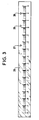
- FIG. 3 represents a possible variant of FIG. 2 in which the graduations of the N decades are inscribed on a fixed scale 26, and the range of possible measurement over a range of n decades, under the current conditions of measurement, is given by two mobile light signals 27 and 28 represented in the form of triangles in FIG. 3. And likewise, the mobile indicator needle 25 of the value of the leak in FIG. 2, is replaced in this variant of FIG. 3 by a mobile light signal 29 between signals 27 and 28 indicating the possible range of measurement. This mobile light signal 29 is also represented in the form of a triangle.
Applications Claiming Priority (2)
| Application Number | Priority Date | Filing Date | Title |
|---|---|---|---|
| FR8214699A FR2532424A1 (fr) | 1982-08-27 | 1982-08-27 | Dispositif de mesure et d'affichage du taux q de fuite pour un detecteur de fuites a gaz traceur |
| FR8214699 | 1982-08-27 |
Publications (2)
| Publication Number | Publication Date |
|---|---|
| EP0103771A1 true EP0103771A1 (de) | 1984-03-28 |
| EP0103771B1 EP0103771B1 (de) | 1987-09-09 |
Family
ID=9277082
Family Applications (1)
| Application Number | Title | Priority Date | Filing Date |
|---|---|---|---|
| EP83108295A Expired EP0103771B1 (de) | 1982-08-27 | 1983-08-23 | Testgasleckdetektor und Vorrichtung dazu, zum Messen und Anzeigen der Leckmenge Q |
Country Status (5)
| Country | Link |
|---|---|
| US (1) | US4510792A (de) |
| EP (1) | EP0103771B1 (de) |
| JP (1) | JPS5960238A (de) |
| DE (1) | DE3373536D1 (de) |
| FR (1) | FR2532424A1 (de) |
Families Citing this family (18)
| Publication number | Priority date | Publication date | Assignee | Title |
|---|---|---|---|---|
| FR2561771B1 (fr) * | 1984-03-23 | 1986-06-27 | Cit Alcatel | Procede pour depolluer un detecteur de fuite a helium et dispositif pour la mise en oeuvre du procede |
| US4735084A (en) * | 1985-10-01 | 1988-04-05 | Varian Associates, Inc. | Method and apparatus for gross leak detection |
| FR2604522B1 (fr) * | 1986-09-26 | 1989-06-16 | Cit Alcatel | Installation de detection de fuite a gaz traceur et procede d'utilisation |
| JP2507023Y2 (ja) * | 1990-05-26 | 1996-08-14 | 松下電工株式会社 | 出隅コ―ナ―役物の取付構造 |
| US5168747A (en) * | 1990-11-26 | 1992-12-08 | Westinghouse Electric Corp. | System and method for locating leaks in steam turbine systems |
| JPH0674855A (ja) * | 1992-07-08 | 1994-03-18 | Hitachi Bill Shisetsu Eng Kk | 真空漏洩検出方法、および同装置 |
| US5625141A (en) * | 1993-06-29 | 1997-04-29 | Varian Associates, Inc. | Sealed parts leak testing method and apparatus for helium spectrometer leak detection |
| DE4408877A1 (de) * | 1994-03-16 | 1995-09-21 | Leybold Ag | Testgaslecksucher |
| US5746435A (en) * | 1994-09-30 | 1998-05-05 | Arbuckle; Donald P. | Dual seal barrier fluid leakage control method |
| FI970665A0 (fi) | 1996-04-15 | 1997-02-17 | Espoon Paineilma Oy | Foerfarande foer identifiering av laeckage i en foerpackning isynnerhet livsmedels- och laekemedelsfoerpackning samt foerbaettrande av haollbarheten hos vaetskeformiga livsmedel vilka aer foerpackade i aseptiska kartongfoerpackningar |
| FR2761776B1 (fr) * | 1997-04-03 | 1999-07-23 | Alsthom Cge Alcatel | Detecteur de fuite a gaz traceur |
| DE19735250A1 (de) | 1997-08-14 | 1999-02-18 | Leybold Vakuum Gmbh | Verfahren zum Betrieb eines Heliumlecksuchers und für die Durchführung dieses Verfahrens geeigneter Heliumlecksucher |
| EP1104518B1 (de) * | 1998-08-17 | 2006-04-19 | Donald Philip Arbuckle | Integrierte abdichtungsschutzvorrichtung gegen flüssigkeiten mit visuellervolumenangabe |
| US6314793B1 (en) * | 1999-09-28 | 2001-11-13 | Gas Research Institute | Test device for measuring chemical emissions |
| US6885967B2 (en) * | 2003-06-23 | 2005-04-26 | Honeywell International Inc. | Spacecraft depressurization analyzer |
| US7764186B2 (en) * | 2007-04-23 | 2010-07-27 | J And N Enterprises Inc. | Gas sensing method and instrument therefor |
| KR101010674B1 (ko) * | 2008-08-28 | 2011-01-24 | 삼성전기주식회사 | 잉크 흡입 장치 |
| US11035818B2 (en) * | 2014-08-15 | 2021-06-15 | Roche Diabetes Care, Inc. | Blood glucose meter with low cost user interface having programmed graphic indicators |
Citations (5)
| Publication number | Priority date | Publication date | Assignee | Title |
|---|---|---|---|---|
| GB1054059A (de) * | 1962-11-14 | 1900-01-01 | ||
| FR1428585A (fr) * | 1965-01-06 | 1966-02-18 | Jaeger Ets Ed | Perfectionnement apporté aux instruments de mesure à échelles de lecture rectilignes |
| US3416359A (en) * | 1966-07-01 | 1968-12-17 | Texas Instruments Inc | Method and apparatus for testing hermetically sealed transistor devices |
| FR2313663A1 (fr) * | 1975-06-04 | 1976-12-31 | Portescap | Appareil de mesure a indication lineaire |
| DE2713580A1 (de) * | 1977-03-28 | 1978-10-05 | Leybold Heraeus Gmbh & Co Kg | Verfahren zum betrieb einer lecksucheinrichtung sowie dazu geeignete lecksucheinrichtung |
Family Cites Families (8)
| Publication number | Priority date | Publication date | Assignee | Title |
|---|---|---|---|---|
| GB1047204A (de) * | 1964-05-26 | 1900-01-01 | ||
| US3327521A (en) * | 1964-10-26 | 1967-06-27 | Nat Res Corp | Leak detector and vacuum pumping station |
| FR1474137A (fr) * | 1966-02-08 | 1967-03-24 | Alcatel Sa | Détecteur de fuites à l'hélium aisément transportable |
| US3690151A (en) * | 1968-07-25 | 1972-09-12 | Norton Co | Leak detector |
| US3626760A (en) * | 1969-07-16 | 1971-12-14 | Varian Associates | Leak detection cyclic pumping control |
| US3968675A (en) * | 1974-06-07 | 1976-07-13 | Varian Associates | Method and apparatus for preparing a mass spectrometer leak detector system for operation |
| JPS593790B2 (ja) * | 1975-06-20 | 1984-01-26 | 日本電気株式会社 | Fft エンサンシヨリソウチ |
| FR2475728A1 (fr) * | 1980-02-11 | 1981-08-14 | Cit Alcatel | Detecteur de fuites a helium |
-
1982
- 1982-08-27 FR FR8214699A patent/FR2532424A1/fr active Granted
-
1983
- 1983-08-23 EP EP83108295A patent/EP0103771B1/de not_active Expired
- 1983-08-23 DE DE8383108295T patent/DE3373536D1/de not_active Expired
- 1983-08-24 US US06/525,902 patent/US4510792A/en not_active Expired - Fee Related
- 1983-08-25 JP JP58155680A patent/JPS5960238A/ja active Granted
Patent Citations (5)
| Publication number | Priority date | Publication date | Assignee | Title |
|---|---|---|---|---|
| GB1054059A (de) * | 1962-11-14 | 1900-01-01 | ||
| FR1428585A (fr) * | 1965-01-06 | 1966-02-18 | Jaeger Ets Ed | Perfectionnement apporté aux instruments de mesure à échelles de lecture rectilignes |
| US3416359A (en) * | 1966-07-01 | 1968-12-17 | Texas Instruments Inc | Method and apparatus for testing hermetically sealed transistor devices |
| FR2313663A1 (fr) * | 1975-06-04 | 1976-12-31 | Portescap | Appareil de mesure a indication lineaire |
| DE2713580A1 (de) * | 1977-03-28 | 1978-10-05 | Leybold Heraeus Gmbh & Co Kg | Verfahren zum betrieb einer lecksucheinrichtung sowie dazu geeignete lecksucheinrichtung |
Also Published As
| Publication number | Publication date |
|---|---|
| FR2532424A1 (fr) | 1984-03-02 |
| FR2532424B1 (de) | 1984-12-28 |
| DE3373536D1 (en) | 1987-10-15 |
| JPH0263174B2 (de) | 1990-12-27 |
| EP0103771B1 (de) | 1987-09-09 |
| JPS5960238A (ja) | 1984-04-06 |
| US4510792A (en) | 1985-04-16 |
Similar Documents
| Publication | Publication Date | Title |
|---|---|---|
| EP0103771B1 (de) | Testgasleckdetektor und Vorrichtung dazu, zum Messen und Anzeigen der Leckmenge Q | |
| US9632067B2 (en) | Leak detector | |
| CA2434360C (en) | Product leak testing | |
| US6314793B1 (en) | Test device for measuring chemical emissions | |
| US3924442A (en) | Pollutant variation correcting system | |
| JP2635587B2 (ja) | リーク検査装置のディテクタを較正する装置 | |
| JPH10104037A (ja) | 排気ガス測定装置 | |
| JP2018533741A (ja) | 酸素を用いたリーク検知 | |
| EP0033945B1 (de) | Lecksuchvorrichtung mit Helium | |
| US3939695A (en) | Apparatus for detecting leaks | |
| FR2616226A1 (fr) | Dispositif de compensation d'humidite pour un detecteur de type photo-ionisation, et appareil pour sa mise en oeuvre | |
| US4348887A (en) | Apparatus for determining the effects of dilution and/or diffusion on the gaseous components of a gas flow | |
| CA1265357A (en) | Method and a device for detecting leakage of a tube section | |
| JP3166859B2 (ja) | 軽質のガスを用いたテストガス漏れ検査のための真空・漏れ検査装置 | |
| US11199467B2 (en) | Device and method for distinguishing a test gas escaping from a leak from interfering gas | |
| EP0070341B1 (de) | Heliumleckdetektor | |
| JP4447266B2 (ja) | 排ガス流量計測装置およびこれを用いた排ガス計測システム | |
| RU2778833C2 (ru) | Устройство и способ различения поверочного газа, выходящего из течи, от возмущающего газа | |
| US4100790A (en) | Electronic orsat for gas analysis | |
| US20230204447A1 (en) | Sniffing gas leak detector with hand probe | |
| JPH08254523A (ja) | 試料の酸素透過性を測定するための測定装置および方法 | |
| FR2522147A1 (fr) | Procede et dispositif pour detecter des fuites d'un melange gaz-air hors de circuits de fluide fermes | |
| SU858430A1 (ru) | Устройство дл калибровки несплошностей | |
| Park | Aids for the Analyst-Semimicro Gas Permeability Apparatus for Sheet Material | |
| SU257133A1 (ru) | УСТРОЙСТВО дл ИЗОКИНЕТИЧЕСКОГО ОТБОРА ПРОБ ПРОМЫШЛЕННЫХ АЭРОЗОЛЕЙ |
Legal Events
| Date | Code | Title | Description |
|---|---|---|---|
| PUAI | Public reference made under article 153(3) epc to a published international application that has entered the european phase |
Free format text: ORIGINAL CODE: 0009012 |
|
| AK | Designated contracting states |
Designated state(s): DE FR GB IT NL SE |
|
| 17P | Request for examination filed |
Effective date: 19840925 |
|
| 17Q | First examination report despatched |
Effective date: 19860124 |
|
| RAP1 | Party data changed (applicant data changed or rights of an application transferred) |
Owner name: ALCATEL |
|
| R17C | First examination report despatched (corrected) |
Effective date: 19860623 |
|
| RAP1 | Party data changed (applicant data changed or rights of an application transferred) |
Owner name: ALCATEL CIT |
|
| GRAA | (expected) grant |
Free format text: ORIGINAL CODE: 0009210 |
|
| AK | Designated contracting states |
Kind code of ref document: B1 Designated state(s): DE FR GB IT NL SE |
|
| REF | Corresponds to: |
Ref document number: 3373536 Country of ref document: DE Date of ref document: 19871015 |
|
| ITF | It: translation for a ep patent filed |
Owner name: JACOBACCI & PERANI S.P.A. |
|
| GBT | Gb: translation of ep patent filed (gb section 77(6)(a)/1977) | ||
| PLBE | No opposition filed within time limit |
Free format text: ORIGINAL CODE: 0009261 |
|
| STAA | Information on the status of an ep patent application or granted ep patent |
Free format text: STATUS: NO OPPOSITION FILED WITHIN TIME LIMIT |
|
| 26N | No opposition filed | ||
| PGFP | Annual fee paid to national office [announced via postgrant information from national office to epo] |
Ref country code: SE Payment date: 19910521 Year of fee payment: 9 |
|
| PGFP | Annual fee paid to national office [announced via postgrant information from national office to epo] |
Ref country code: FR Payment date: 19910530 Year of fee payment: 9 |
|
| PGFP | Annual fee paid to national office [announced via postgrant information from national office to epo] |
Ref country code: GB Payment date: 19910612 Year of fee payment: 9 Ref country code: DE Payment date: 19910612 Year of fee payment: 9 |
|
| ITTA | It: last paid annual fee | ||
| PGFP | Annual fee paid to national office [announced via postgrant information from national office to epo] |
Ref country code: NL Payment date: 19910831 Year of fee payment: 9 |
|
| PG25 | Lapsed in a contracting state [announced via postgrant information from national office to epo] |
Ref country code: GB Effective date: 19920823 |
|
| PG25 | Lapsed in a contracting state [announced via postgrant information from national office to epo] |
Ref country code: SE Effective date: 19920824 |
|
| PG25 | Lapsed in a contracting state [announced via postgrant information from national office to epo] |
Ref country code: NL Effective date: 19930301 |
|
| NLV4 | Nl: lapsed or anulled due to non-payment of the annual fee | ||
| GBPC | Gb: european patent ceased through non-payment of renewal fee |
Effective date: 19920823 |
|
| PG25 | Lapsed in a contracting state [announced via postgrant information from national office to epo] |
Ref country code: FR Effective date: 19930430 |
|
| PG25 | Lapsed in a contracting state [announced via postgrant information from national office to epo] |
Ref country code: DE Effective date: 19930501 |
|
| REG | Reference to a national code |
Ref country code: FR Ref legal event code: ST |
|
| EUG | Se: european patent has lapsed |
Ref document number: 83108295.3 Effective date: 19930307 |