EP1104518B1 - Integrierte abdichtungsschutzvorrichtung gegen flüssigkeiten mit visuellervolumenangabe - Google Patents
Integrierte abdichtungsschutzvorrichtung gegen flüssigkeiten mit visuellervolumenangabe Download PDFInfo
- Publication number
- EP1104518B1 EP1104518B1 EP99942238A EP99942238A EP1104518B1 EP 1104518 B1 EP1104518 B1 EP 1104518B1 EP 99942238 A EP99942238 A EP 99942238A EP 99942238 A EP99942238 A EP 99942238A EP 1104518 B1 EP1104518 B1 EP 1104518B1
- Authority
- EP
- European Patent Office
- Prior art keywords
- chamber
- barrier fluid
- shaft
- piston
- pressure
- Prior art date
- Legal status (The legal status is an assumption and is not a legal conclusion. Google has not performed a legal analysis and makes no representation as to the accuracy of the status listed.)
- Expired - Lifetime
Links
- 239000012530 fluid Substances 0.000 title claims abstract description 138
- 230000004888 barrier function Effects 0.000 title claims abstract description 87
- 238000007789 sealing Methods 0.000 title claims abstract description 37
- 230000000007 visual effect Effects 0.000 title claims abstract description 28
- 238000000034 method Methods 0.000 claims abstract description 39
- 230000008569 process Effects 0.000 claims abstract description 38
- 230000007246 mechanism Effects 0.000 claims abstract description 22
- 238000004891 communication Methods 0.000 claims description 15
- 238000012423 maintenance Methods 0.000 claims description 12
- 238000005259 measurement Methods 0.000 claims description 11
- 230000006835 compression Effects 0.000 description 5
- 238000007906 compression Methods 0.000 description 5
- 230000002093 peripheral effect Effects 0.000 description 5
- 230000009977 dual effect Effects 0.000 description 4
- 238000012544 monitoring process Methods 0.000 description 4
- 230000008878 coupling Effects 0.000 description 3
- 238000010168 coupling process Methods 0.000 description 3
- 238000005859 coupling reaction Methods 0.000 description 3
- 230000006870 function Effects 0.000 description 3
- 238000010926 purge Methods 0.000 description 3
- 239000003208 petroleum Substances 0.000 description 2
- 230000004044 response Effects 0.000 description 2
- 239000000126 substance Substances 0.000 description 2
- 238000004458 analytical method Methods 0.000 description 1
- 230000008859 change Effects 0.000 description 1
- 238000001311 chemical methods and process Methods 0.000 description 1
- 231100000481 chemical toxicant Toxicity 0.000 description 1
- 238000013461 design Methods 0.000 description 1
- 231100001261 hazardous Toxicity 0.000 description 1
- 239000000383 hazardous chemical Substances 0.000 description 1
- 238000009434 installation Methods 0.000 description 1
- 239000007788 liquid Substances 0.000 description 1
- 239000000463 material Substances 0.000 description 1
- 238000012856 packing Methods 0.000 description 1
- 230000002265 prevention Effects 0.000 description 1
- 230000001105 regulatory effect Effects 0.000 description 1
- 239000003440 toxic substance Substances 0.000 description 1
- 238000012546 transfer Methods 0.000 description 1
Images


Classifications
-
- F—MECHANICAL ENGINEERING; LIGHTING; HEATING; WEAPONS; BLASTING
- F16—ENGINEERING ELEMENTS AND UNITS; GENERAL MEASURES FOR PRODUCING AND MAINTAINING EFFECTIVE FUNCTIONING OF MACHINES OR INSTALLATIONS; THERMAL INSULATION IN GENERAL
- F16K—VALVES; TAPS; COCKS; ACTUATING-FLOATS; DEVICES FOR VENTING OR AERATING
- F16K41/00—Spindle sealings
- F16K41/003—Spindle sealings by fluid
-
- F—MECHANICAL ENGINEERING; LIGHTING; HEATING; WEAPONS; BLASTING
- F16—ENGINEERING ELEMENTS AND UNITS; GENERAL MEASURES FOR PRODUCING AND MAINTAINING EFFECTIVE FUNCTIONING OF MACHINES OR INSTALLATIONS; THERMAL INSULATION IN GENERAL
- F16J—PISTONS; CYLINDERS; SEALINGS
- F16J15/00—Sealings
- F16J15/16—Sealings between relatively-moving surfaces
- F16J15/32—Sealings between relatively-moving surfaces with elastic sealings, e.g. O-rings
- F16J15/3296—Arrangements for monitoring the condition or operation of elastic sealings; Arrangements for control of elastic sealings, e.g. of their geometry or stiffness
-
- F—MECHANICAL ENGINEERING; LIGHTING; HEATING; WEAPONS; BLASTING
- F16—ENGINEERING ELEMENTS AND UNITS; GENERAL MEASURES FOR PRODUCING AND MAINTAINING EFFECTIVE FUNCTIONING OF MACHINES OR INSTALLATIONS; THERMAL INSULATION IN GENERAL
- F16J—PISTONS; CYLINDERS; SEALINGS
- F16J15/00—Sealings
- F16J15/16—Sealings between relatively-moving surfaces
- F16J15/40—Sealings between relatively-moving surfaces by means of fluid
- F16J15/406—Sealings between relatively-moving surfaces by means of fluid by at least one pump
-
- F—MECHANICAL ENGINEERING; LIGHTING; HEATING; WEAPONS; BLASTING
- F16—ENGINEERING ELEMENTS AND UNITS; GENERAL MEASURES FOR PRODUCING AND MAINTAINING EFFECTIVE FUNCTIONING OF MACHINES OR INSTALLATIONS; THERMAL INSULATION IN GENERAL
- F16K—VALVES; TAPS; COCKS; ACTUATING-FLOATS; DEVICES FOR VENTING OR AERATING
- F16K37/00—Special means in or on valves or other cut-off apparatus for indicating or recording operation thereof, or for enabling an alarm to be given
- F16K37/0058—Optical means, e.g. light transmission, observation ports
Definitions
- the present invention generally relates to prevention of leakage of process fluid through seals and monitoring of seals for leakage and, more particularly, is concerned with an integrated barrier fluid sealing apparatus employed in an operational device, such as a valve, pump or the like, along with a visual barrier fluid volume indicator mechanism.
- US 4,858,937 discloses a sealing apparatus designed to automatically maintain the pressure of a buffer fluid above that of the sealed fluid.
- the apparatus consists of a cylinder which has a movable piston therein.
- the piston is coupled to a valve shaft and a first chamber in communication with sealed fluid is disposed on one side of the piston and a second chamber is on the other side of the piston for continuous communication with the buffer fluid.
- Recharging means in the form of a valve and third chamber which contains buffer fluid is a pressure greater than are associated with the second chamber so that in response to failure of seals, the buffer fluid pressure drops in the second chamber and the pistons rise so that shaft mounted valve is disengaged from the valve seat allowing high pressure buffer fluid to be transferred from the first chamber to the second chamber.
- the buffer fluid forces the piston down and closes the valve to maintain the pressure of the buffer fluid above the sealed fluid pressure.
- the apparatus also includes remote indicating means for providing remote indication of excessive leakage from the auxiliary or main seals or if the valve is leaking.
- the present invention provides an integrated barrier fluid sealing apparatus with a visual volume indicator mechanism designed to satisfy the aforementioned need. Unlike the control apparatus of the aforecited U.S. patents, the integrated apparatus of the present invention employs a pressure intensifier incorporated directly on the shaft of an operational device where fluid leakage is to be prevented and monitored. The integrated apparatus of the present invention is less costly and smaller in size than the previous control apparatus and also provides a mechanism for the visual indication of barrier fluid volume.
- the present invention is directed to an integrated barrier fluid sealing apparatus comprising:(a) an elongated shaft of an operational device, the shaft having a first portion in communication with a process fluid at a first pressure and a second portion axially displaced from the first portion in communication with an external environment; (b) a pressure intensifier having an annular shape so as to surround and extend along the shaft, the pressure intensifier defining a chamber extending about the shaft between the process fluid and the external environment and containing barrier fluid therein, the pressure intensifier having an annular piston surrounding and movable relative to the shaft and disposed in the chamber in communication with the process fluid and barrier fluid for enabling the maintenance of the barrier fluid in the chamber at a second pressure above the first pressure of the process fluid; and (c) a sealing arrangement having an annular shape and mounted to the annular piston and surrounding the shaft so as to define a seal between the shaft and piston such that the pressure intensifier and sealing arrangement cooperate to prevent leakage of process fluid along the shaft to the external environment.
- the integrated apparatus also comprises a visual barrier fluid
- the present invention further is directed to a barrier fluid sealing apparatus having a visual barrier fluid volume indicator mechanism associated with a piston of a pressure intensifier of the apparatus.
- the visual indicator mechanism comprises: (a) a stationary member with a visual measurement scale having a plurality of symbols thereon ranging from full to empty; and (b) an indicator member movable with the piston of the pressure intensifier such that the indicator member moves relative to the stationary member so as to align with one of the symbols on the scale that corresponds to the volume of barrier fluid contained in the chamber of the pressure intensifier.
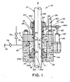
- the integrated apparatus 10 includes an elongated shaft 12 of an operational device subject to fluid leakage, such as a valve, pump or the like, where the use of a barrier fluid B in preventing leakage of a process fluid P and where the monitoring for leakage are desired.
- the shaft 12 which can be a rotatable or reciprocable component of the operational device, has a first portion 12A disposed in communication with the process fluid P which is at a first pressure and a second portion 12B axially displaced from the first portion 12A of the shaft 12 and disposed in communication with an external environment E, such as the ambient atmosphere.
- the integrated apparatus 10 in addition to the shaft 12 the integrated apparatus 10 basically includes a pressure intensifier 14 and a sealing arrangement 16.
- the pressure intensifier 14 of the apparatus 10 has an annular shape so as to surround and extend along the shaft 12.
- the annular-shaped pressure intensifier 14 defines an annular chamber 18 about the shaft 12 between the process fluid P and the external environment E.
- the chamber 18 contains the barrier fluid B therein.
- the pressure intensifier 14 also has an annular-shaped piston 20 which surrounds and is movable relative to the shaft 12.
- the piston 20 is disposed in the chamber 18 in communication with the process fluid P at an outer end 20A of the piston 20 and with the barrier fluid B at an inner end 20B of the piston 20 for enabling the maintenance of the barrier fluid B contained in the chamber 18 at a second pressure above the first pressure of the process fluid P.
- the sealing arrangement 16 of the apparatus 10 has an annular shape and is mounted to an inner peripheral surface 20C of the annular piston 20 within a central bore 22 defined by the inner peripheral surface 12C through the piston 10 and surrounds and engages the shaft 12 so as to define a seal, and preferably a dual seal, between an external cylindrical surface 12C of the shaft 12 and the inner peripheral surface 20C of the piston 20 which,prevents leakage of the process fluid P along the shaft 12 to the external environment E.
- the pressure intensifier 14 includes a housing or enclosure 24 stationarily supported relative to the shaft 12 which enclosure 24 can be part of a casing (not shown) of the operational device, for example part of a bonnet of a valve.
- the enclosure 24 has a pair of opposite spaced apart end walls 26, 28 and an annular sidewall 30 extending between and connected with the opposite end walls 26, 28 so as to define the chamber 18 containing the barrier fluid B within the enclosure 24.
- the enclosure 24 also has a pair of opposite openings 32, 34 each formed through a respective one of the opposite end walls 26, 28.
- the piston 20 is disposed within the chamber 18 adjacent the one end wall 26 of the enclosure 24 and the one opening 32 thereof and surrounds and is slidably movable along and relative to the shaft 12.
- the shaft 12 thus has a third portion 12D extending through and beyond the piston 20, the chamber 18 and the openings 32, 34 of the end walls 26, 28 of the enclosure 24 which interconnects the first and second portions 12A, 12B of the shaft 12.
- the chamber 18 has the annular shape and extends about the middle portion 12D of the shaft 12 and between the process fluid P at the first portion 12A of the shaft 12 and the external environment E at the second portion 12B of the shaft 12.
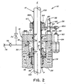
- the pressure intensifier 20 also includes an elongated spring 36 for imposing a bias force on the piston 20.
- the spring 36 surrounds the shaft 12 and can be disposed at any one of the different positions seen in FIGS. 1 to 4.
- the spring 36 is a compression type located outside of the chamber 18 adjacent to the other end wall 28 of the enclosure 24.
- the spring 36 is also a compression type located outside of the chamber 18 adjacent to the one end wall 26 of the enclosure 24 and the outer end 20A of the piston 20.
- the spring 36 is an extension type located inside of the chamber 18 between the inner end 20B of the piston 20 and the other end wall 28 of the enclosure 24.
- the spring 36 is also an extension type located outside of the chamber 18 and spaced from the other end wall 28 of the enclosure 24.
- the process fluid P at the first pressure presses through the one opening 32 in the one end wall 26 of the enclosure 24 and against an outer side 20A of the annular piston 20 in the direction toward the other end wall 28 of the enclosure 24.
- the spring 36 being mounted in any one of the illustrated positions relative to the enclosure 24 exerts a force on the piston in the same direction as the pressure of the process fluid P. Therefore, the pressure of the process fluid P and the force of the spring 36 together pressurize the barrier fluid B in the chamber 18, between the piston 20 and the other end wall 28 of the enclosure 24, to the second pressure slightly above the first pressure of the process fluid P, thus preventing leakage of process fluid P along the shaft 12 from the one end wall 26 to the other end wall 28 of the enclosure 24 to the external environment E.
- the establishment of the second pressure of the barrier fluid B, for instance about 5 to 10 percent, above the first pressure of the process fluid P is a result of the ratio of effective surface areas of the inner end 20B of the annular piston 20, the force of the spring 36 and the volume of an elongated hollow sleeve 38 connected to the inner end 20B of the annular piston 20 and movable with the annular piston 20 and protruding therefrom along the shaft 12 and from the chamber 18 at the other end wall 28 of the enclosure 24.
- the sealing arrangement 16 of the apparatus 10 more specifically, includes first and second annular-shaped sealing elements 40, 42, such as packing seals, seated within spaced-apart annular recesses 44 formed in the inner peripheral surface 20C of the annular piston 20.
- first and second sealing elements 40, 42 are axially spaced apart from one another along the third portion 12D of the shaft 12 and define the dual seals mentioned earlier.
- the annular piston 20 also has an elongated pressure port 46 defined therethrough and extending between the annular sealing elements 40, 42 for communicating barrier fluid pressure between the chamber 18 and the external surface 12C of the shaft 12.
- the two annular sealing elements 40, 42 are separated by the pressure port 46 and chamber 18 that surrounds the shaft 12 so that the first sealing element 40 seals the barrier fluid B from leaking into the process fluid P and the second sealing element 42 seals the barrier fluid B from leaking into the external environment E which, in turn, because of the greater pressure of the barrier fluid B over the process fluid P prevents leakage of the process fluid P into the barrier fluid B and into the external environment E.
- the pressure intensifier 14 also includes an annular-shaped external sealing element 48 seated in an annular recess 50 formed in outer peripheral surface 20D of the annular piston 20 which seals the piston 20 against an interior surface 30A of the annular sidewall 30 of the enclosure 24.
- the pressure intensifier 14 further includes an annular-shaped rod sealing element 52 seated in an annular recess 54 formed in the other end wall 28 of the enclosure 24 within the opening 34 through the end wall 28.
- the annular sealing element 52 seals about the piston sleeve 38 extending through the opening 34 of the enclosure 24 so as to prevent barrier fluid B from leaking about the sleeve 38 to the external environment E.
- the integrated apparatus 10 also includes a visual barrier fluid volume indicator mechanism, generally designated 56, being coupled to the piston 20 and responsive to movement of the piston 20 for visually indicating the position of the piston 20 and the volume of barrier fluid B contained in the chamber 18.
- the visual indicator mechanism 56 includes a stationary member 58 with a visual measurement scale 60 thereon having a plurality of symbols ranging from full to empty and from zero to ten and graduations associated with the symbols.
- the visual indicator mechanism 56 also includes an indicator member 62 movable with the piston 20 of the pressure intensifier 14 such that the indicator member 62 moves relative to the stationary member 58 so as to align with one of the graduations and symbols on the scale 60 that corresponds to the volume of barrier fluid B contained in the chamber 18 of the pressure intensifier 14.
- the indicator member 62 includes an anti-rotation collar 64 and a position indicator plate 66.
- the anti-rotation collar 64 is fixedly attached by a coupling key 67 to an outer end 38A of the sleeve 38.
- the position indicator plate 66 supported in a generally cantilevered fashion from one side of the anti-rotation collar 64 projects outwardly therefrom in a generally orthogonal relationship to the sleeve 38 and shaft 12. As shown in FIGS.
- the annular piston 20 and sleeve 38, the anti-rotation collar 64 and the position indicator plate 66 are prevented from rotating about the shaft 12 by means of the stationary member 58 which can take the form of an anti-rotation pin 68 screwed into the enclosure 24 and positioned upright across the path of the position indicator plate 66.
- the piston 20 with the sleeve 38, the anti-rotation collar 64 and the position indicator plate 66 are able to move axially along the shaft 12, depending upon the volume of barrier fluid B in the chamber 18, but cannot rotate about the shaft 12.
- the visual measurement scale 60 used for measuring the volume of barrier fluid B in the chamber 18 is marked on the anti-rotation pin 68.
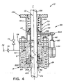
- FIG. 4 A somewhat different arrangement that prevents rotation is shown in FIG. 4.
- An extension 70 on the enclosure 24 has an elongated slot or window 72 defined in a side of the extension 70.
- the position indicator plate 66 extends through the window 72 of the extension 70 so as to thereby prevent rotation of the piston 20 with the sleeve 38, the anti-rotation collar 64 and the position indicator plate 66.
- the visual measurement scale 60 is now marked on the outside of the extension 70, which now functions as the stationary member 58, alongside the window 72 for measuring the volume of the barrier fluid B in the chamber 18.
- the spring 36 is either a compression or extension type and is located inside or outside of the enclosure 24. In FIGS. 1 and 4, the spring 36 is located between the anti-rotation collar 64 and either the other end wall 28 of the enclosure 24 in FIG. 1 or the outer end 70A of the enclosure extension 70 in FIG. 4.
- the spring bias force overcomes seal friction and develops a small residual pressure in the chamber 18 when the process fluid pressure is zero, helping the first and second sealing elements 40, 42 to seat and seal better at lower pressure.
- the bias force of the spring 36 also prevents the pressure of the barrier fluid B in the chamber 18 from dropping below the pressure of the process fluid P which may occur when the shaft 12 is moving toward the process fluid P.
- the friction from the sealing elements 40, 42 carries or pulls along the piston 20 with the shaft 12, which would cause the pressure of the barrier fluid B to drop below the pressure of the process fluid P if the spring bias force was not utilized.
- the chamber 18 is first evacuated using a vacuum pump connected to a purge valve 74. After the chamber 18 has been evacuated, the purge valve 74 is turned off. A barrier fluid supply pump (not shown) is connected to a fill coupling 76 and then is operated to fill the chamber 18. Another method of filling the chamber 18, not requiring a vacuum pump, can be used when the barrier fluid is a liquid.
- the chamber 18 is first filled using the fill coupling 76 connected to the barrier fluid supply pump. Then, the purge valve 74 is opened to bleed off gas trapped in the chamber 18. This process is repeated until all gas is purged from the chamber 18.
- a fill check valve 78 maintains the barrier fluid pressure after the chamber 18 has been filled.
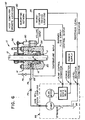
- a linear transducer 80 is mounted to a side of the annular sidewall 30 of the enclosure 24 and has a linearly reciprocal rod 82 being connected to an outer end 66A of the position indicator plate 66.
- the rod 82 moves relative to (extends or retracts from) a cylinder 84 of the transducer 80 in response to axial movement of the piston 20, sleeve 38, anti-rotation collar 64 and position indicator plate 66.
- the linear transducer 80 generates electrical signals or data that electronically locates the position of the annular piston 20 within the chamber 18 and thereby determines the volume of the barrier fluid therein.
- the electrical data are relayed as inputs to a microcomputer 86 at the location of the operational device.
- Input data from a temperature transducer 88 disposed in the chamber 18 also is relayed to the microcomputer 86.
- the data from these two transducers 80, 88 are stored in the memory of the microcomputer 86 along with the date and time when the data was taken. If the microcomputer 86 is equipped with a display, an average leakage rate can be calculated and displayed at that location.
- a reporting network 90 connects with the microcomputer 86 to a host computer 92, allowing the transfer of data to and from the microcomputer 86.
- the transducer data, date and time data, and leakage calculations from the microcomputer 86 are transferred to the host computer 92.
- the data sent to the host computer 92 for a particular operational device is stored in a maintenance database and is used by the software of the host computer 92 to perform maintenance analyses, including forecasting economic seal replacement dates and generating maintenance reports that determine maintenance priorities.
- a removable barrier fluid supply 94 connectable to the enclosure 24.
- the sealing elements 40, 42 in the chamber 18 begin to leak, the barrier fluid leakage may be slow or intermittent and the particular operational device may not need immediate attention. However, if the device begins to leak barrier fluid at a high rate, the leakage must be controlled or there is a danger of process fluid leakage.
- the removable barrier fluid supply 94 can be connected to the enclosure 24 on a temporary basis until the device can be resealed during scheduled maintenance.
- the microcomputer 86 turns on the removable barrier fluid supply 94 and fills the chamber 18 when the volume of barrier fluid therein becomes too low.
- the microcomputer 86 also monitors the fluid level of the barrier fluid reservoir 96.
- the microcomputer 86 If the fluid level of the reservoir 96 is low, the microcomputer 86 notifies the host computer 92 so that the reservoir 96 can be filled manually. Since the barrier fluid has been selected so as not to harm the environment, there is no concern about release or spillage of barrier fluid. When scheduled maintenance allows, the removable barrier fluid supply 94 is removed and the device is resealed.
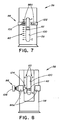
- FIGS. 7 and 8 there is illustrated additional embodiments of the visual barrier fluid volume indicator mechanism 56 which can be used with the pressure intensifier 14 of the integrated apparatus 10 described above and also with the control apparatus disclosed in the aforementioned U.S. patents granted to the inventor herein.
- these embodiments of the visual indicator mechanism 56 further include a manually adjustable position indicator 98 in the form of a C-shaped band which extends snugly about the stationary member 58 and has a pair of opposite ends 98A spaced apart from one another at the location of a window 100 in the stationary member 58.
- the manual position indicator 98 has a slot 102 in each of its opposite ends 98A through which an operator can observe the respective symbol (number) on the visual measurement scale 60 with which the manual position indicator 98 is aligned.
- the manual position indicator 98 snugly fits about the stationary member 58 so that it will remain at any position to which it has been slidably moved and placed along the stationary member 58.
- the manual position indicator 98 has a pointer 104 attached to and extending from one of its opposite ends 98A.
- the pointer 104 can be aligned with a given symbol on the scale 58 upon slidably moving the indicator 98 along the stationary member 58 to the desired position.
- the manual position indicator 98 in FIG. 8 also has a set screw 106 which can be tightened to retain the indicator 98 at the desired position and loosened for moving the indicator 98.
- the purpose of the manual position indicator 98 in both embodiments is to mark the position of the barrier fluid volume manually so that a later position of the movable indicator member 62 of the visual indicator mechanism 56 can be compared to its earlier position now marked by the manual position indicator 98. In such manner, a change of barrier fluid volume over time can be visually noted and "manually" measured.
- the integrated assembly 10 primarily functions to prevent process fluid P from leaking into the external environment E by using a higher pressure barrier fluid B and to extend the service life of the barrier fluid sealing arrangement 16 by monitoring the sealing arrangement for leakage.
- Secondary functions which can be associated with the integrated assembly 10 include calculating barrier fluid leakage volume, reporting leakage time and date information over the reporting network 90, forecasting economic seal replacement dates, and generating maintenance reports that determine maintenance priorities on the host computer 92.
Landscapes
- Engineering & Computer Science (AREA)
- General Engineering & Computer Science (AREA)
- Mechanical Engineering (AREA)
- Measuring Fluid Pressure (AREA)
- Sealing Devices (AREA)
- Materials For Medical Uses (AREA)
- Compressor (AREA)
- Pressure Vessels And Lids Thereof (AREA)
- Sealing Using Fluids, Sealing Without Contact, And Removal Of Oil (AREA)
Claims (16)
- Eine Sperrfluid-Dichtungseinrichtung (10), die eine längliche Welle (12) einer wirksamen Vorrichtung, einen Druckverstärker (14) und eine Dichtungsanordnung (16) umschließt, wobei besagte Einrichtung (10) dadurch gekennzeichnet ist, dass :besagte längliche Welle (12) einen ersten Teil (12A) in Kommunikation mit einem Prozessfluid (P) auf einem ersten Druck und einen zweiten Teil (12B) axial von besagtem ersten Teil (12A) versetzt und in Kommunikation mit einer Außenumgebung (E) aufweist ;wobei besagter Druckverstärker (14) eine ringförmige Form hat, um besagte Welle (12) zu umgeben und sich entlang dieser zu erstrecken, und besagter Druckverstärker eine Kammer (18) definiert, die sich um besagte Welle (12) zwischen dem Prozessfluid (P) und der Außenumgebung (E) erstreckt und darin Sperrfluid (B) enthält, wobei besagter Druckverstärker (14) weiter einen ringförmigen Kolben (20) aufweist, der besagte Welle (12) umgibt und relativ zu dieser bewegbar ist und in besagter Kammer (18) in Kommunikation mit dem Prozessfluid (P) und Sperrfluid (B) ist, um das Halten des Sperrfluids (B) in besagter Kammer (18) auf einem zweiten Druck über dem ersten Druck des Prozessfluids (P) zu ermöglichen ; undbesagte Dichtungsanordnung (16) eine ringförmige Form hat und an besagtem ringförmigen Kolben (20) montiert ist und besagte Welle (12) umschließt, um eine Abdichtung zwischen besagter Welle und besagtem Kolben zu definieren, sodass besagter Druckverstärker (14) und besagte Dichtungsanordnung (16) zusammenwirken, um Lecken von Prozessfluid (P) entlang besagter Welle (12) zur Außenumgebung (E) zu verhindern.
- Die Einrichtung von Anspruch 1, dadurch gekennzeichnet, dass besagter Kolben (20) in Kommunikation mit dem Prozessfluid (P) an einem äußeren Ende (20A) besagten Kolbens (20) und in Kommunikation mit dem Sperrfluid (B) an einem inneren Ende (20B) besagten Kolbens (20) angeordnet ist.
- Die Einrichtung von Anspruch 1, dadurch gekennzeichnet, dass besagte Dichtungsanordnung (16) ein Paar ringförmiger Dichtungselemente (40, 42) beinhaltet, die entlang besagter Welle (12) axial voneinander beabstandet sind.
- Die Einrichtung von Anspruch 3, dadurch gekennzeichnet, dass besagter Kolben (20) eine zwischen besagten ringförmigen Dichtungselementen (40, 42) definierte Druckdurchlassöffnung (46) zum Kommunizieren von Sperrfluiddruck zwischen besagter Kammer (18) und besagter Welle (12) aufweist.
- Die Einrichtung von Anspruch 1, dadurch gekennzeichnet, dass besagter Druckverstärker (14) ein Gehäuse (24) mit einem Paar einander gegenüberliegender beabstandeter Endwände (26, 28) und einer ringförmigen Seitenwand (30) aufweist, die sich zwischen den einander gegenüberliegenden Endwänden (26, 28) erstreckt und mit diesen verbunden ist, um dazwischen besagte Kammer (18) innerhalb besagten Gehäuses (24) zu definieren.
- Die Einrichtung von Anspruch 5, dadurch gekennzeichnet, dass besagtes Gehäuse (24) ein Paar einander gegenüberliegender Öffnungen (32, 34) aufweist, die jede durch eine jeweilige der einander gegenüberliegenden Endwände (26, 28) gebildet sind, sodass besagte Welle (12) sich durch besagtes Gehäuse (24) und durch besagte Öffnungen (32, 34) besagter Endwände (26, 28) davon hindurch und durch besagte Kammer (18) besagten Gehäuses (24) erstreckt.
- Die Einrichtung von Anspruch 1, dadurch gekennzeichnet, dass besagter Druckverstärker (14) weiter eine längliche Feder (36) umfasst, die besagten ringförmigen Kolben (20) vorspannt, um besagten Kolben (20) bei der Aufrechterhaltung des zweiten Drucks des Sperrfluids (B) über dem ersten Druck des Prozessfluids (P) zu unterstützen.
- Die Einrichtung von Anspruch 1, dadurch gekennzeichnet, dass besagter Druckverstärker (14) weiter eine längliche Buchse (38) umfasst, die an einem Ende mit besagtem ringförmigen Kolben (20) verbunden und damit bewegbar ist und von dort entlang besagter Welle (12) und durch und von besagter Kammer (18) zu einem Teil zum Anschluss an einen Sperrfluid-Volumenanzeigemechanismus (56) ragt, um den Anzeigemechanismus (56) auf die Bewegung besagten Kolbens (20) ansprechend zu machen.
- Die Einrichtung von Anspruch 1, dadurch gekennzeichnet, dass besagter Druckverstärker (14) weiter eine längliche Buchse (38) umfasst, die an einem Ende mit besagtem ringförmigen Kolben (20) verbunden und damit bewegbar ist und von dort entlang besagter Welle (12) und durch und von besagter Kammer (18) zu einem Teil zum Anschluss an einen linearen Transducer zum Messen der Bewegung besagten Kolbens ragt.
- Die Einrichtung von Anspruch 1, weiter umfassend :eine Sperrfluidzufuhr, die an besagtes Gehäuse anschließbar ist, um selektiv besagte Kammer mit Sperrfluid (B) zu füllen.
- Die Einrichtung von Anspruch 1, weiter umfassend :einen linearen Transducer (80), gekoppelt an besagten ringförmigen Kolben (20) zum Generieren elektrischer Daten, der elektronisch die Position besagten ringförmigen Kolbens (20) innerhalb besagter Kammer (18) lokalisiert und dadurch das Volumen von Sperrfluid (B) in besagter Kammer (18) ermittelt.
- Die Einrichtung von Anspruch 11, weiter umfassend :einen Temperaturtransducer (88), der sich in besagter Kammer befindet und elektrische Daten generiert, die die Temperatur des Sperrfluids (B) in besagter Kammer (18) darstellen ; undeinen Mikrocomputer (86), der die von besagtem linearen Transducer (80) und Temperaturtransducer (88) generierten Daten empfängt und speichert.
- Die Einrichtung von Anspruch 1, weiter umfassend :einen visuellen Sperrfluid-Volumenanzeigemechanismus (56), der an besagten Kolben (20) gekoppelt ist und auf Bewegung des Kolbens (20) reagiert, um visuell das Volumen von Sperrfluid (B) in besagter Kammer (18) anzuzeigen.
- Die Einrichtung von Anspruch 13, dadurch gekennzeichnet, dass besagter visueller Anzeigemechanismus (56) folgendes umfasst :ein stationäres Element (58) mit einer Messskala (60) mit darauf einer Vielzahl von Symbolen, die sich von etwa voll bis auf etwa leer belaufen ; undein Anzeigeelement (62), das mit besagtem Kolben (20) besagten Druckverstärkers (14) entlang besagter Welle (12) bewegbar ist, um sich zu einem der besagten Symbole auf besagter Skala auszurichten, das dem in besagter Kammer (18) besagten Druckverstärkers (14) enthaltenen Volumen von Sperrfluid (B) entspricht.
- Die Einrichtung von Anspruch 14, dadurch gekennzeichnet, dass besagter visueller Anzeigemechanismus (56) weiter einen manuell einstellbaren Positionsanzeiger (98) umfasst, der sich zumindest teilweise über besagtes stationäres Element (58) erstreckt und verschieblich entlang diesem bewegbar ist, um besagten Positionsanzeiger (98) manuell zu einem gegebenen Symbol auf besagter Skala auszurichten, um manuell eine Sperrfluid-Volumenmessung festzuhalten, um sie mit einer späteren Messung durch besagtes Anzeigeelement zu vergleichen.
- Die Einrichtung von Anspruch 15, dadurch gekennzeichnet, dass besagter visueller Anzeigemechanismus (56) weiter ein einstellbares Befestigungselement (106) an besagtem manuell einstellbaren Positionsanzeiger (98) umfasst, um besagten Positionsindikator (98) an einer gewünschten Position entlang besagtem stationären Element (58) lösbar zu befestigen.
Applications Claiming Priority (5)
| Application Number | Priority Date | Filing Date | Title |
|---|---|---|---|
| US9687798P | 1998-08-17 | 1998-08-17 | |
| US9673898P | 1998-08-17 | 1998-08-17 | |
| US96877P | 1998-08-17 | ||
| US96738P | 1998-08-17 | ||
| PCT/US1999/018647 WO2000009956A2 (en) | 1998-08-17 | 1999-08-16 | Integrated barrier fluid sealing apparatus with visual volume indicator |
Publications (3)
| Publication Number | Publication Date |
|---|---|
| EP1104518A2 EP1104518A2 (de) | 2001-06-06 |
| EP1104518A4 EP1104518A4 (de) | 2004-12-01 |
| EP1104518B1 true EP1104518B1 (de) | 2006-04-19 |
Family
ID=26792025
Family Applications (1)
| Application Number | Title | Priority Date | Filing Date |
|---|---|---|---|
| EP99942238A Expired - Lifetime EP1104518B1 (de) | 1998-08-17 | 1999-08-16 | Integrierte abdichtungsschutzvorrichtung gegen flüssigkeiten mit visuellervolumenangabe |
Country Status (7)
| Country | Link |
|---|---|
| US (1) | US6161835A (de) |
| EP (1) | EP1104518B1 (de) |
| AT (1) | ATE323857T1 (de) |
| AU (1) | AU5566299A (de) |
| CA (1) | CA2340631C (de) |
| DE (1) | DE69930943D1 (de) |
| WO (1) | WO2000009956A2 (de) |
Families Citing this family (16)
| Publication number | Priority date | Publication date | Assignee | Title |
|---|---|---|---|---|
| US6953084B2 (en) | 2003-01-10 | 2005-10-11 | Woodward Governor Company | Actuator for well-head valve or other similar applications and system incorporating same |
| US7118114B2 (en) * | 2003-05-15 | 2006-10-10 | Woodward Governor Company | Dynamic sealing arrangement for movable shaft |
| US20070120084A1 (en) * | 2005-11-29 | 2007-05-31 | Stumbo Steven C | Fully independent, redundant fluid energized sealing solution with secondary containment |
| US7426936B2 (en) * | 2005-11-29 | 2008-09-23 | Woodward Governor Company | Fully independent, redundant fluid energized sealing solution with secondary containment |
| NO325803B1 (no) * | 2006-10-13 | 2008-07-21 | Framo Eng As | Anordning ved tetningssystem |
| US20090151956A1 (en) * | 2007-12-12 | 2009-06-18 | John Johansen | Grease injection system for riserless light well intervention |
| GB201016759D0 (en) * | 2010-10-06 | 2010-11-17 | Nat Oilwell Varco Lp | Seal leakage detection |
| NO333696B1 (no) * | 2010-12-17 | 2013-08-26 | Vetco Gray Scandinavia As | System og fremgangsmate for momentan hydrostatisk drift av hydrodynamiske aksiallagre i en vertikal fluidfortregningsmodul |
| US9304054B2 (en) | 2013-03-15 | 2016-04-05 | Halliburton Energy Services, Inc. | Non-electronic air chamber pressure sensor |
| ITMI20142265A1 (it) * | 2014-12-29 | 2016-06-29 | Nuovo Pignone Srl | Dispositivo di tenuta per lo stelo di una valvola |
| CN108474243A (zh) | 2015-11-18 | 2018-08-31 | 伍德沃德有限公司 | 无线控制阀 |
| IT201600085635A1 (it) * | 2016-08-17 | 2018-02-17 | Nuovo Pignone Tecnologie Srl | Tenuta per l'asta di un pistone |
| CN107100999B (zh) * | 2017-05-27 | 2018-07-03 | 李荣耀 | 镜油离心密封装置 |
| KR102181092B1 (ko) * | 2020-03-20 | 2020-11-20 | 고기창 | 밸브의 누설 차단장치 |
| US12473978B2 (en) * | 2021-05-13 | 2025-11-18 | The Texas A&M University System | Fluid sealing of moving shafts for high-pressure chambers |
| US12234926B1 (en) | 2023-08-10 | 2025-02-25 | Fisher Controls International Llc | Packing system of a valve assembly |
Family Cites Families (41)
| Publication number | Priority date | Publication date | Assignee | Title |
|---|---|---|---|---|
| US1447824A (en) * | 1921-06-03 | 1923-03-06 | Alexander M Thompson | Oil indicator for vehicles |
| US1636752A (en) * | 1927-04-01 | 1927-07-26 | William E Mitchell | Indicating device for visible-gasoline tanks |
| US1721737A (en) * | 1927-07-29 | 1929-07-23 | Bryan P Joyce | Pressure-fluid packing |
| US3176996A (en) * | 1962-10-12 | 1965-04-06 | Barnett Leon Truman | Oil balanced shaft seal |
| US3259390A (en) * | 1963-06-17 | 1966-07-05 | Dorothy L Sanford | Hydraulic balanced self-aligning shaft seal |
| US3297329A (en) * | 1964-08-26 | 1967-01-10 | Ingersoll Rand Co | Pump seal injection control |
| US3266722A (en) * | 1965-04-06 | 1966-08-16 | Charles E W Hobbis | Guard band indicator |
| DE1600584B1 (de) * | 1967-04-26 | 1970-07-02 | Sicherungsgeraetebau Gmbh | Fluessigkeitsverschluss |
| US3589737A (en) * | 1969-02-17 | 1971-06-29 | Crane Packing Co | Mechanical seal for a vertical rotating |
| US3749411A (en) * | 1971-07-19 | 1973-07-31 | Nettco Corp | Shaft sealing system |
| IT959643B (it) * | 1972-04-24 | 1973-11-10 | Nuovo Pignone Spa | Dispositivo accumulatore di olio ad elevata pressione e regolatore della stessa da impiegarsi per tenute ad olio di compressori cen trifughi ad elevata pressione |
| CH572174A5 (de) * | 1972-06-09 | 1976-01-30 | Burgmann Dichtungswerk Feodor | |
| US3831381A (en) * | 1973-05-02 | 1974-08-27 | J Swearingen | Lubricating and sealing system for a rotary power plant |
| US3987663A (en) * | 1974-10-29 | 1976-10-26 | Federal-Mogul Corporation | Method and apparatus for quickly testing the sealing effectiveness of a radial-lip shaft seal |
| FR2317528A1 (fr) * | 1975-07-11 | 1977-02-04 | Creusot Loire | Dispositif d'etancheite contre les sorties de gaz aux extremites de l'arbre rotatif d'un compresseur centrifuge |
| US4014555A (en) * | 1976-02-03 | 1977-03-29 | Jean Louis Jacottet | Hydrostatic sealing device |
| US4114058A (en) * | 1976-09-03 | 1978-09-12 | Westinghouse Electric Corp. | Seal arrangement for a discharge chamber for water cooled turbine generator rotor |
| JPS5442548A (en) * | 1977-09-10 | 1979-04-04 | Kenji Asano | Leak seal liquid return apparatus for stirling engine |
| DE3030405A1 (de) * | 1980-08-12 | 1982-04-01 | Haagen & Rinau, 2800 Bremen | Anordnung zum abdichten einer durch wechseldruck beaufschlagten welle |
| US4412447A (en) * | 1981-07-23 | 1983-11-01 | Mcmahan Walter C | Disposable irrigation gauge |
| US4505115A (en) * | 1981-09-08 | 1985-03-19 | Arbuckle Donald P | Fluidic transformer apparatus with feedback |
| FR2532424A1 (fr) * | 1982-08-27 | 1984-03-02 | Cit Alcatel | Dispositif de mesure et d'affichage du taux q de fuite pour un detecteur de fuites a gaz traceur |
| US4408766A (en) * | 1982-11-29 | 1983-10-11 | Longyear Australia Pty. Ltd. | Rotary seal apparatus with dual self-centering annular face seals |
| DE3426705C2 (de) * | 1984-07-20 | 1986-09-04 | Oskar Krieger Maschinen- und Metallbau AG, Muttenz | Dichtungsanordnung zur Absperrung eines Schaft- bzw. Wellendurchtrittes |
| GB8520526D0 (en) * | 1985-08-15 | 1985-09-18 | Brown Bros & Co Ltd | Sealing apparatus for fluids |
| US4922719A (en) * | 1987-10-26 | 1990-05-08 | Arbuckle Donald P | Fluidic transformer with sealed cylinder and check valves in pistons |
| US5031509A (en) * | 1988-03-25 | 1991-07-16 | Titan Tool, Inc. | Anti-leak seal for pump motor |
| CA1314864C (en) * | 1989-04-14 | 1993-03-23 | Computalog Gearhart Ltd. | Compressive seal and pressure control arrangements for downhole tools |
| US5249812A (en) * | 1990-03-12 | 1993-10-05 | John Crane Inc. | Barrier seal systems |
| DE69106032T2 (de) * | 1990-04-23 | 1995-08-03 | Tanken Seiko Kk | Verfahren zur Vorhersage von Abweichungen in mechanischen Dichtungen und Gerät zu ihrer Vorhersage. |
| US5209495A (en) * | 1990-09-04 | 1993-05-11 | Palmour Harold H | Reciprocating rod pump seal assembly |
| US5267736A (en) * | 1990-09-05 | 1993-12-07 | Blohm & Voss Ag | Sealing apparatus for rotating shafts, in particular stern tube seal for the propeller shaft of a ship |
| US5147015A (en) * | 1991-01-28 | 1992-09-15 | Westinghouse Electric Corp. | Seal oil temperature control method and apparatus |
| US5244183A (en) * | 1991-03-20 | 1993-09-14 | Keystone International Holdings Corp. | Fugitive emission sealing assembly |
| US5226509A (en) * | 1992-02-03 | 1993-07-13 | At-A-Glance, Inc. | At-a-glance brake travel indicator |
| US5474303A (en) * | 1993-04-15 | 1995-12-12 | Coles; Carl R. | Actuator rod hermetic sealing apparatus employing concentric bellows and pressure compensating sealing liquid with liquid monitoring system |
| DE9307024U1 (de) * | 1993-05-08 | 1993-07-22 | Hennecke GmbH, 51373 Leverkusen | Wellendurchführung mit Sperrflüssigkeitsabdichtung |
| US5502435A (en) * | 1994-04-06 | 1996-03-26 | Ralston; Douglas E. | Method and system for monitoring circuit breaker gas pressure |
| US5535136A (en) * | 1994-05-17 | 1996-07-09 | Standifer; Larry R. | Detection and quantification of fluid leaks |
| US5746435A (en) * | 1994-09-30 | 1998-05-05 | Arbuckle; Donald P. | Dual seal barrier fluid leakage control method |
| US5636847A (en) * | 1995-09-13 | 1997-06-10 | Chesterton International Company | Dual face seal clean barrier fluid and dynamic pressure control system |
-
1999
- 1999-08-16 US US09/375,313 patent/US6161835A/en not_active Expired - Fee Related
- 1999-08-16 CA CA002340631A patent/CA2340631C/en not_active Expired - Fee Related
- 1999-08-16 AU AU55662/99A patent/AU5566299A/en not_active Abandoned
- 1999-08-16 AT AT99942238T patent/ATE323857T1/de not_active IP Right Cessation
- 1999-08-16 EP EP99942238A patent/EP1104518B1/de not_active Expired - Lifetime
- 1999-08-16 DE DE69930943T patent/DE69930943D1/de not_active Expired - Lifetime
- 1999-08-16 WO PCT/US1999/018647 patent/WO2000009956A2/en not_active Ceased
Also Published As
| Publication number | Publication date |
|---|---|
| CA2340631A1 (en) | 2000-02-24 |
| AU5566299A (en) | 2000-03-06 |
| EP1104518A2 (de) | 2001-06-06 |
| DE69930943D1 (de) | 2006-05-24 |
| ATE323857T1 (de) | 2006-05-15 |
| CA2340631C (en) | 2005-06-07 |
| EP1104518A4 (de) | 2004-12-01 |
| US6161835A (en) | 2000-12-19 |
| WO2000009956A2 (en) | 2000-02-24 |
| WO2000009956A3 (en) | 2000-06-15 |
Similar Documents
| Publication | Publication Date | Title |
|---|---|---|
| EP1104518B1 (de) | Integrierte abdichtungsschutzvorrichtung gegen flüssigkeiten mit visuellervolumenangabe | |
| US5474303A (en) | Actuator rod hermetic sealing apparatus employing concentric bellows and pressure compensating sealing liquid with liquid monitoring system | |
| US5372352A (en) | Apparatus for sealing a fluid carrying device | |
| EP2753908B1 (de) | System zur erkennung flüchtiger emissionen in einer ventilverpackung | |
| US5170659A (en) | Apparatus and method for detecting fluid leakage | |
| US5203370A (en) | Mounting apparatus with fugitive emission collection means for directly coupling a rotary valve to an actuator having rotary drive means | |
| US5244183A (en) | Fugitive emission sealing assembly | |
| EP3430367B1 (de) | Detektion flüchtiger emissionen | |
| US4635901A (en) | Position indicator for valves | |
| CN100389280C (zh) | 特别适用于气体容器的具有流体状态指示装置的流量控制阀 | |
| WO2012045995A2 (en) | Seal leakage detection | |
| GB2273167A (en) | Fluid supply system with leak detection device. | |
| GB2025577A (en) | Valve arrangements | |
| JP2002513901A (ja) | 制御弁内のピストン用封入インジケータ | |
| EP1522774B1 (de) | Durchflussregelventil | |
| US6899129B2 (en) | Shutoff valve and related methods | |
| GB2102351A (en) | Pressure indicating device | |
| US3335610A (en) | Safety device for pressure gauges | |
| US3496776A (en) | Pressure gauge | |
| JP5429965B2 (ja) | 圧力調整器 | |
| WO1996010707A1 (en) | Dual seal barrier fluid leakage control apparatus | |
| JP3388311B2 (ja) | 液圧装置の保守点検システム | |
| US6694819B1 (en) | Pressure gauge with automatically operated pressure relief valve | |
| EP0026575A1 (de) | Druckentlastungsvorrichtung mit Ventil und Druckanzeiger | |
| US6889547B1 (en) | Liquid level input assembly for measuring the height of a column of liquid |
Legal Events
| Date | Code | Title | Description |
|---|---|---|---|
| PUAI | Public reference made under article 153(3) epc to a published international application that has entered the european phase |
Free format text: ORIGINAL CODE: 0009012 |
|
| 17P | Request for examination filed |
Effective date: 20010313 |
|
| AK | Designated contracting states |
Kind code of ref document: A2 Designated state(s): AT BE CH CY DE DK ES FI FR GB GR IE IT LI LU MC NL PT SE |
|
| AX | Request for extension of the european patent |
Free format text: AL;LT;LV;MK;RO;SI |
|
| A4 | Supplementary search report drawn up and despatched |
Effective date: 20041018 |
|
| RIC1 | Information provided on ipc code assigned before grant |
Ipc: 7F 16K 41/00 B Ipc: 7F 16K 37/00 B Ipc: 7F 16J 15/40 B Ipc: 7F 16J 15/32 B Ipc: 7F 16J 15/16 A |
|
| 17Q | First examination report despatched |
Effective date: 20050119 |
|
| GRAP | Despatch of communication of intention to grant a patent |
Free format text: ORIGINAL CODE: EPIDOSNIGR1 |
|
| GRAS | Grant fee paid |
Free format text: ORIGINAL CODE: EPIDOSNIGR3 |
|
| GRAA | (expected) grant |
Free format text: ORIGINAL CODE: 0009210 |
|
| AK | Designated contracting states |
Kind code of ref document: B1 Designated state(s): AT BE CH CY DE DK ES FI FR GB GR IE IT LI LU MC NL PT SE |
|
| PG25 | Lapsed in a contracting state [announced via postgrant information from national office to epo] |
Ref country code: NL Free format text: LAPSE BECAUSE OF FAILURE TO SUBMIT A TRANSLATION OF THE DESCRIPTION OR TO PAY THE FEE WITHIN THE PRESCRIBED TIME-LIMIT Effective date: 20060419 Ref country code: LI Free format text: LAPSE BECAUSE OF FAILURE TO SUBMIT A TRANSLATION OF THE DESCRIPTION OR TO PAY THE FEE WITHIN THE PRESCRIBED TIME-LIMIT Effective date: 20060419 Ref country code: IT Free format text: LAPSE BECAUSE OF FAILURE TO SUBMIT A TRANSLATION OF THE DESCRIPTION OR TO PAY THE FEE WITHIN THE PRESCRIBED TIME-LIMIT;WARNING: LAPSES OF ITALIAN PATENTS WITH EFFECTIVE DATE BEFORE 2007 MAY HAVE OCCURRED AT ANY TIME BEFORE 2007. THE CORRECT EFFECTIVE DATE MAY BE DIFFERENT FROM THE ONE RECORDED. Effective date: 20060419 Ref country code: FI Free format text: LAPSE BECAUSE OF FAILURE TO SUBMIT A TRANSLATION OF THE DESCRIPTION OR TO PAY THE FEE WITHIN THE PRESCRIBED TIME-LIMIT Effective date: 20060419 Ref country code: CH Free format text: LAPSE BECAUSE OF FAILURE TO SUBMIT A TRANSLATION OF THE DESCRIPTION OR TO PAY THE FEE WITHIN THE PRESCRIBED TIME-LIMIT Effective date: 20060419 Ref country code: BE Free format text: LAPSE BECAUSE OF FAILURE TO SUBMIT A TRANSLATION OF THE DESCRIPTION OR TO PAY THE FEE WITHIN THE PRESCRIBED TIME-LIMIT Effective date: 20060419 Ref country code: AT Free format text: LAPSE BECAUSE OF FAILURE TO SUBMIT A TRANSLATION OF THE DESCRIPTION OR TO PAY THE FEE WITHIN THE PRESCRIBED TIME-LIMIT Effective date: 20060419 |
|
| REG | Reference to a national code |
Ref country code: GB Ref legal event code: FG4D |
|
| REF | Corresponds to: |
Ref document number: 69930943 Country of ref document: DE Date of ref document: 20060524 Kind code of ref document: P |
|
| REG | Reference to a national code |
Ref country code: IE Ref legal event code: FG4D |
|
| PG25 | Lapsed in a contracting state [announced via postgrant information from national office to epo] |
Ref country code: SE Free format text: LAPSE BECAUSE OF FAILURE TO SUBMIT A TRANSLATION OF THE DESCRIPTION OR TO PAY THE FEE WITHIN THE PRESCRIBED TIME-LIMIT Effective date: 20060719 Ref country code: DK Free format text: LAPSE BECAUSE OF FAILURE TO SUBMIT A TRANSLATION OF THE DESCRIPTION OR TO PAY THE FEE WITHIN THE PRESCRIBED TIME-LIMIT Effective date: 20060719 |
|
| PG25 | Lapsed in a contracting state [announced via postgrant information from national office to epo] |
Ref country code: DE Free format text: LAPSE BECAUSE OF FAILURE TO SUBMIT A TRANSLATION OF THE DESCRIPTION OR TO PAY THE FEE WITHIN THE PRESCRIBED TIME-LIMIT Effective date: 20060720 |
|
| PG25 | Lapsed in a contracting state [announced via postgrant information from national office to epo] |
Ref country code: ES Free format text: LAPSE BECAUSE OF FAILURE TO SUBMIT A TRANSLATION OF THE DESCRIPTION OR TO PAY THE FEE WITHIN THE PRESCRIBED TIME-LIMIT Effective date: 20060730 |
|
| PG25 | Lapsed in a contracting state [announced via postgrant information from national office to epo] |
Ref country code: IE Free format text: LAPSE BECAUSE OF NON-PAYMENT OF DUE FEES Effective date: 20060816 |
|
| PG25 | Lapsed in a contracting state [announced via postgrant information from national office to epo] |
Ref country code: MC Free format text: LAPSE BECAUSE OF NON-PAYMENT OF DUE FEES Effective date: 20060831 |
|
| PG25 | Lapsed in a contracting state [announced via postgrant information from national office to epo] |
Ref country code: PT Free format text: LAPSE BECAUSE OF FAILURE TO SUBMIT A TRANSLATION OF THE DESCRIPTION OR TO PAY THE FEE WITHIN THE PRESCRIBED TIME-LIMIT Effective date: 20060919 |
|
| NLV1 | Nl: lapsed or annulled due to failure to fulfill the requirements of art. 29p and 29m of the patents act | ||
| REG | Reference to a national code |
Ref country code: CH Ref legal event code: PL |
|
| PLBE | No opposition filed within time limit |
Free format text: ORIGINAL CODE: 0009261 |
|
| STAA | Information on the status of an ep patent application or granted ep patent |
Free format text: STATUS: NO OPPOSITION FILED WITHIN TIME LIMIT |
|
| GBPC | Gb: european patent ceased through non-payment of renewal fee |
Effective date: 20060816 |
|
| 26N | No opposition filed |
Effective date: 20070122 |
|
| EN | Fr: translation not filed | ||
| PG25 | Lapsed in a contracting state [announced via postgrant information from national office to epo] |
Ref country code: GB Free format text: LAPSE BECAUSE OF NON-PAYMENT OF DUE FEES Effective date: 20060816 |
|
| PG25 | Lapsed in a contracting state [announced via postgrant information from national office to epo] |
Ref country code: GR Free format text: LAPSE BECAUSE OF FAILURE TO SUBMIT A TRANSLATION OF THE DESCRIPTION OR TO PAY THE FEE WITHIN THE PRESCRIBED TIME-LIMIT Effective date: 20060720 Ref country code: FR Free format text: LAPSE BECAUSE OF FAILURE TO SUBMIT A TRANSLATION OF THE DESCRIPTION OR TO PAY THE FEE WITHIN THE PRESCRIBED TIME-LIMIT Effective date: 20070309 |
|
| PG25 | Lapsed in a contracting state [announced via postgrant information from national office to epo] |
Ref country code: LU Free format text: LAPSE BECAUSE OF NON-PAYMENT OF DUE FEES Effective date: 20060816 |
|
| PG25 | Lapsed in a contracting state [announced via postgrant information from national office to epo] |
Ref country code: FR Free format text: LAPSE BECAUSE OF FAILURE TO SUBMIT A TRANSLATION OF THE DESCRIPTION OR TO PAY THE FEE WITHIN THE PRESCRIBED TIME-LIMIT Effective date: 20060419 Ref country code: CY Free format text: LAPSE BECAUSE OF FAILURE TO SUBMIT A TRANSLATION OF THE DESCRIPTION OR TO PAY THE FEE WITHIN THE PRESCRIBED TIME-LIMIT Effective date: 20060419 |