EP0103771A1 - Leak detector of the gas tracer type having a device for measuring and indicating the leak rate Q - Google Patents
Leak detector of the gas tracer type having a device for measuring and indicating the leak rate Q Download PDFInfo
- Publication number
- EP0103771A1 EP0103771A1 EP83108295A EP83108295A EP0103771A1 EP 0103771 A1 EP0103771 A1 EP 0103771A1 EP 83108295 A EP83108295 A EP 83108295A EP 83108295 A EP83108295 A EP 83108295A EP 0103771 A1 EP0103771 A1 EP 0103771A1
- Authority
- EP
- European Patent Office
- Prior art keywords
- decades
- range
- leak
- valve
- analysis cell
- Prior art date
- Legal status (The legal status is an assumption and is not a legal conclusion. Google has not performed a legal analysis and makes no representation as to the accuracy of the status listed.)
- Granted
Links
Images

Classifications
-
- G—PHYSICS
- G01—MEASURING; TESTING
- G01D—MEASURING NOT SPECIALLY ADAPTED FOR A SPECIFIC VARIABLE; ARRANGEMENTS FOR MEASURING TWO OR MORE VARIABLES NOT COVERED IN A SINGLE OTHER SUBCLASS; TARIFF METERING APPARATUS; MEASURING OR TESTING NOT OTHERWISE PROVIDED FOR
- G01D13/00—Component parts of indicators for measuring arrangements not specially adapted for a specific variable
- G01D13/02—Scales; Dials
- G01D13/04—Construction
- G01D13/10—Construction with adjustable scales; with auxiliary scales, e.g. vernier
-
- G—PHYSICS
- G01—MEASURING; TESTING
- G01M—TESTING STATIC OR DYNAMIC BALANCE OF MACHINES OR STRUCTURES; TESTING OF STRUCTURES OR APPARATUS, NOT OTHERWISE PROVIDED FOR
- G01M3/00—Investigating fluid-tightness of structures
- G01M3/02—Investigating fluid-tightness of structures by using fluid or vacuum
- G01M3/04—Investigating fluid-tightness of structures by using fluid or vacuum by detecting the presence of fluid at the leakage point
- G01M3/20—Investigating fluid-tightness of structures by using fluid or vacuum by detecting the presence of fluid at the leakage point using special tracer materials, e.g. dye, fluorescent material, radioactive material
- G01M3/202—Investigating fluid-tightness of structures by using fluid or vacuum by detecting the presence of fluid at the leakage point using special tracer materials, e.g. dye, fluorescent material, radioactive material using mass spectrometer detection systems
Definitions
- a tracer gas such as helium which is injected into said organ or installation.
- the helium emerges from the latter and is sent to a measuring device such as a mass spectrometer gas analyzer which therefore allows according to the quantity of helium received to determine the importance of said crack.
- an analysis cell such as a mass spectrometer, a primary pump, for example a vane pump, a secondary pumping device of the turbo diffusion pump type -molecular or ionic, a trap for example with liquid nitrogen, and a pressure gauge.
- a third part capable of introducing the gaseous mixture to be analyzed or a fraction of the latter into said second part and generally comprising a valve with adjustable flow.
- the analysis cell detects a flow of helium q which passes through it, and which corresponds to all or part of the flow Q emerging from a crack in the organ or installation to be tested. .
- the measurement capacity of the electronic circuits associated with the analysis cell is limited to a limited number of n decades of leakage values, ie 5 to 6 at most.
- the present invention overcomes the drawbacks mentioned above by allowing the operator to know exactly the possibilities. of his device.
- the subject of the invention is a device for measuring and displaying the leakage rate Q for a tracer gas leak detector of the type mainly comprising a primary vacuum pump capable of being connected or not to a member to be controlled, a valve also connected to said member to be controlled and communicating with an analysis cell maintained under vacuum by means of a pumping group comprising a primary pump and a secondary pump, said valve comprising a valve whose degree of opening is controlled by a motor slaved to the pressure prevailing substantially at the input of said analysis cell, this degree of opening being converted into an electrical signal transmitted to said measurement and display device itself slaved to said analysis cell, characterized in that said measurement and display device comprises a signaling system making it possible to select and display a range of n decades in a range of N decades and to display simultaneously in this range of n decades the value of the leak of the organ to be checked.
- said signaling system simultaneously comprises a tape graduated over a range of N decades capable of scrolling past a window extending over a length corresponding to n decades, and an indicator hand.
- the signaling system comprises a light device indicating the selected portion of the n decades of work from the range of the N decades, and simultaneously indicating by light means the value of the leak in this selected range.
- the reference 1 is assigned to a member, for example a reservoir, the tightness of which must be checked.
- This reservoir is connected to a primary vane pump 2 via a line 3, a valve 17 being interposed on the line 3 for the purpose of possibly isolating the pump 2.
- a valve d air inlet 4 On this line 3 are connected a valve d air inlet 4 and a pressure gauge 5.
- Line 3 communicates via a line 6 with a valve 7 for introducing gas to the analysis cell, which will be more particularly described elsewhere.
- This valve 7 communicates by means of a pipe 8 with a liquid nitrogen trap 9 at which are connected an analysis cell 10 such as a mass spectrometer and a pressure gauge 11.
- a pipe 12 connects said trap 9 with a secondary pumping device 13 itself connected with a primary vane pump 14, and this by means of the pipe 15.
- the secondary pumping device 13 is a diffusion pump, a turbomolecular pump or an ion pump.
- Reference 16 designates an electronic device for calculating and displaying the results of detection measurements.
- valve 7 is of the motorized valve type, that is to say that it comprises a valve with progressive opening, the profile of which allows its implementation for pressures upstream of the order of 10 -4 to 1. mbar.
- the movement of said valve is controlled by an electric or pneumatic motor shown diagrammatically at 20 and controlled by the pressure of the pressure gauge 11, such functions being embodied by the dashed lines L 1 and L 2 respectively.
- the movement of the valve causes a concomitant movement of the cursor of a potentiometer (not shown) thereby transmitting to the electronic device 16 a signal representative of the degree of opening of the valve 7 such a function being materialized by the line L 3 .
- line L 4 shows that the electronic device 16 is also controlled by the analysis cell 10.
- said electronic device 16 receives information corresponding to the degree of opening or valve 7 closes.
- the information thus delivered makes it possible to move, by means of rollers 23, a ribbon 22 (FIG. 2) carrying a logarithmic graduation over a range of N decades, ranging for example from 10 -12 to 10 3 atmosphere. cm 3 / second, therefore corresponding to the limit performance of the detector.
- the numbers represented on the strip 22 constitute the different powers of ten.
- Said ribbon 22 scrolls past a reading window 24 which reveals only the number n of decades corresponding to the reading range possible under the operating conditions, ie 4 to 5 in the example shown. The operator is thus informed of the minimum and maximum values that he can measure under the operational conditions of the test.
- said window 24 includes a movable needle 25 whose position is controlled, by a potentiometric servo device, at the output of the analysis cell 10 via the device 16 therefore to the flow of helium q which passes through the cell, this flux being amplified by a logarithmic amplifier.
- This needle 25 therefore displays the exact value of the leak Q in the measurement range n appearing in window 24.
- the device according to the invention makes it possible to indicate to the operator, the exact value of the flow Q therefore of the leakage of the organ tested, as well as the range of measurement possible in a range of n decades selected from the N decades as defined in the above, and this whatever the inlet pressures of the gas flow.
- Such a device makes it possible to clarify the interpretation of the signals delivered by the analysis cell.
- tracer gas such as helium or hydrogen.
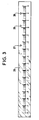
- FIG. 3 represents a possible variant of FIG. 2 in which the graduations of the N decades are inscribed on a fixed scale 26, and the range of possible measurement over a range of n decades, under the current conditions of measurement, is given by two mobile light signals 27 and 28 represented in the form of triangles in FIG. 3. And likewise, the mobile indicator needle 25 of the value of the leak in FIG. 2, is replaced in this variant of FIG. 3 by a mobile light signal 29 between signals 27 and 28 indicating the possible range of measurement. This mobile light signal 29 is also represented in the form of a triangle.
Abstract
Le dispositif comporte un ruban gradué (22) sur une étendue de N décades apte à défiler devant une fenêtre (24) s'étendant sur une largeur correspondant à n décades et une aiguille indicatrice (25) de la valeur de la fuite. Le mouvement du ruban est asservi à l'ouverture d'une vanne d'introduction de gaz vers la cellule d'analyse du détecteur de fuite et l'aiguille est asservie au flux du gaz traceur qui traverse la cellule.The device comprises a graduated ribbon (22) over a range of N decades capable of running past a window (24) extending over a width corresponding to n decades and an indicator needle (25) of the value of the leak. The movement of the ribbon is controlled by the opening of a gas introduction valve to the analysis cell of the leak detector and the needle is controlled by the flow of tracer gas which passes through the cell.
Description
On sait que dans le but de contrôler l'étanchéité d'un organe tel qu'un réservoir ou d'une installation sous vide on utilise un gaz traceur tel que l'hélium que l'on injecte dans ledit organe ou installation. Dans le cas où de tels organes présentent une fissure, l'hélium débouche de cette dernière et est envoyé dans un dispositif de mesure tel qu'un spectromètre de masse analyseur de gaz qui permet donc selon la quantité d'hélium reçue de déterminer l'importance de ladite fissure.It is known that in order to control the tightness of an organ such as a reservoir or of a vacuum installation, a tracer gas is used such as helium which is injected into said organ or installation. In the case where such organs have a crack, the helium emerges from the latter and is sent to a measuring device such as a mass spectrometer gas analyzer which therefore allows according to the quantity of helium received to determine the importance of said crack.
Un détecteur de fuites conventionnel est généralement constitué de quatre parties :
- Une première partie destinée à évacuer l'air de l'organe ou de l'installation à contrôler au moyen notamment d'une pompe primaire par exemple du type à palettes associée à des organes tels que vanne d'isolement de la pompe, vanne d'entrée d'air, manomètre de mesure de pression.
- A first part intended for evacuating the air from the member or from the installation to be controlled by means in particular of a primary pump, for example of the vane type associated with members such as pump isolation valve, d valve air inlet, pressure measurement manometer.
Une deuxième partie destinée à analyser le gaz traceur en provenance de ladite première partie et comportant donc une cellule d'analyse tel qu'un spectromètre de masse, une pompe primaire par exemple à palettes, un dispositif de pompage secondaire du type pompe à diffusion turbo-moléculaire ou ionique, un piège par exemple à azote liquide, et un manomètre de mesure de pressions.A second part intended for analyzing the tracer gas coming from said first part and therefore comprising an analysis cell such as a mass spectrometer, a primary pump, for example a vane pump, a secondary pumping device of the turbo diffusion pump type -molecular or ionic, a trap for example with liquid nitrogen, and a pressure gauge.
Une troisième partie apte à introduire le mélange gazeux à analyser ou une fraction de ce dernier dans ladite deuxième partie et comportant généralement une vanne à débit réglable.A third part capable of introducing the gaseous mixture to be analyzed or a fraction of the latter into said second part and generally comprising a valve with adjustable flow.
Enfin une quatrième partie de calcul et d'affichage des résultats donc de l'importance des fuites, par exemple au moyen d'un dispositif électronique approprié.Finally a fourth part of calculation and display of the results therefore of the importance of the leaks, for example by means of an appropriate electronic device.
Or dans les techniques conventionnelles de détection des fuites, ces dernières varient dans une gamme de valeurs étendues que l'on peut évaluer sensiblement de 10-11 à 103 atmosphère cm/seconde, ? cette gamme de valeurs étant d'ailleurs exprimée en N décades par les techniciens en matière de vide. La gamme de valeurs précédente correspond donc à 15 décades.However, in conventional leak detection techniques, these vary within a range of extended values which can be evaluated appreciably from 10-11 to 10 3 atmosphere cm / s seconds ,? this range of values is also expressed in N decades by vacuum technicians. The previous range of values therefore corresponds to 15 decades.
En conséquence, une telle étendue desdites gammes conduit les constructeurs de détecteurs de fuites à mettre en oeuvre des montages divers adaptés à la valeur des fuites à détecter.Consequently, such an extent of said ranges leads manufacturers of leak detectors to implement various assemblies adapted to the value of the leaks to be detected.
Pour fixer les idées dans le cas de fuites de faibles valeurs, de l'ordre de 10-11 à 10-5 atmosphère cm3/seconde, la totalité du flux gazeux d'hélium est dirigée vers l'analyseur, la vanne de ladite deuxième partie étant entièrement ouverte.To fix ideas in the case of leaks of low values, of the order of 10-11 to 10-5 atmosphere cm 3 / second, the entire helium gas flow is directed to the analyzer, the valve of said second part being entirely open.
Dans le cas de fuites de valeurs moyennes soit de 10-5 à 1 atmosphère cm3/seconde une partie du flux gazeux sera détournée vers la pompe primaire de la première partie du détecteur tandis que la vanne de la deuxième partie dudit détecteur ne sera que partiellement ouverte, ou remplacée par des vannes à plus faible passage gazeux.In the case of average values of leakage is of 10- 5 to 1 atmosphere cm 3 / second part of the gas flow will be diverted to the primary pump of the first portion of the sensor while the second valve portion of said sensor will be only partially open, or replaced by valves with lower gas passage.
Enfin, pour des fuites de valeurs élevées, supérieures à 1 atmosphère cm3/seconde il s'avère nécessaire de limiter le débit de la vanne de la deuxième partie par tout moyen approprié tel qu'un diaphragme, un tube capillaire ou autre, et même de remplacer ladite vanne par une membrane.Finally, for leaks of high values, greater than 1 atmosphere cm 3 / second, it proves necessary to limit the flow rate of the valve of the second part by any suitable means such as a diaphragm, a capillary tube or the like, and even to replace said valve with a membrane.
De la sorte, selon le cas, la cellule d'analyse décèle un flux d'hélium q qui la traverse, et qui correspond à la totalité ou à une partie du flux Q débouchant d'une fissure de l'organe ou installation à tester.In this way, as the case may be, the analysis cell detects a flow of helium q which passes through it, and which corresponds to all or part of the flow Q emerging from a crack in the organ or installation to be tested. .
La capacité de mesure des circuits électroniques associés à la cellule d'analyse est limitée à un nombre restreint de n décades de valeurs de fuites soit 5 à 6 au maximum.The measurement capacity of the electronic circuits associated with the analysis cell is limited to a limited number of n decades of leakage values,
Autrement dit dans les réalisations de détecteurs actuelles à nombre restreint de décades, il n'existe pas de solution permettant à l'opérateur de connaître simultanément la valeur exacte de la fuite Q à travers ladite fissure et la gamme de mesure de n décades dans les conditions instantanées de travail. Il en résulte que l'utilisateur pourra envisager une sensibilité de l'appareil de nature à déceler des fuites de l'ordre de 10-10 atmosphère cm/seconde, alors qu'en fait une pression d'entrée de 10-2 atmosphère par exemple, limitera ladite sensibilité à 10-5 atmosphère cm3/seconde.In other words in the embodiments of current detectors with a limited number of decades, there is no solution allowing the operator to simultaneously know the exact value of the leak Q through said crack and the measurement range of n decades in the instant working conditions. As a result, the user can envisage a sensitivity of the device such as to detect leaks of the order of 10 -10 atmosphere cm / second, when in fact an inlet pressure of 10 -2 atmosphere per example, will limit said sensitivity to 10 -5 cm 3 / second atmosphere.
La présente invention permet de remédier aux inconvénients cités ci-dessus en permettant à l'opérateur de connaître exactement les possibilités de son appareil.The present invention overcomes the drawbacks mentioned above by allowing the operator to know exactly the possibilities. of his device.
L'invention a pour objet un dispositif de mesure et d'affichage du taux Q de fuite pour un détecteur de fuites à gaz traceur du type comportant principalement une pompe à vide primaire apte à être connectée où non à un organe à contrôler, une vanne connectée également audit organe à contrôler et communiquant avec une cellule d'analyse maintenue sous vide par l'intermédiaire d'un groupe de pompage comprenant une pompe primaire et une pompe secondaire, ladite vanne comportant un clapet dont le degré d'ouverture est commandé par un moteur asservi à la pression régnant sensiblement à l'entrée de ladite cellule d'analyse, ce degré d'ouverture étant converti en un signal électrique transmis audit dispositif de mesure et d'affichage lui-même asservi à ladite cellule d'analyse, caractérisé en ce que ledit dispositif de mesure et d'affichage comporte un système de signalisation permettant de sélectionner et d'afficher une étendue de n décades dans une gamme de N décades et d'afficher simultanément dans cette gamme de n décades la valeur de la fuite de l'organe à contrôler.The subject of the invention is a device for measuring and displaying the leakage rate Q for a tracer gas leak detector of the type mainly comprising a primary vacuum pump capable of being connected or not to a member to be controlled, a valve also connected to said member to be controlled and communicating with an analysis cell maintained under vacuum by means of a pumping group comprising a primary pump and a secondary pump, said valve comprising a valve whose degree of opening is controlled by a motor slaved to the pressure prevailing substantially at the input of said analysis cell, this degree of opening being converted into an electrical signal transmitted to said measurement and display device itself slaved to said analysis cell, characterized in that said measurement and display device comprises a signaling system making it possible to select and display a range of n decades in a range of N decades and to display simultaneously in this range of n decades the value of the leak of the organ to be checked.
Selon une réalisation préférée de l'invention, ledit système de signalisation comporte simultanément un ruban gradué sur une étendue de N décades apte à défiler devant une fenêtre s'étendant sur une longueur correspondant à n décades, et une aiguille indicatrice.According to a preferred embodiment of the invention, said signaling system simultaneously comprises a tape graduated over a range of N decades capable of scrolling past a window extending over a length corresponding to n decades, and an indicator hand.
Dans une variante de réalisation, le système de signalisation comporte un dispositif lumineux indiquant la portion sélectionnée des n décades de travail parmi l'étendue des N décades, et indiquant simultanément par des moyens lumineux la valeur de la fuite dans cette gamme sélectionée.In an alternative embodiment, the signaling system comprises a light device indicating the selected portion of the n decades of work from the range of the N decades, and simultaneously indicating by light means the value of the leak in this selected range.
D'autres caractéristiques et avantages de l'invention ressortiront de la description qui suit donnée à titre d'exemple purement illustratif mais nullement limitatif en référence aux dessins annexés dans lesquels :
- La figure 1 représente schématiquement un détecteur de fuites auquel s'applique le dispositif selon l'invention.
- La figure 2 représente le dispositif d'affichage faisant partie du dispositif selon l'invention.
- La figure 3 représente une variante de la figure 2.
- FIG. 1 schematically represents a leak detector to which the device according to the invention applies.
- FIG. 2 represents the display device forming part of the device according to the invention.
- FIG. 3 represents a variant of FIG. 2.
Sur la figure 1, la référence 1 est affectée à un organe par exemple un réservoir dont l'étanchéité doit être contrôlée.In FIG. 1, the
Ce réservoir est connecté à une pompe primaire à palettes 2 par l'intermédiaire d'une conduite 3, une vanne 17 étant intercalée sur la conduite 3 dans le but d'isoler éventuellement la pompe 2. Sur cette conduite 3 sont branchés une vanne d'entrée d'air 4 ainsi qu'un manomètre 5.This reservoir is connected to a
La conduite 3 communique par l'intermédiaire d'une conduite 6 avec une vanne 7 d'introduction de gaz vers la cellule d'analyse, qui sera plus particulièrement décrite par ailleurs.
Cette vanne 7 communique au moyen d'une conduite 8 avec un piège à azote liquide 9 au niveau duquel sont connectés une cellule d'analyse 10 tel qu'un spectromètre de masse et un manomètre 11. En outre une conduite 12 met en relation ledit piège 9 avec un dispositif de pompage secondaire 13 lui-même connecté avec une pompe primaire à palettes 14, et celà au moyen de la canalisation 15.This
Le dispositif de pompage secondaire 13 est une pompe à diffusion, une pompe turbomoléculaire ou une pompe ionique.The
La référence 16 désigne un dispositif électronique de calcul et d'affichage des résultats de mesures de détection.
Par ailleurs, la vanne 7 est du type vanne motorisée c'est-à-dire qu'elle comporte un clapet à ouverture progressive dont le profil permet sa mise en oeuvre pour des pressions en amont de l'ordre de 10-4 à 1 mbar. Le déplacement dudit clapet est commandé par un moteur électrique ou pneumatique schématisé en 20 et asservi à la pression du manomètre 11, de telles fonctions étant matérialisées par les lignes en traits tiretés L1 et L2 respectivement. De plus, le déplacement du clapet entraîne un déplacement concomittant du curseur d'un potentiomètre (non représenté) transmettant de la sorte au dispositif électronique 16 un signal représentatif du degré d'ouverture de la vanne 7 une telle fonction étant matérialisée par la ligne L3.Furthermore, the
Enfin, la ligne L4 montre que le dispositif électronique 16 est également asservi à la cellule d'analyse 10.Finally, line L 4 shows that the
On voit donc en conséquence que ledit dispositif électronique 16 reçoit des informations correspondant au degré d'ouverture ou de fermeture de la vanne 7. L'information ainsi délivrée permet de déplacer par l'intermédiaire de rouleaux 23 un ruban 22 (figure 2) portant une graduation logarithmique sur une étendue de N décades, allant par exemple de 10-12 à 103 atmosphère cm3/seconde, donc correspondant aux performances limites du détecteur. Sur la figure 2, les chiffres représentés sur la bande 22 constituent les différentes puissances de dix.It can therefore be seen therefore that said
Ledit ruban 22 défile devant une fenêtre de lecture 24 qui ne laisse apparaître que le nombre n de décades correspondant à la gamme de lecture possible dans les conditions opératoires, soit 4 à 5 dans l'exemple représenté. L'opérateur est donc ainsi renseigné sur les valeurs minimale et maximale qu'il peut mesurer dans les conditions opérationnelles de l'essai. En outre, ladite fenêtre 24 comporte une aiguille mobile 25 dont la position est asservie, par un dispositif à asservissement potentiométrique, à la sortie de la cellule d'analyse 10 par l'intermédiaire du dispositif 16 donc au flux d'hélium q qui traverse la cellule, ce flux étant amplifié par un amplificateur logarithmique. Cette aiguille 25 affiche donc la valeur exacte de la fuite Q dans la gamme n de mesure apparaissant dans la fenêtre 24.Said
On voit donc que le dispositif selon l'invention permet d'indiquer à l'opérateur, la valeur exacte du flux Q donc de la fuite de l'organe testé, ainsi que la gamme de mesure possible dans une plage des n décades sélectionnées parmi les N décades telles que définies dans ce qui précède, et cela quelles que soient les pressions d'entrée du flux gazeux.It can therefore be seen that the device according to the invention makes it possible to indicate to the operator, the exact value of the flow Q therefore of the leakage of the organ tested, as well as the range of measurement possible in a range of n decades selected from the N decades as defined in the above, and this whatever the inlet pressures of the gas flow.
Un tel dispositif permet de clarifier l'interprétation des signaux délivrés par la cellule d'analyse.Such a device makes it possible to clarify the interpretation of the signals delivered by the analysis cell.
Il trouve des applications avantageuses dans le domaine des détections de fuites par gaz traceur tel que l'hélium ou l'hydrogène.It finds advantageous applications in the field of leak detection by tracer gas such as helium or hydrogen.
La figure 3 représente une variante possible de la figure 2 dans laquelle les graduations des N décades sont inscrites sur une échelle fixe 26, et la gamme de mesure possible sur une étendue de n décades, dans les conditions actuelles de la mesure, est donnée par deux signaux lumineux mobiles 27 et 28 représentés sous forme de triangles sur la figure 3. Et de même, l'aiguille indicatrice mobile 25 de la valeur de la fuite de la figure 2, est remplacée sur cette variante de la figure 3 par un signal lumineux mobile 29 entre les signaux 27 et 28 indiquant la plage possible de mesure. Ce signal lumineux mobile 29 est également représenté sous la forme d'un triangle.FIG. 3 represents a possible variant of FIG. 2 in which the graduations of the N decades are inscribed on a
Sur cette figure, les chiffres indiqués sur l'échelle fixe 26 représentent les différentes puissances de 10 comme sur l'échelle selon la figure 2.In this figure, the figures indicated on the
Claims (2)
Applications Claiming Priority (2)
| Application Number | Priority Date | Filing Date | Title |
|---|---|---|---|
| FR8214699 | 1982-08-27 | ||
| FR8214699A FR2532424A1 (en) | 1982-08-27 | 1982-08-27 | DEVICE FOR MEASURING AND DISPLAYING THE LEAKAGE RATE Q FOR A GAS LEAK DETECTOR |
Publications (2)
| Publication Number | Publication Date |
|---|---|
| EP0103771A1 true EP0103771A1 (en) | 1984-03-28 |
| EP0103771B1 EP0103771B1 (en) | 1987-09-09 |
Family
ID=9277082
Family Applications (1)
| Application Number | Title | Priority Date | Filing Date |
|---|---|---|---|
| EP83108295A Expired EP0103771B1 (en) | 1982-08-27 | 1983-08-23 | Leak detector of the gas tracer type having a device for measuring and indicating the leak rate q |
Country Status (5)
| Country | Link |
|---|---|
| US (1) | US4510792A (en) |
| EP (1) | EP0103771B1 (en) |
| JP (1) | JPS5960238A (en) |
| DE (1) | DE3373536D1 (en) |
| FR (1) | FR2532424A1 (en) |
Families Citing this family (18)
| Publication number | Priority date | Publication date | Assignee | Title |
|---|---|---|---|---|
| FR2561771B1 (en) * | 1984-03-23 | 1986-06-27 | Cit Alcatel | METHOD FOR DEPOLLUTING A HELIUM LEAK DETECTOR AND DEVICE FOR CARRYING OUT THIS METHOD |
| US4735084A (en) * | 1985-10-01 | 1988-04-05 | Varian Associates, Inc. | Method and apparatus for gross leak detection |
| FR2604522B1 (en) * | 1986-09-26 | 1989-06-16 | Cit Alcatel | PLOTTERY GAS LEAK DETECTION SYSTEM AND METHOD OF USE |
| JP2507023Y2 (en) * | 1990-05-26 | 1996-08-14 | 松下電工株式会社 | Deku corner corner accessory mounting structure |
| US5168747A (en) * | 1990-11-26 | 1992-12-08 | Westinghouse Electric Corp. | System and method for locating leaks in steam turbine systems |
| JPH0674855A (en) * | 1992-07-08 | 1994-03-18 | Hitachi Bill Shisetsu Eng Kk | Vacuum leakage detection method and device |
| US5625141A (en) * | 1993-06-29 | 1997-04-29 | Varian Associates, Inc. | Sealed parts leak testing method and apparatus for helium spectrometer leak detection |
| DE4408877A1 (en) * | 1994-03-16 | 1995-09-21 | Leybold Ag | Test gas leak detector |
| US5746435A (en) * | 1994-09-30 | 1998-05-05 | Arbuckle; Donald P. | Dual seal barrier fluid leakage control method |
| FI970665A0 (en) | 1996-04-15 | 1997-02-17 | Espoon Paineilma Oy | Foerfarande Foer identifier av laeckage i en foerpackning isynnerhet livsmedels- och laekemedelsfoerpackning samt foerbaettrande av haollbarheten hos vaetskeformiga livsmedel vilka aer foerpackade i aseptiska kartongfoerpackningar |
| FR2761776B1 (en) * | 1997-04-03 | 1999-07-23 | Alsthom Cge Alcatel | GAS LEAK DETECTOR |
| DE19735250A1 (en) * | 1997-08-14 | 1999-02-18 | Leybold Vakuum Gmbh | Method to operate helium leak detector |
| WO2000009956A2 (en) * | 1998-08-17 | 2000-02-24 | Arbuckle Donald P | Integrated barrier fluid sealing apparatus with visual volume indicator |
| US6314793B1 (en) * | 1999-09-28 | 2001-11-13 | Gas Research Institute | Test device for measuring chemical emissions |
| US6885967B2 (en) * | 2003-06-23 | 2005-04-26 | Honeywell International Inc. | Spacecraft depressurization analyzer |
| US7764186B2 (en) * | 2007-04-23 | 2010-07-27 | J And N Enterprises Inc. | Gas sensing method and instrument therefor |
| KR101010674B1 (en) * | 2008-08-28 | 2011-01-24 | 삼성전기주식회사 | Ink suction apparatus |
| US11035818B2 (en) * | 2014-08-15 | 2021-06-15 | Roche Diabetes Care, Inc. | Blood glucose meter with low cost user interface having programmed graphic indicators |
Citations (5)
| Publication number | Priority date | Publication date | Assignee | Title |
|---|---|---|---|---|
| GB1054059A (en) * | 1962-11-14 | 1900-01-01 | ||
| FR1428585A (en) * | 1965-01-06 | 1966-02-18 | Jaeger Ets Ed | Further development of measuring instruments with rectilinear reading scales |
| US3416359A (en) * | 1966-07-01 | 1968-12-17 | Texas Instruments Inc | Method and apparatus for testing hermetically sealed transistor devices |
| FR2313663A1 (en) * | 1975-06-04 | 1976-12-31 | Portescap | Measuring instrument with linear scale - has at least two measurement ranges and selection device switching over measurement circuit and positioning single scale |
| DE2713580A1 (en) * | 1977-03-28 | 1978-10-05 | Leybold Heraeus Gmbh & Co Kg | Leak detector using test gas - has set of parallel pipes and valves of different sizes and is connected to vacuum pump |
Family Cites Families (8)
| Publication number | Priority date | Publication date | Assignee | Title |
|---|---|---|---|---|
| GB1047204A (en) * | 1964-05-26 | 1900-01-01 | ||
| US3327521A (en) * | 1964-10-26 | 1967-06-27 | Nat Res Corp | Leak detector and vacuum pumping station |
| FR1474137A (en) * | 1966-02-08 | 1967-03-24 | Alcatel Sa | Easily transportable helium leak detector |
| US3690151A (en) * | 1968-07-25 | 1972-09-12 | Norton Co | Leak detector |
| US3626760A (en) * | 1969-07-16 | 1971-12-14 | Varian Associates | Leak detection cyclic pumping control |
| US3968675A (en) * | 1974-06-07 | 1976-07-13 | Varian Associates | Method and apparatus for preparing a mass spectrometer leak detector system for operation |
| JPS593790B2 (en) * | 1975-06-20 | 1984-01-26 | 日本電気株式会社 | FFT Ensanshiyori Sochi |
| FR2475728A1 (en) * | 1980-02-11 | 1981-08-14 | Cit Alcatel | HELIUM LEAK DETECTOR |
-
1982
- 1982-08-27 FR FR8214699A patent/FR2532424A1/en active Granted
-
1983
- 1983-08-23 EP EP83108295A patent/EP0103771B1/en not_active Expired
- 1983-08-23 DE DE8383108295T patent/DE3373536D1/en not_active Expired
- 1983-08-24 US US06/525,902 patent/US4510792A/en not_active Expired - Fee Related
- 1983-08-25 JP JP58155680A patent/JPS5960238A/en active Granted
Patent Citations (5)
| Publication number | Priority date | Publication date | Assignee | Title |
|---|---|---|---|---|
| GB1054059A (en) * | 1962-11-14 | 1900-01-01 | ||
| FR1428585A (en) * | 1965-01-06 | 1966-02-18 | Jaeger Ets Ed | Further development of measuring instruments with rectilinear reading scales |
| US3416359A (en) * | 1966-07-01 | 1968-12-17 | Texas Instruments Inc | Method and apparatus for testing hermetically sealed transistor devices |
| FR2313663A1 (en) * | 1975-06-04 | 1976-12-31 | Portescap | Measuring instrument with linear scale - has at least two measurement ranges and selection device switching over measurement circuit and positioning single scale |
| DE2713580A1 (en) * | 1977-03-28 | 1978-10-05 | Leybold Heraeus Gmbh & Co Kg | Leak detector using test gas - has set of parallel pipes and valves of different sizes and is connected to vacuum pump |
Also Published As
| Publication number | Publication date |
|---|---|
| DE3373536D1 (en) | 1987-10-15 |
| FR2532424B1 (en) | 1984-12-28 |
| FR2532424A1 (en) | 1984-03-02 |
| EP0103771B1 (en) | 1987-09-09 |
| JPH0263174B2 (en) | 1990-12-27 |
| JPS5960238A (en) | 1984-04-06 |
| US4510792A (en) | 1985-04-16 |
Similar Documents
| Publication | Publication Date | Title |
|---|---|---|
| EP0103771B1 (en) | Leak detector of the gas tracer type having a device for measuring and indicating the leak rate q | |
| US9632067B2 (en) | Leak detector | |
| CA2434360C (en) | Product leak testing | |
| US6314793B1 (en) | Test device for measuring chemical emissions | |
| US3924442A (en) | Pollutant variation correcting system | |
| JP2635587B2 (en) | Device for calibrating the detector of the leak inspection device | |
| JPH10104037A (en) | Measuring apparatus for exhaust gas | |
| JP2018533741A (en) | Leak detection using oxygen | |
| EP0033945B1 (en) | Helium-type leak detector | |
| US3939695A (en) | Apparatus for detecting leaks | |
| FR2616226A1 (en) | MOISTURE COMPENSATION DEVICE FOR A PHOTO-IONIZATION DETECTOR, AND APPARATUS FOR IMPLEMENTING SAME | |
| US4348887A (en) | Apparatus for determining the effects of dilution and/or diffusion on the gaseous components of a gas flow | |
| US3825756A (en) | Calibration device for a gas analyzer | |
| CA1265357A (en) | Method and a device for detecting leakage of a tube section | |
| JP3166859B2 (en) | Vacuum / leakage inspection equipment for test gas leakage inspection using light gas | |
| US11199467B2 (en) | Device and method for distinguishing a test gas escaping from a leak from interfering gas | |
| EP0070341B1 (en) | Helium leak detector | |
| JP4447266B2 (en) | Exhaust gas flow measuring device and exhaust gas measuring system using the same | |
| RU2778833C2 (en) | Device and method for distinguishing span gas coming out of leak from perturbing gas | |
| US4100790A (en) | Electronic orsat for gas analysis | |
| US20230204447A1 (en) | Sniffing gas leak detector with hand probe | |
| JPH08254523A (en) | Measuring device and method for measuring oxygen permeability of sample | |
| FR2522147A1 (en) | Measuring gas-air mixture leakage from closed systems - using pressure change and time for reaching conc. equality | |
| SU858430A1 (en) | Device for adjusting discontinuities | |
| Park | Aids for the Analyst-Semimicro Gas Permeability Apparatus for Sheet Material |
Legal Events
| Date | Code | Title | Description |
|---|---|---|---|
| PUAI | Public reference made under article 153(3) epc to a published international application that has entered the european phase |
Free format text: ORIGINAL CODE: 0009012 |
|
| AK | Designated contracting states |
Designated state(s): DE FR GB IT NL SE |
|
| 17P | Request for examination filed |
Effective date: 19840925 |
|
| 17Q | First examination report despatched |
Effective date: 19860124 |
|
| RAP1 | Party data changed (applicant data changed or rights of an application transferred) |
Owner name: ALCATEL |
|
| R17C | First examination report despatched (corrected) |
Effective date: 19860623 |
|
| RAP1 | Party data changed (applicant data changed or rights of an application transferred) |
Owner name: ALCATEL CIT |
|
| GRAA | (expected) grant |
Free format text: ORIGINAL CODE: 0009210 |
|
| AK | Designated contracting states |
Kind code of ref document: B1 Designated state(s): DE FR GB IT NL SE |
|
| REF | Corresponds to: |
Ref document number: 3373536 Country of ref document: DE Date of ref document: 19871015 |
|
| ITF | It: translation for a ep patent filed |
Owner name: JACOBACCI & PERANI S.P.A. |
|
| GBT | Gb: translation of ep patent filed (gb section 77(6)(a)/1977) | ||
| PLBE | No opposition filed within time limit |
Free format text: ORIGINAL CODE: 0009261 |
|
| STAA | Information on the status of an ep patent application or granted ep patent |
Free format text: STATUS: NO OPPOSITION FILED WITHIN TIME LIMIT |
|
| 26N | No opposition filed | ||
| PGFP | Annual fee paid to national office [announced via postgrant information from national office to epo] |
Ref country code: SE Payment date: 19910521 Year of fee payment: 9 |
|
| PGFP | Annual fee paid to national office [announced via postgrant information from national office to epo] |
Ref country code: FR Payment date: 19910530 Year of fee payment: 9 |
|
| PGFP | Annual fee paid to national office [announced via postgrant information from national office to epo] |
Ref country code: GB Payment date: 19910612 Year of fee payment: 9 Ref country code: DE Payment date: 19910612 Year of fee payment: 9 |
|
| ITTA | It: last paid annual fee | ||
| PGFP | Annual fee paid to national office [announced via postgrant information from national office to epo] |
Ref country code: NL Payment date: 19910831 Year of fee payment: 9 |
|
| PG25 | Lapsed in a contracting state [announced via postgrant information from national office to epo] |
Ref country code: GB Effective date: 19920823 |
|
| PG25 | Lapsed in a contracting state [announced via postgrant information from national office to epo] |
Ref country code: SE Effective date: 19920824 |
|
| PG25 | Lapsed in a contracting state [announced via postgrant information from national office to epo] |
Ref country code: NL Effective date: 19930301 |
|
| NLV4 | Nl: lapsed or anulled due to non-payment of the annual fee | ||
| GBPC | Gb: european patent ceased through non-payment of renewal fee |
Effective date: 19920823 |
|
| PG25 | Lapsed in a contracting state [announced via postgrant information from national office to epo] |
Ref country code: FR Effective date: 19930430 |
|
| PG25 | Lapsed in a contracting state [announced via postgrant information from national office to epo] |
Ref country code: DE Effective date: 19930501 |
|
| REG | Reference to a national code |
Ref country code: FR Ref legal event code: ST |
|
| EUG | Se: european patent has lapsed |
Ref document number: 83108295.3 Effective date: 19930307 |