EP0103522B1 - Fahrbare Sprühvorrichtung für eine Flüssigkeit zur Behandlung von Pflanzen - Google Patents
Fahrbare Sprühvorrichtung für eine Flüssigkeit zur Behandlung von Pflanzen Download PDFInfo
- Publication number
- EP0103522B1 EP0103522B1 EP83401774A EP83401774A EP0103522B1 EP 0103522 B1 EP0103522 B1 EP 0103522B1 EP 83401774 A EP83401774 A EP 83401774A EP 83401774 A EP83401774 A EP 83401774A EP 0103522 B1 EP0103522 B1 EP 0103522B1
- Authority
- EP
- European Patent Office
- Prior art keywords
- articulated
- ball joint
- support member
- upper side
- framework member
- Prior art date
- Legal status (The legal status is an assumption and is not a legal conclusion. Google has not performed a legal analysis and makes no representation as to the accuracy of the status listed.)
- Expired
Links
Images
Classifications
-
- A—HUMAN NECESSITIES
- A01—AGRICULTURE; FORESTRY; ANIMAL HUSBANDRY; HUNTING; TRAPPING; FISHING
- A01M—CATCHING, TRAPPING OR SCARING OF ANIMALS; APPARATUS FOR THE DESTRUCTION OF NOXIOUS ANIMALS OR NOXIOUS PLANTS
- A01M7/00—Special adaptations or arrangements of liquid-spraying apparatus for purposes covered by this subclass
- A01M7/005—Special arrangements or adaptations of the spraying or distributing parts, e.g. adaptations or mounting of the spray booms, mounting of the nozzles, protection shields
- A01M7/0053—Mounting of the spraybooms
-
- Y—GENERAL TAGGING OF NEW TECHNOLOGICAL DEVELOPMENTS; GENERAL TAGGING OF CROSS-SECTIONAL TECHNOLOGIES SPANNING OVER SEVERAL SECTIONS OF THE IPC; TECHNICAL SUBJECTS COVERED BY FORMER USPC CROSS-REFERENCE ART COLLECTIONS [XRACs] AND DIGESTS
- Y10—TECHNICAL SUBJECTS COVERED BY FORMER USPC
- Y10T—TECHNICAL SUBJECTS COVERED BY FORMER US CLASSIFICATION
- Y10T74/00—Machine element or mechanism
- Y10T74/20—Control lever and linkage systems
- Y10T74/20207—Multiple controlling elements for single controlled element
Definitions
- the invention relates to a mobile device for spraying a plant treatment liquid.
- a mobile device for spraying which is described in the European patent application EP-A1-0 085 597 belonging to the state of the art within the meaning of article 54, paragraph 3, of the convention on the grant of European patents, and which is illustrated in particular in its figure 5, comprises a support frame carried by a vehicle, tractor or towed, in a position perpendicular to the direction of advance of the vehicle, a rectangular frame, suspended from the support frame by means of a ball joint, carried by the support frame, and an articulated link, interposed between the ball joint and the middle of the upper side of the rectangular frame.
- at least one rigid member of adjustable length such as a jack, is interposed between the ball joint or the support frame, integral with the vehicle, and a point of the rectangular frame, spaced from the corresponding articulation of the link.
- the adjustment of the length of the rigid member makes it possible to maintain, in service, the lateral sides of the rectangular frame, always parallel to the longitudinal plane of symmetry of the vehicle and, consequently, to maintain the lateral spray bars, which are fixed to the lateral sides of said rectangular frame, substantially perpendicular to the longitudinal plane of symmetry of the vehicle.
- the arrangement which has just been recalled makes it possible, by an appropriate adjustment of the length of the rigid member, to constantly maintain the lateral spraying booms substantially parallel to the line of greatest slope of the ground, and, consequently, to equal distance from it, at all points of the spray bars.
- This arrangement therefore makes it possible to carry out a spraying on plants growing on a slope, in conditions of efficiency and regularity as good as for plants growing on a substantially horizontal ground.
- the patent application in the United Kingdom No. 2014834 describes a mobile device for spraying a plant treatment liquid comprising at least one spraying boom which is mounted to oscillate below a substantially horizontal axis and parallel to the longitudinal direction of advance of the vehicle carrying said ramp.
- This known arrangement makes it possible, to a large extent, to avoid, thanks to the inertia of the spraying boom, that the latter follows all the vehicle's rolling oscillations, and that it therefore too often departs from parallelism. on the horizontal ground, which would affect the regularity of the spreading.
- the main object of the present invention is to remedy the drawbacks of these known devices.
- the mobile device for spraying a plant treatment liquid comprises a support element, carried by a vehicle, tractor or towed, in a position perpendicular to the direction of advance of the vehicle, a rectangular frame carrying spray bars and suspended from the support element by means of a ball joint carried by the support element, and an articulated link, interposed between the ball joint and the middle of the upper side of the 'rectangular frame element, at least one rigid member of adjustable length, such as a jack, being interposed between the ball joint and a point of the rectangular frame element, spaced from the corresponding articulation of the rod, apparatus in which the ball joint is mounted on the upper part of a member, the lower part of which is articulated on the upper side of the support element, and in which an additional rigid member of adjustable length, such as a jack, has its ends articulated respectively on the support element and on the articulated member, the lengths of the rigid members being adjusted in service so that the lateral sides of the rectangular frame element are always parallel to the longitudinal plane of symmetry of the vehicle
- the two lateral spraying booms are kept always equidistant from the longitudinal plane of symmetry of the vehicle, whether the latter progresses on horizontal terrain or on inclined terrain, transverse to its lines of greatest slope. , which avoids, in the latter case, any loss of spraying liquid as well as the absence of spraying on a strip of land, contiguous to the running track of the vehicle.
- the distance between the upper and lower joints of the articulated member is substantially equal to the length of the articulated link. Therefore, the upper edges of the support frame, integral with the vehicle, and the rectangular frame, movable relative to this support frame, are maintained, in service, constantly parallel to each other, but furthermore they are kept at approximately the same distance from the ground. As a result, the lateral spray bars, which are fixed to the rectangular frame, are themselves always kept at the same distance from the ground, whether the latter is horizontal or inclined, which further promotes the regularity and efficiency of the spraying carried out.
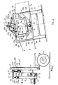
- Figure 1 is an elevational view in partial section of this embodiment, also showing the rear axle of the carrier vehicle.
- FIG. 2 is a simplified view in the direction of the arrow II in FIG. 1, in the case where the carrier vehicle progresses perpendicular to the lines of greatest slope of an inclined terrain.
- 1 designates the axle, single or rear, of the carrier vehicle, the wheels of which are designated by 1a and 1b.
- 2 designates the rear part of the chassis of the carrier vehicle, which can be an agricultural tractor, or a trailer, in particular a trailer carrying a large reservoir - not shown - of plant treatment liquid.
- a support frame, substantially rectangular 4, for example made of welded metal sections, is slidably mounted on uprights such as 3a (not shown in FIG. 2), which are themselves welded to the rear part 2 of the vehicle chassis, perpendicular to its axle 1.
- a jack allows the frame 4 to be moved vertically on the uprights such as 3a.
- An articulated parallelogram, 22, formed by three links 22A to 22C, has its lateral sides, 22B and 22C, of the same length, articulated, by their lower ends, at two points pB and pC on the upper side, 4A, of the support frame 4, which are equidistant from the longitudinal plane of symmetry P (FIG. 2) of the vehicle.
- a spherical bearing 10 is mounted in the middle of the upper side, 22A, of the articulated parallelogram 22.
- the side 22A of the articulated parallelogram 22 is integral with the housing of the bearing 10, including the ball joint is itself secured to one end of a bracket 12, on the other end of which is fixed the upper end of a vertical link 19.
- the lower end, 19a, of the link 19 is itself even articulated in the middle of the upper side 5A of a rectangular frame 5, the plane of which is parallel to that of the support frame 4.
- a first rigid member of adjustable length, in particular a jack 23, has its articulated ends, one, at 23a, at a point on the upper side, 4A, of the support frame 4, more distant from its medium than the joint pC , in particular near the left end, in FIG. 2, of said upper side 4A, while the other end of the jack 23, in particular of its rod, is articulated, at 23b, on the articulated parallelogram 22, in particular on its lateral side 22C.
- a second rigid member, of adjustable length, in particular a second jack 24, also has its articulated ends, one, at 24a, at a point on the upper side 5A of the rectangular frame 5, spaced from its middle 19a, and in particular close to the right end of said upper side 5A, while the other end of the jack 24, and in particular of its rod, is articulated, at 24b, at an intermediate point of the rod 19.
- Two lateral spray bars, 6a and 6b which can be of any type, are fixed to the lateral sides, 5B and 5C, of the rectangular frame 5, for example perpendicular to its lateral sides, as visible in FIG. 2.
- Des guy wires, 8a and 8b can be provided to support the ends of the spray bars 6a and 6b.
- rollers 12a and 12b are mounted, for example in yokes, so as to rotate freely.
- the rollers 12a and 12b can roll on suitable rolling surfaces, 5a and 5b (FIG. 2), mounted on the rear face of said rectangular frame 5 and secured, for example, to its lateral sides.
- the rollers 12a and 12b, or at least their rims, are preferably made of an elastic material, ensuring good shock absorption, for example rubber, elastomer, synthetic materials, etc.
- a helical spring 13 is compressed between a plate-shaped element, 5c, integral with the lower side of the rectangular frame 5, on the one hand, and on the other hand, a pair of nut and counter nut, 14, screwed onto one end of a threaded rod, 15; the other end of the rod 15 freely crosses the plate 5c and extends to near the rectangular frame 4, where said end of the rod 15 carries an idler roller 16; it can roll, practically without axial displacement, in a raceway 17, which, in the embodiment considered, is materialized by a U-section angle iron, a wing of which is for example welded near the lower edge of the frame rectangular 4, while its other wing, substantially parallel to the plane of the frame 4, prevents said roller 16 from escaping.
- the raceway 17 can be flat or curved in an arc, centered on the horizontal axis ⁇ of the ball 10.
- the lengths outputs of the rods of the cylinders 23 and 24 are adjusted, according to the present invention, as follows: the cylinder 23 is adjusted so as to tilt the lateral side 22C of the articulated parallelogram 22 by an angle 6 less than 90 degrees, on the upper side, 4A, of the support frame 4, which has the effect of moving the spherical bearing 10 of the length 122-cos 6 to the right of FIG. 2, designating by 122 the lengths of the two lateral sides of the parallelogram articulated 22.
- the equilibrium position of the pendulum system must also be such that, according to the present invention, the spraying booms 6a and 6b are parallel to the line of greatest slope L, so, therefore, that the upper side, 5A , of the rectangular frame 5.
- V the vertical which, in this position of equilibrium of the pendulum system, illustrated in FIG. 2, passes both through the center of the ball bearing 10 and through the center of gravity G of the pendulum assembly, said vertical V makes, with the plane P, an angle ⁇ equal to the slope of the line L, so that the angle ⁇ p is defined by the condition: where D is the distance from G to the middle of side 5A of the rectangular frame 5.
- the present invention is not limited to the embodiment described above. It encompasses all of its variants, some of which will be indicated, only by way of examples.
- the articulated parallelogram 22 could be replaced by a second link, on the upper end of which the ball bearing 10 would be mounted, its lower end being on the other hand articulated towards the middle of the upper side, 4A, of the support frame 4.
- the second link would advantageously have the same length as the first link, 19.
- the present invention is also applicable to a mobile device comprising a single sprayer boom.
- the cylinders 23 and 24 could be replaced by other rigid members, of adjustable length. Hydraulic cylinders have the advantage, however, of being able to be remotely controlled from the cabin of the carrier vehicle or tractor.
- the adjustments of their respective lengths could also be easily automated by means of a computer, digital or analog, determining the values of the angles 0 and ⁇ p using the relations (1) and (2) previously indicated, from the slope ⁇ of the ground in the direction transverse to that of the movement of the mobile device, this slope being for example measured and transmitted to the computer by known automatic means.
Landscapes
- Life Sciences & Earth Sciences (AREA)
- Engineering & Computer Science (AREA)
- Insects & Arthropods (AREA)
- Pest Control & Pesticides (AREA)
- Wood Science & Technology (AREA)
- Zoology (AREA)
- Environmental Sciences (AREA)
- Catching Or Destruction (AREA)
- Special Spraying Apparatus (AREA)
Claims (11)
Applications Claiming Priority (2)
| Application Number | Priority Date | Filing Date | Title |
|---|---|---|---|
| FR8215421A FR2532817B2 (fr) | 1982-09-13 | 1982-09-13 | Appareil mobile pour la pulverisation d'un liquide de traitement des plantes |
| FR8215421 | 1982-09-13 |
Publications (2)
| Publication Number | Publication Date |
|---|---|
| EP0103522A1 EP0103522A1 (de) | 1984-03-21 |
| EP0103522B1 true EP0103522B1 (de) | 1986-03-05 |
Family
ID=9277388
Family Applications (1)
| Application Number | Title | Priority Date | Filing Date |
|---|---|---|---|
| EP83401774A Expired EP0103522B1 (de) | 1982-09-13 | 1983-09-12 | Fahrbare Sprühvorrichtung für eine Flüssigkeit zur Behandlung von Pflanzen |
Country Status (4)
| Country | Link |
|---|---|
| US (1) | US4529129A (de) |
| EP (1) | EP0103522B1 (de) |
| DE (1) | DE3362444D1 (de) |
| FR (1) | FR2532817B2 (de) |
Families Citing this family (17)
| Publication number | Priority date | Publication date | Assignee | Title |
|---|---|---|---|---|
| CA1259964A (en) * | 1985-01-21 | 1989-09-26 | Grant Fletcher | Self-levelling boom arrangement for an agricultural material distribution device |
| DD288087A5 (de) * | 1986-09-10 | 1991-03-21 | Institut Fuer Pflanzenschutzforschung Der Adl,De | Vorrichtung zur regelung der bodenparallelen auslegerlage an pflanzenschutzmaschinen |
| DK188788A (da) * | 1988-04-07 | 1989-10-08 | Dems Eng | Ophaeng til sproejtebom |
| FR2654574B1 (fr) * | 1989-11-21 | 1992-05-22 | Pasquini Daniel | Dispositif stabilisateur de montage d'un outil agricole de largeur importante sur un appareil porteur. |
| NL9200936A (nl) * | 1992-05-27 | 1993-12-16 | Greenland Nieuw Vennep Bv | Inrichting voor het verspuiten of sproeien van een vloeistof over het land. |
| US5375767A (en) * | 1993-09-07 | 1994-12-27 | Hardi Inc | Cushion suspension system for agricultural boom |
| JP3609424B2 (ja) * | 1996-09-06 | 2005-01-12 | 株式会社マルナカ製作所 | 芝生用潅注装置 |
| FR2779031B1 (fr) * | 1998-06-02 | 2004-12-03 | Exel Ind | Ensemble de rampe pendulaire, notamment pour engin de pulverisation agricole, equipe d'un dispositif de correction d'inclinaison |
| FR2786979B1 (fr) * | 1998-12-15 | 2001-02-23 | Regero Sa | Perfectionnement aux generateurs de vapeur montes sur un engin mobile, utilisables par exemple pour alimenter un ou plusieurs coffres de desinfection des sols par la vapeur |
| FR2871654B1 (fr) * | 2004-06-21 | 2006-08-18 | Exel Ind | Ensemble de rampe pendulaire, et pulverisateur equipe d'un tel ensemble |
| US7861793B2 (en) * | 2004-07-26 | 2011-01-04 | Richard Murphy | Stabilising and release system for and boom holding and positioning system for an agricultural apparatus |
| FR2888723B1 (fr) * | 2005-07-19 | 2008-05-02 | Exel Ind Sa | Ensemble de rampe de pulverisation, et pulverisateur agricole equipe d'un tel ensemble de rampe |
| GB2457388B8 (en) * | 2005-07-26 | 2025-06-18 | Murphy Richard | A boom holding and positioning system for an agricultural apparatus |
| IT1396673B1 (it) * | 2009-10-21 | 2012-12-14 | Caffini Spa | Barra di aspersione di prodotti per l'agricoltura |
| FR2993140B1 (fr) * | 2012-07-12 | 2014-07-18 | Exel Ind | Dispositif de suspension pendulaire de rampe de pulverisation pour engin agricole |
| RU169798U1 (ru) * | 2016-05-20 | 2017-04-03 | Николай Николаевич Краховецкий | Опрыскиватель штанговый |
| US10035451B2 (en) | 2016-10-28 | 2018-07-31 | Cnh Industrial America Llc | Agricultural applicator attachment system |
Citations (1)
| Publication number | Priority date | Publication date | Assignee | Title |
|---|---|---|---|---|
| EP0085597A1 (de) * | 1982-01-29 | 1983-08-10 | Tecnoma | Fahrbare Sprühvorrichtung für eine Flüssigkeit zur Behandlung von Pflanzen |
Family Cites Families (8)
| Publication number | Priority date | Publication date | Assignee | Title |
|---|---|---|---|---|
| US3223330A (en) * | 1964-06-25 | 1965-12-14 | Plante Oscar W La | Spray boom leveler apparatus |
| DE1607387A1 (de) * | 1967-04-19 | 1969-10-02 | Dietrich Maass | Anbaugeraet zur Schaedlingsbekaempfung in Feldkulturen |
| DE1298775B (de) * | 1967-05-03 | 1969-07-03 | Schumacher Ferdinand | Spritzgestaenge bei fahrbaren Fluessigkeitsspritzen zur Schaedlings- und Unkrautbekaempfung |
| FR1564543A (de) * | 1968-01-04 | 1969-04-25 | ||
| FR2100130A5 (de) * | 1970-07-08 | 1972-03-17 | Hoegen Dijkhof Gmbh | |
| FR2305116A1 (fr) * | 1975-03-27 | 1976-10-22 | Cocentall Ateliers Carspach Sa | Appareil d'epandage comportant des rampes |
| DE2656279C2 (de) * | 1976-12-11 | 1978-11-23 | Amazonen-Werke H. Dreyer Gmbh & Co Kg, 4507 Hasbergen | Anbauvorrichtung für das Spritzgestänge einer Feldspritze |
| SE421853B (sv) * | 1978-02-13 | 1982-02-08 | Moteska Svenska Ab | Anordning vid besprutningsaggregat |
-
1982
- 1982-09-13 FR FR8215421A patent/FR2532817B2/fr not_active Expired
-
1983
- 1983-09-12 DE DE8383401774T patent/DE3362444D1/de not_active Expired
- 1983-09-12 EP EP83401774A patent/EP0103522B1/de not_active Expired
- 1983-09-13 US US06/531,741 patent/US4529129A/en not_active Expired - Fee Related
Patent Citations (1)
| Publication number | Priority date | Publication date | Assignee | Title |
|---|---|---|---|---|
| EP0085597A1 (de) * | 1982-01-29 | 1983-08-10 | Tecnoma | Fahrbare Sprühvorrichtung für eine Flüssigkeit zur Behandlung von Pflanzen |
Also Published As
| Publication number | Publication date |
|---|---|
| DE3362444D1 (en) | 1986-04-10 |
| EP0103522A1 (de) | 1984-03-21 |
| FR2532817A2 (fr) | 1984-03-16 |
| FR2532817B2 (fr) | 1985-10-25 |
| US4529129A (en) | 1985-07-16 |
Similar Documents
| Publication | Publication Date | Title |
|---|---|---|
| EP0103522B1 (de) | Fahrbare Sprühvorrichtung für eine Flüssigkeit zur Behandlung von Pflanzen | |
| EP0085597B1 (de) | Fahrbare Sprühvorrichtung für eine Flüssigkeit zur Behandlung von Pflanzen | |
| US6705546B2 (en) | Wheeled support assembly | |
| JPS597510B2 (ja) | ノウギヨウヨウザイリヨウノサンプカンノ トリツケソウチ | |
| FR2780377A1 (fr) | Train de vehicule de transport, du type train suiveur de tunnelier | |
| EP0100127A1 (de) | Montagevorrichtung für Traggestänge angepasst an landwirtschaftlichen und industriellen Bedarf, insbesondere Spritzgestänge | |
| FR2942370A1 (fr) | Dispositif formant taille-haie equipant un engin motorise, tel qu'un microtracteur ou une tondeuse autoportee. | |
| FR2662906A1 (fr) | Machine de recolte avec liaison articulee equipee d'un dispositif d'etalage au sol d'un andain de tiges ordonnees. | |
| FR2636915A1 (fr) | Aire pour l'atterrissage, le decollage et/ou le transport d'un giravion tel qu'un helicoptere | |
| FR2608944A1 (fr) | Dispositif de projection controlee d'un fluide, tel que par exemple un produit herbicide, sur le sol | |
| FR2460438A2 (fr) | Dispositif pour la stabilite de rampes de pulverisation | |
| EP0387742B1 (de) | Gelenktes Endfahrzeug eines Eisenbahnzuges mit Lenkachsen | |
| FR2534110A1 (fr) | Dispositif destine a supporter, au moins partiellement, le poids d'une machine agricole | |
| FR2523045A1 (fr) | Engin automobile tout terrain a ossature porteuse a geometrie variable | |
| FR2587166A1 (fr) | Machine pour travailler le sol comportant un rouleau packer | |
| EP0249570B1 (de) | Vorrichtung zum Aufhängen eines Spritzgestanges für Pflanzenschutzmittel | |
| FR2559685A1 (fr) | Appareil mobile pour la pulverisation d'un liquide de traitement des plantes | |
| FR2758434A1 (fr) | Dispositif de suspension pour rampe de pulverisation agricole | |
| EP0724976B1 (de) | Landwirtschaftliche Maschine mit gefederten Fahrwerk | |
| FR2690312A1 (fr) | Machine de traitement pour la vigne ou autres arbustes plantés en rangs. | |
| FR2623690A1 (fr) | Pulverisateur remorque a charge equirepartie | |
| FR2630390A1 (fr) | Ensemble-support de poulies pour installation de transport par cable aerien | |
| FR2551015A1 (fr) | Vehicule a train avant et chassis deportables lateralement relativement | |
| FR2757013A1 (fr) | Semoir a grande largeur de travail | |
| FR2546122A1 (fr) | Tracteur ou vehicule similaire dont les roues directrices sont egalement motrices |
Legal Events
| Date | Code | Title | Description |
|---|---|---|---|
| PUAI | Public reference made under article 153(3) epc to a published international application that has entered the european phase |
Free format text: ORIGINAL CODE: 0009012 |
|
| AK | Designated contracting states |
Designated state(s): BE DE FR GB IT |
|
| 17P | Request for examination filed |
Effective date: 19840419 |
|
| GRAA | (expected) grant |
Free format text: ORIGINAL CODE: 0009210 |
|
| AK | Designated contracting states |
Kind code of ref document: B1 Designated state(s): BE DE FR GB IT |
|
| ITF | It: translation for a ep patent filed | ||
| REF | Corresponds to: |
Ref document number: 3362444 Country of ref document: DE Date of ref document: 19860410 |
|
| PLBE | No opposition filed within time limit |
Free format text: ORIGINAL CODE: 0009261 |
|
| STAA | Information on the status of an ep patent application or granted ep patent |
Free format text: STATUS: NO OPPOSITION FILED WITHIN TIME LIMIT |
|
| 26N | No opposition filed | ||
| PG25 | Lapsed in a contracting state [announced via postgrant information from national office to epo] |
Ref country code: BE Effective date: 19890930 |
|
| BERE | Be: lapsed |
Owner name: TECNOMA Effective date: 19890930 |
|
| ITTA | It: last paid annual fee | ||
| PGFP | Annual fee paid to national office [announced via postgrant information from national office to epo] |
Ref country code: DE Payment date: 19930727 Year of fee payment: 11 |
|
| PGFP | Annual fee paid to national office [announced via postgrant information from national office to epo] |
Ref country code: GB Payment date: 19930907 Year of fee payment: 11 |
|
| PG25 | Lapsed in a contracting state [announced via postgrant information from national office to epo] |
Ref country code: GB Effective date: 19940912 |
|
| GBPC | Gb: european patent ceased through non-payment of renewal fee |
Effective date: 19940912 |
|
| PG25 | Lapsed in a contracting state [announced via postgrant information from national office to epo] |
Ref country code: DE Effective date: 19950601 |
|
| PGFP | Annual fee paid to national office [announced via postgrant information from national office to epo] |
Ref country code: FR Payment date: 19980629 Year of fee payment: 16 |
|
| PG25 | Lapsed in a contracting state [announced via postgrant information from national office to epo] |
Ref country code: FR Free format text: LAPSE BECAUSE OF NON-PAYMENT OF DUE FEES Effective date: 20000531 |
|
| REG | Reference to a national code |
Ref country code: FR Ref legal event code: ST |