EP0103471B1 - Dispositif pour ramasser des débris - Google Patents
Dispositif pour ramasser des débris Download PDFInfo
- Publication number
- EP0103471B1 EP0103471B1 EP83305285A EP83305285A EP0103471B1 EP 0103471 B1 EP0103471 B1 EP 0103471B1 EP 83305285 A EP83305285 A EP 83305285A EP 83305285 A EP83305285 A EP 83305285A EP 0103471 B1 EP0103471 B1 EP 0103471B1
- Authority
- EP
- European Patent Office
- Prior art keywords
- debris
- hopper
- tools
- floor
- maintenance
- Prior art date
- Legal status (The legal status is an assumption and is not a legal conclusion. Google has not performed a legal analysis and makes no representation as to the accuracy of the status listed.)
- Expired
Links
Images

Classifications
-
- A—HUMAN NECESSITIES
- A47—FURNITURE; DOMESTIC ARTICLES OR APPLIANCES; COFFEE MILLS; SPICE MILLS; SUCTION CLEANERS IN GENERAL
- A47L—DOMESTIC WASHING OR CLEANING; SUCTION CLEANERS IN GENERAL
- A47L11/00—Machines for cleaning floors, carpets, furniture, walls, or wall coverings
- A47L11/40—Parts or details of machines not provided for in groups A47L11/02 - A47L11/38, or not restricted to one of these groups, e.g. handles, arrangements of switches, skirts, buffers, levers
- A47L11/4036—Parts or details of the surface treating tools
- A47L11/4044—Vacuuming or pick-up tools; Squeegees
-
- A—HUMAN NECESSITIES
- A47—FURNITURE; DOMESTIC ARTICLES OR APPLIANCES; COFFEE MILLS; SPICE MILLS; SUCTION CLEANERS IN GENERAL
- A47L—DOMESTIC WASHING OR CLEANING; SUCTION CLEANERS IN GENERAL
- A47L11/00—Machines for cleaning floors, carpets, furniture, walls, or wall coverings
- A47L11/28—Floor-scrubbing machines, motor-driven
- A47L11/282—Floor-scrubbing machines, motor-driven having rotary tools
- A47L11/283—Floor-scrubbing machines, motor-driven having rotary tools the tools being disc brushes
-
- A—HUMAN NECESSITIES
- A47—FURNITURE; DOMESTIC ARTICLES OR APPLIANCES; COFFEE MILLS; SPICE MILLS; SUCTION CLEANERS IN GENERAL
- A47L—DOMESTIC WASHING OR CLEANING; SUCTION CLEANERS IN GENERAL
- A47L11/00—Machines for cleaning floors, carpets, furniture, walls, or wall coverings
- A47L11/40—Parts or details of machines not provided for in groups A47L11/02 - A47L11/38, or not restricted to one of these groups, e.g. handles, arrangements of switches, skirts, buffers, levers
- A47L11/4013—Contaminants collecting devices, i.e. hoppers, tanks or the like
- A47L11/4025—Means for emptying
-
- A—HUMAN NECESSITIES
- A47—FURNITURE; DOMESTIC ARTICLES OR APPLIANCES; COFFEE MILLS; SPICE MILLS; SUCTION CLEANERS IN GENERAL
- A47L—DOMESTIC WASHING OR CLEANING; SUCTION CLEANERS IN GENERAL
- A47L11/00—Machines for cleaning floors, carpets, furniture, walls, or wall coverings
- A47L11/40—Parts or details of machines not provided for in groups A47L11/02 - A47L11/38, or not restricted to one of these groups, e.g. handles, arrangements of switches, skirts, buffers, levers
- A47L11/4036—Parts or details of the surface treating tools
- A47L11/4038—Disk shaped surface treating tools
-
- A—HUMAN NECESSITIES
- A47—FURNITURE; DOMESTIC ARTICLES OR APPLIANCES; COFFEE MILLS; SPICE MILLS; SUCTION CLEANERS IN GENERAL
- A47L—DOMESTIC WASHING OR CLEANING; SUCTION CLEANERS IN GENERAL
- A47L11/00—Machines for cleaning floors, carpets, furniture, walls, or wall coverings
- A47L11/40—Parts or details of machines not provided for in groups A47L11/02 - A47L11/38, or not restricted to one of these groups, e.g. handles, arrangements of switches, skirts, buffers, levers
- A47L11/4061—Steering means; Means for avoiding obstacles; Details related to the place where the driver is accommodated
-
- E—FIXED CONSTRUCTIONS
- E01—CONSTRUCTION OF ROADS, RAILWAYS, OR BRIDGES
- E01H—STREET CLEANING; CLEANING OF PERMANENT WAYS; CLEANING BEACHES; DISPERSING OR PREVENTING FOG IN GENERAL CLEANING STREET OR RAILWAY FURNITURE OR TUNNEL WALLS
- E01H1/00—Removing undesirable matter from roads or like surfaces, with or without moistening of the surface
- E01H1/02—Brushing apparatus, e.g. with auxiliary instruments for mechanically loosening dirt
- E01H1/04—Brushing apparatus, e.g. with auxiliary instruments for mechanically loosening dirt taking- up the sweepings, e.g. for collecting, for loading
-
- E—FIXED CONSTRUCTIONS
- E01—CONSTRUCTION OF ROADS, RAILWAYS, OR BRIDGES
- E01H—STREET CLEANING; CLEANING OF PERMANENT WAYS; CLEANING BEACHES; DISPERSING OR PREVENTING FOG IN GENERAL CLEANING STREET OR RAILWAY FURNITURE OR TUNNEL WALLS
- E01H1/00—Removing undesirable matter from roads or like surfaces, with or without moistening of the surface
- E01H1/10—Hydraulically loosening or dislodging undesirable matter; Raking or scraping apparatus ; Removing liquids or semi-liquids e.g., absorbing water, sliding-off mud
- E01H1/101—Hydraulic loosening or dislodging, combined or not with mechanical loosening or dislodging, e.g. road washing machines with brushes or wipers
- E01H1/103—Hydraulic loosening or dislodging, combined or not with mechanical loosening or dislodging, e.g. road washing machines with brushes or wipers in which the soiled loosening or washing liquid is removed, e.g. by suction
Definitions
- the present invention relates to surface maintenance equipment.
- cylindrical brushes rotating about a horizontal axis, have the ability to lift or impart vertical motion to the debris thereby assisting the debris into the hopper.
- Disc brushes on the other hand rotate on a vertical axis with little vertical motion. Disc brushes are very effective for scrubbing purposes but do not tend to sweep or load debris as effectively as cylindrical brushes.
- a sweeping machine will include a hopper into which debris is swept by the brushes and subsequently dumped when desired.
- a scrubbing machine will include a solution tank and mechanism for applying the solution to the floor surface.
- tools which are arranged to lie substantially flat on the floor have very little vertical motion, and there is a problem in collecting debris thrown therefrom. If the tools, or some of them, are tilted to give an upward thrust to the debris, as illustrated for example in NL-A-6911257, then part of the tilted tool is likely to be raised from the floor, so not working with complete efficiency; in the apparatus there shown an auxiliary conveyor is used to lift the debris thrown up by the tools.
- Other devices (as in US-A-2680260) use a suction device to remove the debris.
- a common method of removing debris is to use a cylindrical brush mounted on a horizontal axis.
- a cylindrical brush sweeps debris forwardly into a hopper by way of a flexible member located in front of the brush, which member slopes downwardly and rearwardly to a line adjacent the floor surface to collect the debris thrown forwardly by the brush.
- the disc-shaped maintenance tools may be disc brushes, or maintenance tools of another kind, for example, scarifying tools or polishing pads.
- a blade member or more preferably a pair of flexible blade members, to the frame or housing portion of the invention on either side of and beneath the hopper in a location forward of the flexible ramp.
- Each blade is positioned at an angle oblique to the generally forward direction of travel of the machine.
- the blades which can be of rubber or other flexible material, serve to move and guide debris towards the center of the path being swept, insuring a complete sweeping ofthe full scrubbing path the first time.
- Each blade member may have a flexible portion extending beyond the periphery of the frame and hopper which will allow close sweeping and scrubbing of a wall area and near immovable objects.
- An access area to the initiator of the debris hopper may be provided in the top portion or cover of the hopper. This area or opening allows visual inspection of the operating tools and convenient determination of any jamming occurring in the debris receiving area of the hopper.
- the access opening also allows the operator to manually insert debris into the hopper and allows a fast and easy way to determine when the hopper should be emptied.
- the opening may also serve as a handhold for assisting the operator in lifting and lowering the hopper during the emptying of the debris.
- the present invention includes surface maintenance machines which simultaneously sweep and scrub a surface in one operation.
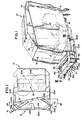
- the maintenance machine 10 may be of a general design as shown in Figure I. It should be understood however that the present invention is equally applicable to a riding unit as well as the walk-behind unit of Figure I.
- the surface maintenance or cleaning unit 10 includes a body 11 supported on the floor surface by a plurality of wheels 12 which allow movement of the machine or unit 10 across the floor surface.
- the machine or unit may have a steering mechanism 13 for control by the operator of the direction of travel of the unit 10.
- a power source 15 e.g., a propelling motor
- a tank 16 for containing scrubbing solution and mechanism 17 for applying the solution to the maintained surface may also be found within the body of the machine.
- the brushes are constructed and arranged on the unit so that in operation theywill rotate in the same rotational direction.
- This direction will be determined by the position of the leading brush 20a.
- the rotational direction of the trailing brush 20b will be with the forwardmost edge moving towards the leading brush and hence a clockwise rotation ( Figure II).
- the leading brush 20a would then rotate in a clockwise direction also.
- the C-shape configuration of the frame in the preferred embodiment includes a left-hand side extension 23a, a right-hand side extension 23b, and a forwardmost side 23c.
- the forwardmost side 23c is connected at either of its ends to a respective side extension 23a, 23b by obliquely arranged portions 23d shorter in length ( Figure II).
- Both of the left and right-hand side extensions 23a, 23b are designed to be of sufficient length such that when each is secured to the machine body 11, the extension will provide adequate support for the remainder of the frame and the hopper carried therein.
- one or more swivel casters 25a may be provided under the frame which will carry the majority of the frame weight in order to correct any balancing problems which might occur on downward grades.
- the correct height for any windrow flaps used in the invention may be set by the individual casters.
- the frame may be secured to the machine by any suitable mechanism such as welding, bolting, etc.
- the frame structure 21 does not cause any significant or noticeable change in the overall width of the maintenance machine 10.
- the dimensions and configuration of the frame will of course be determined by the size of the machine and the desired capacity of the debris hopper.
- a debris hopper 24 ( Figures I and IV) for containing the debris swept up by the disc brushes 20a, 20b is designed so that it is adjustable and fits snugly within the frame structure 21. If desired, the hopper may be securely mounted to the frame by bolts or screws, or other suitable mechanisms. It is important however that the hopper 24 be removably secured within the frame 21 so that the operator of the machine may conveniently dump the hopper of its contents whenever necessary.
- the back or rearward side of the hopper positioned close to the machine front end portion 18 is substantially open.
- a rearward opening 25 in the backside is defined by right and left-hand rear end portions 26, 27 respectively which extend inwardly towards each other.
- a generally elongated flexible member or ramp 32 (Figures III, IV and V).
- One end 33 of the flexible member 32 is positioned so as to be in contact with the debris conduit left-hand side 28b.
- the ramp 32 extends substantially along the full width of the hopper rearward opening 25 and is also secured to the hopper base 24a along the cutaway edge portion. This positioning places the member 32 directly in front of the greater portion of the pair of disc brushes 20a, 20b ( Figure III).
- the flexible ramp 32 is provided with spaced apart slit portions 34 which serve to facilitate the debris travelling beneath the ramp 32 for sweeping by the disc brushes 20a, 20b.
- other modifications in the flexible ramp member 32 are possible for allowing debris to pass therethrough.
- the ramp 32 is positioned close to the floor
- each blade 37, 38 is mounted in a manner which allows it to direct or push debris to a central area of the machine's path of movement. In this way, the blade acts as a windrow device for accomplishing full machine width sweeping without additional passings of the machine over the same surface area.
- each blade 37, 38 includes a flexible end portion 41, 42, respectively, which extends outwardly beyond the sides 23a, 23b, respectively, of the frame structure 21.
- the flexible end portions 41, 42 allow the machine to sweep close to walls and/or immovable objects while still achieving a full width sweep of the area.
- a pair of side rollers 43a and 43b serve to guide the scrubber along vertical surfaces, e.g. walls, to protect the machine and wall from damage.
- the debris hopper 24 may be provided with an access area or opening 45 which allows the operator a visual inspection of the interior of the hopper as well as observation of the operation of the disc brushes. The operator is thus able to determine if any blocking of the receiving mechanism is occurring and if the disc brushes are rotating properly.
- the opening may be large enough to allow the operator to manually insert objects into the hopper.
- the access opening may also serve to allow the operator to grasp the hopper and remove it from the frame structure for dumping.
- a preferred embodiment would be an opening 45 with downward flanges 47 to reduce the chances of debris bouncing out of the hopper. The flanges would also add strength to the opening for the purpose of lifting the hopper.
- a hinged door with a handle or a flexible slit flap are optional add-ons. The door may be transparent to permit visual observation of the contents.
- liquid drain openings may be provided in portions of the debris hopper to allow quantities of scrubbing solution which are swept up with the debris to be drained from the hopper. This may be deisrable for obvious reasons not the least of which would be to diminish the chances that the operator will spill accumulated solution on the clean floor surface when the hopper is being emptied. Additionally, a vacuum hose or other type of mechanism may be mounted in the debris hopper to remove the scrubbing solution.
- the left-hand brush could be selected as the leading brush, and then the direction of rotation for the pair of brushes would be counterclockwise.
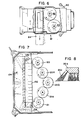
- a third embodiment of the invention is. itius-.. trated schematically in Figure VII.
- a plurality of disc brushes are used.
- the brushes are arranged in a V-formation with a forwardmost pair of brushes 120 and 121, spaced apart from each other but substantially side-by-side forming the opening of the V-shape.
- at least one more brush 120a and 121a respectively is secured slightly behind and to the inner side of the forwardmost brush located directly ahead.
- one additional brush 120b is shown, centered between and slightly rearwardly of brushes 120a and 121a.
- the brushes each rotate in a direction which will cause debris to be swept forwardly by the brushes towards the hopper mounted, as in the preferred embodiment, directly in front of the forwardmost brushes.
- the forwardmost brushes rotate in opposite directions, with the right hand brush rotating in a clockwise direction and the left-hand brush rotating in a counterclockwise direction.
- the brushes mounted directly behind each of the forwardmost brushes rotate in the same direction as the respective forwardmost brush ahead of it.
- the center brush 120b may be rotated in either direction.
- the hopper 124 in this third embodiment and the debris receiving mechanism 128 are substantially identical to that described in the foregoing discussion of the preferred embodiment, however, the debris receiving mechanism 128 has a ramp member 132 with a pair of end chutes 133 and 134.
- the blades 37, 38 catch the debris.
- the continued movement of the machine causes the debris to move inwardly along the respective blade to a central portion of the path being swept.
- the flexible ramp 32 then passes over the accumulated debris.
- the debris next contacts the rotating brushes 20a and/or 20b which typically rotate from approximately 160 rpm (revolutions per minute) up to 400 rpm or higher, with a common brush tip speed being 1340 fpm (feet per minute) (6.8 ms- 1 ).
- the present invention proves reliable for collecting and containing debris. It is constructed from low cost components and easily adjusted and readily removed from the machine. Fast, safe visual inspection and emptying of the hopper area is possible and convenience to the operator of the machine is greatly increased.
- the disc tool is a disc brush.
- the tool may be a scarifying tool or polishing pad.
Landscapes
- Architecture (AREA)
- Civil Engineering (AREA)
- Structural Engineering (AREA)
- Engineering & Computer Science (AREA)
- Electrical Discharge Machining, Electrochemical Machining, And Combined Machining (AREA)
- Cleaning Implements For Floors, Carpets, Furniture, Walls, And The Like (AREA)
- Cleaning In General (AREA)
- Vehicle Cleaning, Maintenance, Repair, Refitting, And Outriggers (AREA)
- Sampling And Sample Adjustment (AREA)
- Confectionery (AREA)
- Extrusion Moulding Of Plastics Or The Like (AREA)
- Pinball Game Machines (AREA)
- Indicating And Signalling Devices For Elevators (AREA)
- Slot Machines And Peripheral Devices (AREA)
- Nozzles For Electric Vacuum Cleaners (AREA)
- Finish Polishing, Edge Sharpening, And Grinding By Specific Grinding Devices (AREA)
Claims (14)
Priority Applications (1)
| Application Number | Priority Date | Filing Date | Title |
|---|---|---|---|
| AT83305285T ATE34911T1 (de) | 1982-09-10 | 1983-09-09 | Vorrichtung zum aufsammeln von schmutz. |
Applications Claiming Priority (2)
| Application Number | Priority Date | Filing Date | Title |
|---|---|---|---|
| US06/416,655 US4457036A (en) | 1982-09-10 | 1982-09-10 | Debris collecting mechanism |
| US416655 | 1982-09-10 |
Publications (3)
| Publication Number | Publication Date |
|---|---|
| EP0103471A2 EP0103471A2 (fr) | 1984-03-21 |
| EP0103471A3 EP0103471A3 (en) | 1985-11-13 |
| EP0103471B1 true EP0103471B1 (fr) | 1988-06-08 |
Family
ID=23650792
Family Applications (1)
| Application Number | Title | Priority Date | Filing Date |
|---|---|---|---|
| EP83305285A Expired EP0103471B1 (fr) | 1982-09-10 | 1983-09-09 | Dispositif pour ramasser des débris |
Country Status (7)
| Country | Link |
|---|---|
| US (1) | US4457036A (fr) |
| EP (1) | EP0103471B1 (fr) |
| JP (1) | JPS59118127A (fr) |
| AT (1) | ATE34911T1 (fr) |
| AU (1) | AU562101B2 (fr) |
| BR (1) | BR8304913A (fr) |
| DE (1) | DE3376955D1 (fr) |
Families Citing this family (33)
| Publication number | Priority date | Publication date | Assignee | Title |
|---|---|---|---|---|
| US4819676A (en) * | 1986-01-16 | 1989-04-11 | Tennant Company | Combination sweeping and scrubbing system and method |
| DE3708087A1 (de) * | 1987-03-13 | 1988-09-22 | Henkel Kgaa | Fahrbarer bodenreinigungsautomat |
| US5093955A (en) * | 1990-08-29 | 1992-03-10 | Tennant Company | Combined sweeper and scrubber |
| DE4118708C1 (fr) * | 1991-06-07 | 1992-08-20 | Zachhuber Kurt | |
| AU7854294A (en) * | 1993-10-04 | 1995-05-01 | Kurt Zachhuber | Multi-purpose floor-treatment machine |
| US5561921A (en) * | 1994-12-30 | 1996-10-08 | Zenon Airport Environmental, Inc. | Vehicular apparatus for removing snow and aircraft de-icing or anti-icing liquids from runway surfaces |
| US5485653A (en) * | 1994-04-25 | 1996-01-23 | Windsor Industries, Inc. | Floor cleaning apparatus |
| US6866705B2 (en) * | 2001-06-15 | 2005-03-15 | Larry Nielsen | Floor finishing and dust collection apparatus |
| US8051861B2 (en) | 2001-07-30 | 2011-11-08 | Tennant Company | Cleaning system utilizing purified water |
| US6671925B2 (en) * | 2001-07-30 | 2004-01-06 | Tennant Company | Chemical dispenser for a hard floor surface cleaner |
| US7051399B2 (en) | 2001-07-30 | 2006-05-30 | Tennant Company | Cleaner cartridge |
| US6748678B2 (en) * | 2002-06-12 | 2004-06-15 | Schmidt Engineering And Equipment, Inc. | Snow removal apparatus and method |
| US20120096671A1 (en) | 2010-10-26 | 2012-04-26 | Karcher North America, Inc. | Floor cleaning apparatus employing a combined sweeper and vaccum assembly |
| US7533435B2 (en) | 2003-05-14 | 2009-05-19 | Karcher North America, Inc. | Floor treatment apparatus |
| US8029739B2 (en) * | 2003-07-30 | 2011-10-04 | Tennant Company | Ultraviolet sanitation device |
| US8028365B2 (en) | 2003-09-02 | 2011-10-04 | Tennant Company | Hard and soft floor cleaning tool and machine |
| US20050081320A1 (en) * | 2003-10-20 | 2005-04-21 | Nichol Charles O. | Portable vacuum cleaner and method |
| US7100311B2 (en) * | 2004-05-07 | 2006-09-05 | Schmidt Engineering And Equipment, Inc. | Gate assembly and method for a snow plow blade |
| JP2008519657A (ja) | 2004-11-12 | 2008-06-12 | テナント・カンパニー | 可動フロアクリーナデータ通信 |
| MX2007013798A (es) * | 2005-05-05 | 2008-01-21 | Tennant Co | Maquina para barrido y fregado de pisos. |
| US8584294B2 (en) | 2005-10-21 | 2013-11-19 | Tennant Company | Floor cleaner scrub head having a movable disc scrub member |
| US20090089962A1 (en) * | 2007-09-25 | 2009-04-09 | Vanderlinden Roger P | Pick-up head with debris urging means for a mobile sweeper |
| US8365346B2 (en) * | 2008-12-15 | 2013-02-05 | Ecotech Service Co., Llc | Multi-purpose vacuum unit |
| US8966693B2 (en) | 2009-08-05 | 2015-03-03 | Karcher N. America, Inc. | Method and apparatus for extended use of cleaning fluid in a floor cleaning machine |
| USD654234S1 (en) | 2010-12-08 | 2012-02-14 | Karcher North America, Inc. | Vacuum bag |
| FR2997272A1 (fr) * | 2012-10-29 | 2014-05-02 | Actiwork | Balai pour vehicule automoteur |
| CN103989444B (zh) * | 2014-05-22 | 2016-05-25 | 晋江大森制衣有限公司 | 一种多功能地面清洁机 |
| KR102347395B1 (ko) * | 2017-04-14 | 2022-01-04 | 슈워츠 인더스트리즈, 인크. | 복수의 스위핑 모드를 갖는 도로 스위퍼 |
| WO2018202301A1 (fr) | 2017-05-04 | 2018-11-08 | Alfred Kärcher SE & Co. KG | Appareil de nettoyage des sols et procédé pour nettoyer la surface d'un sol |
| US11284702B2 (en) * | 2017-05-15 | 2022-03-29 | Sharkninja Operating Llc | Side brush with bristles at different lengths and/or angles for use in a robot cleaner and side brush deflectors |
| USD907868S1 (en) | 2019-01-24 | 2021-01-12 | Karcher North America, Inc. | Floor cleaner |
| CN116172464A (zh) * | 2021-11-26 | 2023-05-30 | 苏州诚河清洁设备有限公司 | 表面清洁设备 |
| GB2615080A (en) | 2022-01-26 | 2023-08-02 | Numatic Int Ltd | Floor treatment machine |
Family Cites Families (57)
| Publication number | Priority date | Publication date | Assignee | Title |
|---|---|---|---|---|
| US21868A (en) * | 1858-10-26 | Scbubbing-machine | ||
| US2712142A (en) * | 1955-07-05 | newcomer | ||
| US348778A (en) * | 1886-09-07 | Street-sweeper | ||
| US548201A (en) * | 1895-10-22 | hvass | ||
| US563869A (en) * | 1896-07-14 | Street-sweeper | ||
| US1510880A (en) * | 1924-10-07 | Sweeper | ||
| US670926A (en) * | 1899-06-09 | 1901-04-02 | Frederick C Austin | Street-sweeping machine. |
| US778427A (en) * | 1904-02-27 | 1904-12-27 | Henry John Noll | Scrubbing-machine. |
| US1687728A (en) * | 1923-11-19 | 1928-10-16 | Liddell Moses Volney | Gutter-broom attachment for sweeping machines |
| US1750829A (en) * | 1925-02-16 | 1930-03-18 | Austin Mfg Co | Gutter-broom street sweeper |
| US1773993A (en) * | 1927-11-11 | 1930-08-26 | Ernest J Newcomer | Floor-polishing machine |
| US1979797A (en) * | 1930-12-05 | 1934-11-06 | Walter S Finnell | Floor machine |
| US2142933A (en) * | 1937-04-03 | 1939-01-03 | George F Bickford | Waxing and polishing machine |
| US2248699A (en) * | 1937-04-06 | 1941-07-08 | Finnell System Inc | Floor scrubbing machine |
| US2236814A (en) * | 1938-05-12 | 1941-04-01 | Elgin Sweeper Co | Street sweeper and driving system therefor |
| US2199703A (en) * | 1938-10-05 | 1940-05-07 | Frank G Hough | Street sweeper |
| US2358119A (en) * | 1941-07-18 | 1944-09-12 | Joseph H Wilson | Floor waxing and polishing machine |
| US2680260A (en) * | 1947-08-06 | 1954-06-08 | Danielsson Nils Johan | Scrubbing machine with rotating brush for scrubbing surfaces |
| US2655678A (en) * | 1948-07-20 | 1953-10-20 | Keogh Hedley Benjamin | Mobile apparatus for working on roadways or the like |
| US2708280A (en) * | 1949-06-08 | 1955-05-17 | Austin Western Company | Street sweepers |
| US2589311A (en) * | 1949-09-26 | 1952-03-18 | Robert W Turner | Fluent material dispenser and spreader |
| US2683885A (en) * | 1949-10-21 | 1954-07-20 | Ewing M Johnson | Floor cleaning machine |
| US2657408A (en) * | 1949-12-17 | 1953-11-03 | Fred J Machovec | Power propelled sweeper |
| US2859461A (en) * | 1954-02-12 | 1958-11-11 | Clarke Sanding Machine Co | Sweeper drive and adjustment construction |
| FR1137016A (fr) * | 1955-11-21 | 1957-05-22 | Machine pour nettoyer les sols | |
| US2950494A (en) * | 1956-06-04 | 1960-08-30 | Edward J Dickson | Floor scrubbing machine |
| US2972159A (en) * | 1956-06-18 | 1961-02-21 | Tennant Co G H | Power sweeper |
| US2987741A (en) * | 1956-11-13 | 1961-06-13 | Marshall H Feldman | Machine for removing painted markings from pavement |
| GB830453A (en) * | 1957-03-05 | 1960-03-16 | Lewin Road Sweepers Ltd | Improvements in or relating to road sweeping machines |
| US3064292A (en) * | 1959-11-06 | 1962-11-20 | Fillery Gordon Thomas | Floor-maintenance machines |
| GB923960A (en) * | 1960-03-28 | 1963-04-18 | Asbrink & Co Ab | Improvements in or relating to mobile pneumatic cleaning devices |
| US3197798A (en) * | 1963-01-28 | 1965-08-03 | Tennant Co G H | Scrubbing machine |
| US3115654A (en) * | 1963-02-18 | 1963-12-31 | Zimmerman Lawrence | Barn sweeper |
| US3218657A (en) * | 1963-06-25 | 1965-11-23 | Sunbeam Corp | Foam generator for rug scrubbing apparatus |
| US3277511A (en) * | 1964-04-15 | 1966-10-11 | Nat Super Service Company | Adjustable width floor treating machine |
| US3401417A (en) * | 1966-09-15 | 1968-09-17 | Electrolux Corp | Rug washer attachment for floor polisher |
| US3458885A (en) * | 1966-12-19 | 1969-08-05 | Jan O Danielsson | Concrete aggregate exposing apparatus |
| US3490090A (en) * | 1967-07-13 | 1970-01-20 | Charles J Harrison | Mobile street cleaning apparatus |
| US3436788A (en) * | 1967-07-27 | 1969-04-08 | Wayne Manufacturing Co | Streetsweeper vacuum pickup head assembly |
| US3491395A (en) * | 1967-10-24 | 1970-01-27 | Scott & Fetzer Co | Power sweeper with main broom |
| NL6911257A (fr) * | 1969-07-22 | 1971-01-26 | ||
| US3639936A (en) * | 1970-06-08 | 1972-02-08 | Star Ind Inc | Self-propelled floor scrubber |
| US3701177A (en) * | 1971-04-22 | 1972-10-31 | Star Ind Inc | Front wheel driven floor scrubber |
| BE793182A (nl) * | 1971-12-27 | 1973-04-16 | Lely Nv C Van Der | Inrichting voor het opnemen van zich op de grond bevindend materiaal |
| US3866541A (en) * | 1972-03-24 | 1975-02-18 | Connor James M O | Self-propelled floor cleaning apparatus with movable brush |
| US3987512A (en) * | 1973-01-12 | 1976-10-26 | General Signal Corporation | Tilting floor cleaner |
| GB1473109A (fr) * | 1973-10-05 | 1977-05-11 | ||
| US3911518A (en) * | 1974-03-07 | 1975-10-14 | Raymond Lee Organization Inc | Floor cleaning device |
| US4006506A (en) * | 1975-02-10 | 1977-02-08 | The Scott & Fetzer Company | Surface cleaning machine with squeegee assembly |
| US3996636A (en) * | 1975-12-17 | 1976-12-14 | Star Industries, Inc. | Floor scrubbing machine |
| US4009500A (en) * | 1976-04-26 | 1977-03-01 | Star Industries, Inc. | Floor scrubbing apparatus |
| US4084281A (en) * | 1976-07-16 | 1978-04-18 | Eugene David Smith | Fluid-powered rotary brush |
| US4141567A (en) * | 1977-01-31 | 1979-02-27 | Scott Gary M | Handle bar hand guards |
| US4183112A (en) * | 1977-08-02 | 1980-01-15 | Milliken Research Corporation | Device for scrubbing carpet |
| US4200953A (en) * | 1978-10-05 | 1980-05-06 | Fmc Corporation | Surface sweeper with floating broom chamber |
| US4218798A (en) * | 1979-06-19 | 1980-08-26 | Clarke-Gravely Corporation | Floor treating machine |
| US4369540A (en) * | 1981-03-27 | 1983-01-25 | The Scott & Fetzer Company | Floor cleaning machine |
-
1982
- 1982-09-10 US US06/416,655 patent/US4457036A/en not_active Expired - Fee Related
-
1983
- 1983-09-06 AU AU18757/83A patent/AU562101B2/en not_active Ceased
- 1983-09-09 JP JP58165320A patent/JPS59118127A/ja active Pending
- 1983-09-09 BR BR8304913A patent/BR8304913A/pt unknown
- 1983-09-09 AT AT83305285T patent/ATE34911T1/de not_active IP Right Cessation
- 1983-09-09 EP EP83305285A patent/EP0103471B1/fr not_active Expired
- 1983-09-09 DE DE8383305285T patent/DE3376955D1/de not_active Expired
Also Published As
| Publication number | Publication date |
|---|---|
| BR8304913A (pt) | 1984-04-24 |
| US4457036A (en) | 1984-07-03 |
| AU1875783A (en) | 1984-03-15 |
| AU562101B2 (en) | 1987-05-28 |
| ATE34911T1 (de) | 1988-06-15 |
| EP0103471A3 (en) | 1985-11-13 |
| EP0103471A2 (fr) | 1984-03-21 |
| JPS59118127A (ja) | 1984-07-07 |
| DE3376955D1 (en) | 1988-07-14 |
Similar Documents
| Publication | Publication Date | Title |
|---|---|---|
| EP0103471B1 (fr) | Dispositif pour ramasser des débris | |
| US3197798A (en) | Scrubbing machine | |
| US5093955A (en) | Combined sweeper and scrubber | |
| US4624026A (en) | Surface maintenance machine with rotary lip | |
| US6108859A (en) | High efficiency squeegee | |
| AU2006244470B2 (en) | Floor sweeping and scrubbing machine | |
| US5623743A (en) | Mobile surface scrubber solution recovery system | |
| US4580313A (en) | Walk behind floor maintenance machine | |
| US7281296B2 (en) | Debris collection systems, vehicles, and methods | |
| JP4226871B2 (ja) | スクラブ機受動再循環 | |
| US7958595B2 (en) | Floor cleaning apparatus | |
| US6192542B1 (en) | Sweeper conveyor overflow and leakage recycling ramp | |
| US4561145A (en) | Continuous sweep for road planing and milling machines | |
| US3591883A (en) | Two-stage lawn sweeper | |
| JPH04506846A (ja) | 自走式海浜清掃作業車 | |
| US6990709B2 (en) | Vacuum sweeping system for automatic scrubber | |
| EP0476483B1 (fr) | Unité universelle de balayage | |
| US5596784A (en) | Vehicle for collecting debris from a road | |
| US1694937A (en) | Floor-scrubbing machine | |
| EP0039558A2 (fr) | Balai mécanique | |
| JP3556499B2 (ja) | 乗用型芝生面清掃機 | |
| US5244333A (en) | Pickup sweeper for roofing gravel | |
| CA1218203A (fr) | Mecanisme capteur de debris | |
| US3101498A (en) | Sweeper | |
| GB2137486A (en) | Floor sweeper |
Legal Events
| Date | Code | Title | Description |
|---|---|---|---|
| PUAI | Public reference made under article 153(3) epc to a published international application that has entered the european phase |
Free format text: ORIGINAL CODE: 0009012 |
|
| AK | Designated contracting states |
Designated state(s): AT BE CH DE FR GB IT LI LU NL SE |
|
| PUAL | Search report despatched |
Free format text: ORIGINAL CODE: 0009013 |
|
| AK | Designated contracting states |
Designated state(s): AT BE CH DE FR GB IT LI LU NL SE |
|
| 17P | Request for examination filed |
Effective date: 19860206 |
|
| 17Q | First examination report despatched |
Effective date: 19870206 |
|
| GRAA | (expected) grant |
Free format text: ORIGINAL CODE: 0009210 |
|
| AK | Designated contracting states |
Kind code of ref document: B1 Designated state(s): AT BE CH DE FR GB IT LI LU NL SE |
|
| PG25 | Lapsed in a contracting state [announced via postgrant information from national office to epo] |
Ref country code: NL Effective date: 19880608 Ref country code: IT Free format text: LAPSE BECAUSE OF FAILURE TO SUBMIT A TRANSLATION OF THE DESCRIPTION OR TO PAY THE FEE WITHIN THE PRESCRIBED TIME-LIMIT;WARNING: LAPSES OF ITALIAN PATENTS WITH EFFECTIVE DATE BEFORE 2007 MAY HAVE OCCURRED AT ANY TIME BEFORE 2007. THE CORRECT EFFECTIVE DATE MAY BE DIFFERENT FROM THE ONE RECORDED. Effective date: 19880608 Ref country code: FR Free format text: THE PATENT HAS BEEN ANNULLED BY A DECISION OF A NATIONAL AUTHORITY Effective date: 19880608 Ref country code: BE Effective date: 19880608 Ref country code: AT Effective date: 19880608 |
|
| REF | Corresponds to: |
Ref document number: 34911 Country of ref document: AT Date of ref document: 19880615 Kind code of ref document: T |
|
| REF | Corresponds to: |
Ref document number: 3376955 Country of ref document: DE Date of ref document: 19880714 |
|
| PG25 | Lapsed in a contracting state [announced via postgrant information from national office to epo] |
Ref country code: GB Effective date: 19880909 |
|
| PG25 | Lapsed in a contracting state [announced via postgrant information from national office to epo] |
Ref country code: SE Effective date: 19880910 |
|
| PG25 | Lapsed in a contracting state [announced via postgrant information from national office to epo] |
Ref country code: LU Free format text: LAPSE BECAUSE OF NON-PAYMENT OF DUE FEES Effective date: 19880930 Ref country code: LI Effective date: 19880930 Ref country code: CH Effective date: 19880930 |
|
| EN | Fr: translation not filed | ||
| NLV1 | Nl: lapsed or annulled due to failure to fulfill the requirements of art. 29p and 29m of the patents act | ||
| PLBE | No opposition filed within time limit |
Free format text: ORIGINAL CODE: 0009261 |
|
| STAA | Information on the status of an ep patent application or granted ep patent |
Free format text: STATUS: NO OPPOSITION FILED WITHIN TIME LIMIT |
|
| 26N | No opposition filed | ||
| REG | Reference to a national code |
Ref country code: CH Ref legal event code: PL |
|
| GBPC | Gb: european patent ceased through non-payment of renewal fee | ||
| PG25 | Lapsed in a contracting state [announced via postgrant information from national office to epo] |
Ref country code: DE Effective date: 19890601 |
|
| EUG | Se: european patent has lapsed |
Ref document number: 83305285.5 Effective date: 19890712 |