EP0100539A2 - Zusammengefügte Anordnung zur Halterung von Halbleiterscheiben oder ähnlichem - Google Patents
Zusammengefügte Anordnung zur Halterung von Halbleiterscheiben oder ähnlichem Download PDFInfo
- Publication number
- EP0100539A2 EP0100539A2 EP83107498A EP83107498A EP0100539A2 EP 0100539 A2 EP0100539 A2 EP 0100539A2 EP 83107498 A EP83107498 A EP 83107498A EP 83107498 A EP83107498 A EP 83107498A EP 0100539 A2 EP0100539 A2 EP 0100539A2
- Authority
- EP
- European Patent Office
- Prior art keywords
- rods
- supporting
- assembled device
- notch
- notches
- Prior art date
- Legal status (The legal status is an assumption and is not a legal conclusion. Google has not performed a legal analysis and makes no representation as to the accuracy of the status listed.)
- Withdrawn
Links
Images


Classifications
-
- C—CHEMISTRY; METALLURGY
- C30—CRYSTAL GROWTH
- C30B—SINGLE-CRYSTAL GROWTH; UNIDIRECTIONAL SOLIDIFICATION OF EUTECTIC MATERIAL OR UNIDIRECTIONAL DEMIXING OF EUTECTOID MATERIAL; REFINING BY ZONE-MELTING OF MATERIAL; PRODUCTION OF A HOMOGENEOUS POLYCRYSTALLINE MATERIAL WITH DEFINED STRUCTURE; SINGLE CRYSTALS OR HOMOGENEOUS POLYCRYSTALLINE MATERIAL WITH DEFINED STRUCTURE; AFTER-TREATMENT OF SINGLE CRYSTALS OR A HOMOGENEOUS POLYCRYSTALLINE MATERIAL WITH DEFINED STRUCTURE; APPARATUS THEREFOR
- C30B31/00—Diffusion or doping processes for single crystals or homogeneous polycrystalline material with defined structure; Apparatus therefor
- C30B31/06—Diffusion or doping processes for single crystals or homogeneous polycrystalline material with defined structure; Apparatus therefor by contacting with diffusion material in the gaseous state
- C30B31/10—Reaction chambers; Selection of materials therefor
- C30B31/103—Mechanisms for moving either the charge or heater
-
- H—ELECTRICITY
- H10—SEMICONDUCTOR DEVICES; ELECTRIC SOLID-STATE DEVICES NOT OTHERWISE PROVIDED FOR
- H10P—GENERIC PROCESSES OR APPARATUS FOR THE MANUFACTURE OR TREATMENT OF DEVICES COVERED BY CLASS H10
- H10P95/00—Generic processes or apparatus for manufacture or treatments not covered by the other groups of this subclass
-
- C—CHEMISTRY; METALLURGY
- C30—CRYSTAL GROWTH
- C30B—SINGLE-CRYSTAL GROWTH; UNIDIRECTIONAL SOLIDIFICATION OF EUTECTIC MATERIAL OR UNIDIRECTIONAL DEMIXING OF EUTECTOID MATERIAL; REFINING BY ZONE-MELTING OF MATERIAL; PRODUCTION OF A HOMOGENEOUS POLYCRYSTALLINE MATERIAL WITH DEFINED STRUCTURE; SINGLE CRYSTALS OR HOMOGENEOUS POLYCRYSTALLINE MATERIAL WITH DEFINED STRUCTURE; AFTER-TREATMENT OF SINGLE CRYSTALS OR A HOMOGENEOUS POLYCRYSTALLINE MATERIAL WITH DEFINED STRUCTURE; APPARATUS THEREFOR
- C30B31/00—Diffusion or doping processes for single crystals or homogeneous polycrystalline material with defined structure; Apparatus therefor
- C30B31/06—Diffusion or doping processes for single crystals or homogeneous polycrystalline material with defined structure; Apparatus therefor by contacting with diffusion material in the gaseous state
- C30B31/14—Substrate holders or susceptors
Definitions
- This invention relates to a device for supporting semiconductor wafers or the like, and a mother boat for this device.
- the aforesaid supporting device and mother boat should, for example, (a) be made of .a material which is substantially the same as the semiconductor wafers or does not substantially react with the semiconductor wafers so as to avoid adverse effects such as adhesion and diffusion of foreign matter to and in the semiconductor wafers subjected to diffusion treatment, and (b) have resistance to high temperatures in the diffusion furnace.
- the supporting device and the mother boat are generally formed of silicon or quartz glass. Since silicon is hard and brittle, it is extremely difficult, if not impossible, to suject it to complex machining, and parts made of silicon cannot be melt-adhered to each other. In the case of silicon, therefore, it was the previous practice to subject a silicon block to relatively simple machining such as cutting and grooving and thus produce a supporting device or mother boat composed of such a single block. On the other hand, since quartz glass can be melt-adhered, a supporting device or mother boat of quartz glass is produced in the prior art generally by melt-adhering a plurality of parts made of it into a unitary structure.
- supporting devices or mother boats made of silicon or quartz glass have the following problems to be solved. Firstly, since supporting devices or mother boats of silicon are composed of a single silicon block subjected to relatively simple machining, they naturally require a relatively large amount of the considerably expensive material, and the cost of production becomes high. Secondly, such a supporting device or mother boat is exposed to - considerable temperature variations as a result of putting it into and out of a diffusion furnace, and undergoes local damage by thermal stresses. Local damage, however, makes the entire supporting device or mother boat useless because it is of a one-piece structure or made by melt-adhesion of parts.
- Another object of this invention is to provide an assembled supporting device and an assembled mother boat, which can be produced relatively easily with a minimum of material required and hence a considerably reduced cost of production.
- Still another object of this invention is to provide an assembled supporting device and an assembled mother boat, which, in the event of local damage, can be repaired for further use only by exchanging that part which has undergone damage.
- Yet another object of this invention is to provide an assembled supporting device and an assembled mother boat, which can be easily assembled and disassembled.
- a further object of this invention is to provide an assembled supporting device and an assembled mother boat, which have increased heat resistance and strength.
- An additional object of this invention is to provide an assembled supporting device for supporting a plurality of semiconductor wafers or the like to be treated in a vertical furnace, which can support the semiconductor wafers in the furnace in such a state that their free end portions extend inclinedly upwardly, but which, when the semiconductor wafers are loaded into the device or withdrawn from it, can handle them in a substantially upstanding state, and therefore can permit easy automation of the loading and withdrawal of the semiconductor wafers into and from the device.
- an assembled device for supporting semiconductor wafers or the like comprising two end supports spaced from each other horizontally with a predetermined distance therebetween and at least two rods extending across said end supports with one end portion of each rod being detachably combined with one of said end supports and the other end portion thereof being detachably combined with the other end support, at least one of said rods having formed therein a plurality of holding grooves spaced longitudinally thereof.
- an assembled mother boat on which to place devices for supporting semiconductor wafers or the like said_boat comprising a pair of side plates spaced laterally from each other, a pair of end plates spaced from each other in the front and rear directions, and a pair of wheeel members spaced from each other in the front and rear directions, said pair of side plates being detachably combined with said pair of end plates so that their relative movements in the front and rear directions and the lateral direction can be prevented, and said pair of wheel members being located between, and rotatably combined with, said pair of side plates.
- an assembled device for supporting semiconductor wafers or the like comprising at least one end support, and at least two rods each extending substantially vertically from one end portion thereof combined detachably with said end support, each of said rods having formed therein a plurality of holding grooves spaced from each other longitudinally thereof.
- an assembled device for supporting semiconductor wafers or the like comprising two end supports spaced from each other and at least two rods each extending across said end supports with one end portion thereof being combined detachably with one of said end supports and the other end portion being detachably combined with the other end support, each of said rods having formed therein a plurality of holding grooves spaced longitudinally thereof, and said end supports being spaced from each other vertically so that said rods extend substantially vertically.
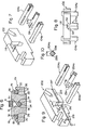
- Figure 1 shows by an exploded view one specific embodiment of the assembled device of this invention for supporting semiconductor wafers or the like to be applied to a substantially horizontally extending lateral furnace.
- the device shown is comprised of two end supports 2a and 2b, three rods 4a, 4b and 4c, and one additional part 6.
- Each of the end supports 2a and 2b may be of any suitable shape. Conveniently, it is of a wide nearly rectangular shape with a low center of gravity so as to be able to stand by itself stably.
- the lower end of each of the end supports 2a and 2b has formed therein a base portion 8 projecting slightly downwardly and having a substantially horizontally extending flat under surface.
- the upper edge of each of the end supports 2a and 2b includes a central portion 10 defined by a substantially horizontally extending flat surface and two side portions 12 and 14 defined by inclined flat surfaces inclined downwardly at a predetermined angle and extending outwardly in the widthwise direction.
- Each of the end supports 2a and 2b has formed therein three supporting notches, i.e.
- the central supporting notch 16 extends from the center of the central portion 10 downwardly and substantially vertically to a relatively deep site. Both side surfaces of the central supporting notch 16 extend substantially parallel to each other with a predetermined distance therebetween.
- the bottom of the central supporting notch 16 is defined by two inclined planes 22 and 24 which extend inclinedly upwardly toward both sides at an angle of about 45 degrees and reach the aforesaid both side surfaces.
- the side supporting notches 18 and 20 extend relatively shallow, while they are inclined downwardly toward the center of each of the end supports from the two side portions 12 and 14 defined by inclined surfaces, preferably substantially perpendicular to the two side portions 12 and 14.
- each of the side supporting notches 18 and 20 extend substantially parallel to each other with a predetermined distance therebetween.
- the bottoms of the side supporting notches 18 and 20 are defined respectively by two planes, i.e. substantially vertical planes 26 and 28 and substantially horizontal planes 30 and 32.
- Each of the three rods 4a, 4b and 4c may have a suitable cross-sectional shape such as a circle or polygon. Preferably, it has a rectangular, particularly square, cross-sectional shape for the ease of production, and the ease of handling during assembling and disassembling.
- An engaging notch for engagement with each of the end supports 2a and 2b is formed at each of the opposite end portions of the three rods 4a, 4b and 4c.
- Figure 2 which is a sectional view taken along line II-II of Figure 1 together with Figure 1, each of the end portions of the centrally located rod 4a has formed therein two engaging notches 34 by cutting its two diagonally opposing corner portions, i.e.
- each of such engaging notches 34 is substantially equal to, or slightly larger than, the thickness ta or tb ( Figure 1) of the end supports 2a or 2b.
- the residual thickness rl ( Figure 2) between the two engaging notches 34 is substantially equal to, or slightly smaller, than the width wl ( Figure 1) of the central supporting notch 16 formed in each of the end supports 2a and 2b.
- FIG. 3 which is a sectional view taken along line III-III of Figure 1 together with Figure 1, in each of the side portions of each of the two rods 4b and 4c located on both sides of the rod 4a, two diagonally opposing corner portions, i.e. a corner portion located at the inward top end and a corner located at the outward bottom end in Figures 1 and 3, are cut to provide substantially perpendicular planes, and thus form two engaging notches 36.
- the longitudinal size k 2 ( Figure 1) of each of such engaging notches 36 is substantially equal to, or slightly larger than, the thickness ta or tb ( Figure 1) of the end support 2a or 2b.
- the residual thickness r2 ( Figure 3) between the two notches 36 is substantially equal to, or slighty smaller than, the width w2 ( Figure 1) of each of the side supporting notches 18 and 20 formed in the end supports 2a and 2b.
- a plurality of holding grooves are formed at predetermined intervals in the longitudinal direction.
- a plurality of holding grooves 38 longitudinally spaced from each other are formed at that corner portion of the rod 4a which is located uppermost.
- a plurality of holding grooves 40 arranged longitudinally at predetermined intervals are formed on that corner portion which is located at the inward top end of each rod.
- each of the holding grooves 38 and 40 is tapered so that its width gradually decreases to a predetermined depth s from its open end. From the predetermined depth to the bottom, each groove preferably has substantially the same width w3.
- the width w3 is substantially equal to, or slightly larger than, the thickness of a wafer or the like to be inserted in the grooves 38 and 40.
- a supporting notch 42 for combining the additional part 6 is formed at the end support 2a by enlarging the width of the upper end portion of the central supporting notch 16.
- the additional part-6 has a main portion 46 having a vertically extending opening 44 formed therein, and an engaging portion projecting forwardly from the main portion 46.
- a rectangular engaging notch 50 is formed in the lower surface of the engaging portion 48.
- the longitudinal sizej(- of the engaging notch 50 is substantially equal to, or slightly larger than, the thickness ta of the end support 2a.
- the width w4 in the lateral direction of the engaging portion 48 is substantially equal to, or slightly smaller than, the width w5 of the enlarged supporting notch 42.
- the two end supports 2a and 2b, the three rods 4a, 4b and 4c and the additional part 6 are assembled as shown in Figure 5 to form a device for supporting semiconductor wafers 52 or the like.
- Figure 6 which is a sectional view taken along line IV-IV of Figure 5 together with Figures 1 and 5, the two end supports 2a and 2b are set with a predetermined distance therebetween in the front and rear directions.
- the centrally located rod 4a is combined with the end supports 2a and 2b by aligning the two engaging notches 34 formed at the opposite ends of the rod 4a with the central supporting notches 16 formed in the end supports 2a and 2b, and inserting them into the central supporting notches 16 from above.
- the bottom surfaces of the two engaging notches 34 are positioned adjacent to, or in contact with, the two side surfaces of the central supporting notches 16, and the two adjoining non-notched surfaces of the lower portion of the rod 4a are brought into contact with the two inclined planes 22 and 24 defining the bottom of the central supporting notch 16.
- the rod 4a is supported with sufficient stability in the state shown in Figures 5 and 6 in which that corner portion in which the holding grooves 38 are formed is positioned uppermost.
- the non-notched portions at both ends of the rod 4a are located exteriorly of the front and rear directions of the end supports 2a and 2b, the rod 4a is prevented from moving in the front and rear directions with respect to the end supports 2a and 2b.
- the rod 4b on one side is combined with the end supports 2a and 2b by aligning the two engaging notches 36 formed at the opposite end portions of the rod 4b with the side supporting notches 18 formed in the supports 2a and 2b, and inserting them into the side supporting notches 18. Consequently, as can be easily understood from Figure 6, the bottom surfaces of the two notches 36 are positioned adjacent to, or in contace with, the two side surfaces of the side supporting notches 18, and the two adjoining non-notched surfaces of the rod 4b at its inside and under side are brought into contact with the substantially vertical plane 26 and the substantially horizontal plane 30 defining the bottom of each side supporting notch 18.
- the rod 4b is supported with sufficient stability in the state shown in Figures 5 and 6 in which that corner portion in which the holding grooves 40 are formed is located at the inward top end of the rod 4b. Furthermore, since the non-notched portions at both ends of the rod 4b are located exteriorly of the front and rear directions of the end supports 2a and 2b, the rod 4b is prevented from moving in the front and rear directions with respect to the end supports 2a and 2b. Likewise, the rod 4c located on the other side is combined with the end supports 2a and 2b by aligning the two engaging notches 36 formed at the opposite end portions of the rod 4b with the side supporting notches 20 formed in the end supports 2a and 2b, and inserting them into the side supporting notches 20.
- the bottom surfaces of the two notches 36 are positioned adjacent to, or in contact with, the two side surfaces of the side supporting notches 20, and the two adjoining non-notched surfaces of the rod 4c at its inside and underside are brought into contact with the substantially vertical plane 28 and the substantially horizontal plane 32 defining the bottom of each side supporting notch 20. Consequently, the rod 4c is supported with sufficient stability in the state shown in Figures 5 and 6 in which that corner portion in which the holding grooves are formed is positioned at the inward top end of the rod 4c.
- the rod 4c Since the non-notched portions at both ends of the rod 4c are positioned exteriorly of the front and rear directions of the end supports 2a and 2b, the rod 4c is prevented from moving in the front and rear directions with respect to the end supports 2a and 2b.
- the three rods 4a, 4b and 4c extend substantially horizontally and in parallel with each other across the two end supports 2a and 2b.
- the three rods 4a, 4b and 4c are located at substantially equal intervals, and thus the distance between the rods 4a and 4b is substantially equal to the distance between the rods 4a and 4c.
- the two rods 4b and 4c on both sides are located on the same level.
- the centrally located rod 4a is on a lower level than the two rods 4b and 4c.
- the additional part 6 is combined with the end support 2a by bringing the engaging notch 50 formed on the under surface of its engaging portion 48 into engagement with the supporting notch 42 of the end support 2a. It will be easily understood that when the engaging notch 50 is engaged with the supporting notch 42, the additional part 6 is prevented from moving in the front and rear directions and the lateral direction with respect to the end support 2a, and thus maintained stable on the end support 2a.
- the various component parts constituting the assembled device which can be freely disassembled are made of silicon.
- these various parts may be formed of quartz glass instead of silicon.
- the rods 4a, 4b and 4c may, if desired, be reinforced with a suitable reinforcing material such as a metallic materail or heat-resistant fibers extending longitudinally in the quartz glass in order to increase their strength.
- the peripheral portion of one wafer 52 is inserted in a set of three holding grooves (i.e., one holding groove 38 and two holding grooves 40), which are aligned laterally, in the holding grooves 38 and 40 formed on the rods 4a, 4b and 4c.
- a plurality of wafers 52 are supported in juxtaposition at predetermined intervals in the front and rear directions of the rods 4a, 4b and 4c.
- Each wafer 52 nearly disc-like in shape is inserted in the aforesaid set of holding grooves 38 and 40 at three circumferentially spaced positions in its lower peripheral portion, and therefore, is supported accurately in the required state.
- the assembled device supporting the plurality of wafers 52 is pushed forwardly and put into a lateral diffusion furnace (not shown) extending substantially horizontally.
- the additional part 6 combined with the end support 2a can be utilized when the assembled device supporting the wafers is withdrawn from the diffusion furnace after the diffusion treatment.
- the assembled device can be withdrawn from the diffusion furnace by hooking the opening 44 of the additional part 6 with a hook-like portion formed at the tip of a withdrawing instrument (not shown) known per se, and pulling the device.
- the additional part 6 may be omitted, and the assembled device may be withdrawn from the diffusion furnace by hooking a suitable site of the end support 2a, etc.
- the assembled device To clean, transport or otherwise handling the assembled device, it may, if desired, be disassembled into its component parts.
- the disassembling operation can be very easily carried out by performing the aforesaid assembling operation reversely.
- the assembled device constructed in accordance with this invention Since the various parts constituting the assembled device have relatively simple shapes, they can be produced relatively easily at low cost. When compared with the case of producing the entire device as a one-piece structure from a single block, the amount of the considerably expensive material can be drastically decreased, and therefore, the cost of production can be greatly.reduced.
- the various components can be assembled and disassembled very easily. When the device has undergone local damage by exposure to great heat variation, etc., it is sufficient to exchange only that part which has been damaged, and the device can be further used. This offers an economical advantage.
- the assembled device constructed in accordance with this invention undergoes a much lesser degree of damage than a device constructed as a one-piece structure when exposed to great heat variations. No clear reason has yet been assigned to this fact. It is theorized however that in the device constructed as a one-piece structure, thermal expansions or thermal shrinkages of various portions interact to exert a considerably great stress on these portions, but in the assembled device constructed in accordance with this invention, the thermal expansions or thermal shrinkages of the various component parts are effectively compensated for by the so-called "plays" necessarily formed at joining parts of the various components parts owing to production tolerances.
- the device constructed in accordance with this invention also brings about the following advantage.
- the relative positions of the rods particularly the lateral distances between the rods, should be made to correspond to the diameters of the wafers or the like, as can be easily understood from Figure 5.
- the relative positions of the rods in the assembled device can be properly changed by using another pair of end supports having a central supporting notch and side supporting notches at different relative positions.
- the three rods 4a, 4b and 4c extending across the two end supports 2a and 2b are used. If desired, the centrally located rod 4a may be omitted, or four or more rods extending across the two end supports 2a and 2b may be used.
- the holding grooves 38 and 40 are formed in all of the three rods 4a, 4b and 4c. It is also possible, for example, to form holding grooves 38 only in the centrally located rod 4a, and to make the two rods 4b and 4c located on both sides highly resistant to friction by, for example, knurling their surfaces finely instead of forming holding grooves 40 so that the edges of the wafers or the like are held by the rods 4b and 4c without slippage.
- the holding grooves 38 and 40 are formed on the corner portions of the rods 4a, 4b and 4c having a square cross-sectional shape.
- the holding grooves may be formed on the flat surface portions of the rods 4a, 4b and 4c. In this regard, however, the following fact should be noted.
- the amount of the material to be cut off from the rods 4a, 4b and 4c in order to form holding grooves of a predetermined depth can be much smaller than in the case of forming such grooves on the flat surface-portions of the rods 4a, 4b and 4c.
- grooves can be formed on the corner portions of the rods 4a, 4b and 4c more easily and rapidly than on thire flat surface portions, and the reduction of the strength of the rods 4a, 4b and 4c owing to the formation the holding grooves can be lessened as compared with the case of forming the grooves on their flat surfaces.
- the end portions of the rods 4a, 4b and 4c are combined with the end supports 2a and 2b by forming the supporting notches 16, 18 and 20 in the end supports 2a and 2b and the engaging notches 34 and 36 in the end portions of the rods 4a, 4b and 4c.
- combining of the end portions of the rods 4a, 4b and 4c with the end supports 2a and 2b in a detachable manner can be effected by various other methods.
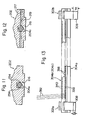
- Figure 7 shows a modified example of the manner of combining an end support 102 with a centrally located rod 104a.
- a central supporting notch 116 formed in the end support 102 is formed not entirely over the thickness of the end support 102, but only on the inward side of the end support 102.
- the centrally located rod 104a is somewhat shorter thar two rods 104b and 104c positioned on both sides of the rod 104a.
- Two engaging notches 134 are formed at the end portion of the rod 104a without leaving non-notchec portions at its end (see Figure 8 also).
- each of the engaging notches 134 is substantially equal to, or slightly larger than, the size w6 of the supporting notch 116 in the front and rear directions.
- the end portion of the centrally located rod 104a is combined with the end support 102 by aligning the two engaging notches 134 formed therein with the central supporting notch l16 and inserting them into the central supporting notch 116 from above, as shown in Figure 8.
- the other end portion (not shown) of the centrally located rod 104a is combined with another end support (not shown) by the same method as above.
- the manner of combining the end portions of the two rods 104b and 104c located on both sides of the rod 104a with the end support 102 and other constructions may be the same as in the above embodiment shown in Figures 1 to 6.
- the end portion of the centrally located rod 104a can also be combined with the end support 102 with sufficient stability.
- the central supporting notch 116 formed in the end support 102 does not extend over the entire thickness of the end support 102 but exists only in its inner side.
- the reduction of the strength of the end support 102 owing to the formation of the central supporting notch 116 is'considerably lessened.
- the end support 102 shown in Figures 7 and 8 has higher strength than the end supports 2a and 2b shown in Figures 1, 5 and 6.
- Figure 9 shows another modified example of the manner of combining an end support 202 with a centrally located rod 204a.
- a central supporting notch 216 formed in the end support 202 extends upwardly substantially vertically to a predetermined height from the central portion of the lower edge of the end support 202 instead of extending downwardly from the central portion of the upper edge of the end support 202.
- the central supporting notch 216 is formed not over the entire thickness of the end support 202 by only in the inner side surface of the end support 202, as in the modified example shown in Figures 7 and 8.
- the centrally located rod 204a is slightly shorter than two rods 204b and 204c located on both sides of the rod 204a, and two engaging notches 234 are formed at the end portion of the centrally located rod 204a without leaving non-notched portions at its end.
- Figure 10 which is a sectional view taken along line X-X of Figure 9, the two engaging notches 234 are formed in those corner portions of the rod 204a which are positioned at its lateral sides.
- the longitudinal sizep' of each of the engaging notches 234 is slightly smaller than the depth d' of the central supporting notch 216.
- a channel 217 is formed which extends in the inside surface of the end support 202 laterally and substantially horizontally and crosses the central supporting notch 216.
- An upwardly facing bottom surface 219 of the channel 217 defines a shoulder portion for supporting the end portion of the centrally located rod 204a as will be seen from the following description.
- the depth d" of the channel 217 is slightly smaller than the depth d' of the central supporting notch 216.
- the end portion of the centrally located rod 204a is combined with the end support 202 in the following manner.
- the end of the rod 204a is positioned as required with respect to the inside surface of the end support 202.
- the rod 204a is advanced longitudinally relative to the end support 202 and inserted in the central supporing notch 216.
- the residual thickness r2 ( Figure 10) between the two engaging notches 234 is substantially equal to, or slightly smaller than, the width w7 of the central supporting notch 216
- the notched end portion of the rod 204a having the two engaging notches 234 formed therein advances to a deep site of the central supporting notch 216 beyond the channel 217 as shown in Figure 11.
- the corner portions on both lateral sides are located laterally outwardly of the central supporting notch 216.
- the corner portions existing on both lateral sides of the non-notched portion are received in the channel 217 as shown in Figure 12, the non-notched portion is also caused to advance to the inlet side of the central supporting notch 216.
- the corner portions .existing on both lateral sides of the non-notched portion are positioned on a shoulder portion defined by the bottom surface 219 of the channel 217.
- the other end portion (not shown) of the centrally located rod 204a is combined with another end support (not shown) in the same manner as above.
- the manner of combining the end portions of the two rods 204b and 204c located on both sides of the rod 204a with the end support 102 and other constructions may be the same as in the embodiment shown in Figures 1 to 6.
- the centrally located rod 204a should generally be positioned on a lower level than the two rods 204b and 204c located on both sides thereof. Accordingly, when a central supporting notch is to be formed so as to extend downwardly from the upper edge of the end support 202 substantially vertically, the central supporting notch should extend to a considerable depth from the upper edge of the end support 202. Thus, a considerable amount of the material should be cut off from the end support 202 in order to form the central supporting notch.
- the central supporting notch 216 may be formed so as to extend upwardly from the lower edge of the end support 202 instead of forming it so as to extend downwardly from the upper edge of the end support 202.
- the amount of material cut off from the end support 202 for the formation of the central supporting notch .216 can be decreased, and the reduction of the strength of the end support 202 owing to the formation of the central supporting notch 216 can be lessened.
- rods 4a, 4b and 4c extend substantially horizontally across the two end supports 2a and 2b.
- rods 304a 304b and 304c may be caused to extend upwardly inclinedly at some angle (for example an angle of about 5 to 10 degrees) from an end support 302a toward an end support 302b.
- the width w3 ( Figure 4) of each of the holding grooves 38 and 40 formed in the rods 4a, 4b and 4c is generally set at a value slightly larger than the thickness of a wafer to be inserted therein. Even when the width w3 of each of the holding grooves 38 and 40 is made substantially equal to the thickness of the wafer, the width w3 of each of the holding grooves 38 and 40 will become slightly larger if the contaminated rods 4a, 4b and 4c are washed with a washing solution such as hydrofluoric acid.
- non-uniformity occurs in the distance between the wafers.
- This non-uniformity increases as the inclination of the wafers increases owing to the increase of the width (w3) of each of the holding grooves 38 and 40 which occurs as a result of washing the rods 4a, 4b and 4c as mentioned above.
- the diffusion treatment of the wafers in a diffusion furnace may become non-uniform.
- the wafers can be uniformly subjected to a diffusion treatment in a diffusion furnace. Furthermore, since each of the wafers 352 is positively inclined toward the end support 302a, each of the wafers 352 does not become unsteady even by some vibration or the like, and the stability of supporting the wafers 352 is also increased.
- the height hb of a base portion 308 of the end support 302b is made slightly larger than the height ha of a base portion 308 of the end support 302a.
- the supporting position (i.e., the height of the bottom of the supporting notch) of the rods 304a, 304b and 304c at the end support 302b may be made slightly higher than the supporting position of the rods 304a, 304b and 304c at the end support 302a.
- hodling grooves 338 and 340 formed on the rods 304a, 304b and 304c may be inclined downwardly toward the end support 302 instead of inclining the above rods as shown in Figure 13.
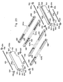
- FIG 14 shows by an exploded view one embodiment of the assembled mother boat constructed in accordance with this invention.
- the illustrated mother boat is comprised of a pair of side plates 402a and 402b, a pair of end plates 404a and 404b, a pair of wheel members 406a and 406b, and an additional part 408.
- Each of the pair of side plates 402a and 402b spaced from each other laterally is of an elongated shape extending in the front and rear directions, preferably of a nearly rectangular cross-sectional shape.
- Supporting notches 410 are formed on the upper surfaces of the opposite end portions of each of the side plates 402a and 402b. Each of the supporting notches 410 may be substantially rectangular.
- each of the side plates 402a and 402b has formed therein two openings 412 spaced from each other at a predetermined distance therebetween in the front and rear directions and extending laterally therethrough. Each of these openings 412 has a circular cross-sectional shape.
- the pair of end plates 404a and 404b spaced from each other in the front and rear directions extend laterally across the pair of side plates 402a and 402b.
- the pair of end plates 404a and 404b also have a nearly rectangular cross-sectional shape.
- Engaging notches 414 are formed on the opposite side portions of the under surface of each of the pair of end plates 404a and 404b, and each of such engaging notches 414 may be substantially rectangular.
- the lateral width w8 of each of the anchoring notches 414 is substantially equal to, or slightly larger than, the thickness tl of each of the side plates 402a and 402b.
- the length in the front and rear directions of each of the notches 410 formed in the side plates 402a and 402b is substantially equal to, or slightly larger than, the thickness t2 of each of the end plates 404a and 404b.
- Each of the pair of wheel members 406a and 406b spaced from each other in the front and rear directions includes a wheel shaft 415 and two wheels 418 mounted rotatably on the shaft 415.
- the shaft 415 has a large-diameter portion 416 and small-diameter portions 420 located on both sides of the large-diameter portion 416.
- Each of the wheels 418 has a hole 421 having an inside diameter corresponding to the outside diameter of the small-diameter portion 420. By inserting the small-diameter portion 420 through the hole 421, the wheel 418 is rotatably mounted on the shaft 415.
- the outside diameter of the small-diameter portion corresponds to the inside diameter of the opening 412 formed in the side plates 402a and 402b.
- the shaft 415 and the two wheels 418 may be formed as a one-piece unit.
- a supporting notch 422 which may be rectangular is formed centrally in the upper surface of the end plate 402 in order to combine the additonal part 408.
- the additional part 408 has a main portion 426 having a vertically extending opening 425 formed therein and a T-shaped engaging portion 428 projecting forwardly from the main portion.
- An engaging notch 430 which may be rectangular is formed in the under surface of the narrowed part of the engaging portion 428.
- the iength I 6 in the front and rear directions of the engaging notch 430 is substantially equal to, or slightly larger than, the thickness t2 of the end plate 404a.
- the lateral width w9 of the supporting notch 422 formed centrally in the upper surface of the end plate 404a is substantially equal to, or slightly larger than, the lateral width w10 of the narrowed part of the engaging portion 428 of the additional part 408.
- the pair of side plates 402a and 402b, the pair of end plates 404a and 404b and the additional part 408 are assembled as shown in Figure 15, and constitute an assembled mother boat.
- the pair of wheel members 406a and 406b are combined with the pair of side plates 402a and 402b by rotatably inserting the free end portions of the small-diameter portions 420 located on both side ends of each of the wheel members 406a and 406b into the corresponding openings 412 formed in the side plates 402a and 402b.
- the wheels 418 in the wheel members 406a and 406b are exactly prevented from being disengaged from the small-diameter portions 420 of the wheel shafts 415.
- the wheel members 406a and 406b are combined rotatably between the side plates 402a and 402b, and the side plates 402a and 402b are supported on both sides of the wheel members 406a and 406b.
- the end plate 404a is combined with one end portion each of the side plates 402a and 402b by engaging the engaging notches 414 formed at both side portions of its under surface with the supporting notches 410 formed on the upper surfaces of one end portions of the side plates 402a and 402b.
- the end plate 404b is combined with the other end portion of each of the side plates 402a and 402b by engaging the supporting notches 414 formed on both side portions of its under surface with the supporting notches 410 formed respectively on the upper surfaces of the other end portions of the side plates 402a and 402b.
- the supporting notches 414 With the supporting notches 410, the relative movement of the side plates 402a and 402b and the end plates 404a and 404b in the front and rear directions and the lateral direction is hampered, and the end plates 404a and 404b are stably supported by the side plates 402a and 402b.
- the additional part 408 is combined with the end plate 404a by engaging the engaging notch 430 formed in the under surface of its engaging portion 428 with the supporting notch 422 formed on the upper surface of the end plate 404a.
- the engaging notch 430 is engaged with the supporting notch 422
- the movement of the additonal part 408 in the front and rear directions and the lateral direction relative to the end plate 404a is prevented, and thus, the additional part 408 is stably supported by the end plate 404a.
- the various component parts constituting the assembled mother boat which has been assembled as above in a disassemblable manner i.e. the side plates 402a and 402b, the end plates 404a and 404b, the wheel members 406a and 406b, and the additional part 408, are preferably made of silicon.
- These various component parts may be made of quartz glass instead of silicon.
- quartz glass it is possible, if desired, to reinforce the quartz glass forming the side paltes 402a and 402b with a reinforcing material such as a metallic material or heat-resistant fibers extending longitudinally in the quartz glass, and thus to increase the strength of the side plates 402a and 402b.
- a plurality of assembled devices of the type described hereinabove each supporting a plurality of wafers may be placed on the assembled mother boat in the front and rear directions in spaced-apart relationship.
- the base portions 8 in the lower surfaces of the end supports 2a and 2b in each device are positioned between the pair of side plates 402a and 402b as shown in Figure 16, and the flat surfaces exisiting on both sides of each base portion 8 at the undersurfaces of the end supports 2a and 2b are brought into contact with the upper surfaces of the pair of side plates 402a and 402b.
- the device can be stably supported on the mother boat.
- abutting blocks may be provided in spaced-apart relationship on the side plates 402a and 402b in the front and rear directions so as to prevent exactly the relative movement of the device with respect to the mother boat in the front and rear directions.
- the mother boat on which a plurality of devices have been placed as required may be put into a substantially horizontally extending lateral diffusion furnace (not shown) by, for example, pushing it forwardly.
- the additional part 408 combined with the:end plate 404 a can be utilized for withdrawing the mother boat from the diffusion furnace after the diffusion treatment.
- the mother boat can be withdrawn from the diffusion furnace by hooking the opening 424 of the additional part 408 with a hook-like part formed at the tip of a withdrawing instrument (not shown) known per se, and pulling the instrument.
- a withdrawing instrument not shown
- the additional part 408 may be omitted, and the mother boat can be withdrawn from the diffusion furnace by hooking a suitable site of the end plate 404a, etc. with the hook-like tip portion of the withdrawing instrument.
- the assembled mother boat When the assembled mother boat is to be cleaned, transported, or otherwise handled, it may, as required, be disassembled into the constituent parts. Such disassembling can be effected very easily by performing the aforesaid assembling operation reversely.
- the assembled mother boat constructed in accordance with this invention achieves substantially the same advantages as already described with regard to the assembled device.
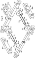
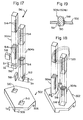
- FIG. 17 shows by an exploded view one embodiment of the assembled device of the invention for supporting semiconductor wafers or the like which can be applied to such a vertical furnace.
- the illustrated device includes one end support 502 and two rods 502a and 502b.
- the end support 502 is in the form of a nearly flat plate. Supporting leg portions 506 and 508 projecting somewhat downwardly are formed in the front edge portion and the rear edge portion of the under surface of the end support 502.
- the main portion of the end support 502 has formed therein two vertically extending openings 510 which are used to cause the two rods 504a and 504b to stand upright on the end support 502 as will be described below.
- Each of the two openings 510 is conveniently of a substantially square cross-sectional shape corresponding to the cross-sectional shape of each of the two rods 504a and 504b, and they are conveniently disposed such that specified corner portions of these openings face each other as shown in Figure 17.
- Each of the two rods 504a and 504b may have a suitable cross-sectional shape such as a circular or polygonal shape. Preferably, it has a rectangular, particularly square, cross-sectional shape from the standpoint of the ease of production and the ease of handling during assembling and disassembling.
- An engaging notch 512 is formed on one surface of the lower end portion of each of the two rods 504a and 504b so as to combine it with the end support 502.
- the engaging notch 512 may be rectangular, and vertical length R 7 is substantially equal to, or slightly larger than, the thickness t3 of the main portion of the end support 502.
- the vertical length 1 8 of a non-notched portion left at the lower end of each of the rods 504a and 504b is adjusted to a value smaller than the amount of downward protrusion of each of the supportint leg portions 506 and 508 of the end support 502.
- the rods 504a and 504b are arrenged such that one corner portion of the former faces one corner portion of the latter.
- a plurality of holding grooves 514 are formed at spaced intervals in the longitudinal direction, i.e. in the vertical direction, on those corner portions of the two rods 504a and 504b which face each other as described above. It is important that the holding grooves 514 formed on the rod 504a should be in lateral alignment with the holding grooves 514 formed on the rod 504b, respectively.
- each of the holding grooves 514 is inclined at a certain angle (for example, an angle of 5 to 10 degrees) in the direction of inserting a wafer or the like into it, i.e. downwardly from the front end to the rear end viewed in the direction shown by an arrow 516 in Figure 17.
- the holding grooves 514 are preferably such that each groove is tapered to provide a gradually decreasing width from its open end to a certain predetermined depth, and has substantially the same width from the aforesaid predetermined depth to its bottom.
- the illustrated device further includes two wedges 518 for use in combining the two rods 504a and 504b fully firmly with the end support.
- the end support 502 and the two rods 504a and 504b are assembled as illustrated in Figure 18 to constitute a device for supporting semiconductor wafers 520 and the like.
- some space is formed along the ohter edge of each of the openings 510, and the wedge 518 is inserted in this space.
- the lower end portions of the two rods 504a and 504b are fully firmly combinded with the end support 502, and the rods 504a and 504b ectend from the end support 502 parallel to each other, desirably substantially vertically upwardly.
- the various component parts constituting the assembled device which has been assembled as above in a disassemblable manner i.e. the end support 502, the two rods 504a and 504b and the two wedges 518, are preferably made of silicon. They may also be formed of quartz glass instead of silicon. In the case of using quartz glass, it is possible, if desired, to reinforce the quartz glass constituting the rods 504a and 504b with a suitable reinforcing material such as a metallic material or heat-resistant fibers extending longitudinally in the quartz glass, and thus to increase the strength of the rods 504a and 504b.
- a suitable reinforcing material such as a metallic material or heat-resistant fibers extending longitudinally in the quartz glass
- a wafer 520 In subjecting a plurality of wafers to a diffusion treatment in a vertical diffusion furnace by utilizing the assembled device, a wafer 520 is moved in the direction of an arrow 516 as shown by the broken line in Figure 18, and inserted in a set of holding grooves 514 in the rods 504a and 504b. In this manner, a plurality of wafers 520 are supported in juxta-position at predetermined intervals in the upward direction. Since as described hereinabove, each of the holding grooves 514 is inclined .downwardly from its forward end to its rear end in the direction shown by the arrow 516, each wafer 520 inserted in the holding groove 514 is positioned in such a state that its free end side is inclined upwardly.
- the wafer 520 is fully prevented from coming out of the holding groove 514 accidentally. It should be noted in this regard that when the holding groove 514 extends substantially horizontally and the wafer 520 inserted in, and supported by, it remains substantially horizontal, there is a great likelihood of the wafer 520 coming out of the holding groove 514 and thus falling from it. Disengagement of the wafer 520 in the direction of arrow 516 can be accurately prevented by making the distance between the holding groove 514 formed in the rod 504 and the corresponding holding member 514 formed in the rod 504 sufficiently smaller than the diameter of the wafer.
- the assembled device is lifted by holding a suitable site of the assembled device, for example the upper ends of the rods 504a and 504b, by means of a suitable suspending device (not shown), and then caused to descend into the vertical diffusion furnace through an opening formed at its upper end, and the end support 502 is placed on the bottom wall of the diffusion furnace.
- a suitable site of the assembled device for example the upper ends of the rods 504a and 504b
- a suitable suspending device not shown
- the assembled device can be withdrawn from the diffusion furnace by raising it with the aforesaid suspending device.
- the assembled device When the assembled device is to be cleaned, transported or otherwise handled, it can as required, be disassembled by performing the aforesaid assembling operation reversely.
- two rods 504a and 504b are used. If desired, however, three or more rods arranged properly may be used.
- wafers supported on it are desirably in such a state that their free end sides incline upwardly, in order to prevent accidental disengagement of the wafers or the like from the assembled device, as already stated above.
- the holding grooves 514 formed in the rods 504a and 504b are inclined downwardly from their in front end to their jn rear end viewed in the drection of inserting or loading wafers as indicated by arrow 516. Accordingly, when the wafers 520 are to be inserted into the holding grooves 514 and withdrawn from the holding grooves 514, it is generally necessary to incline the wafers 520 moved in the direction of arrow 516 in the same way as in the case of inclining the holding grooves 514, namely to incline the wafers downwardly in the direction of arrow 516, and to move the wafers 520 relative to the holding grooves 514.
- an automatic conveying mechanism, etc. known per 6e which are utilized in conveying wafers 520 can move wafers 520 in a substantially vertical state or in a substantially horizontal state, but with such a mechanism, it is considerably diffucult, if not impossible, to move wafers 520 in a state of inclination at a certain angle to the vertical or horizontal direction.
- it is desired to develop an assembled device which can permit wafers to be loaded into and withdrawn from the device by moving them in a substantially vertical state or in a substantially horizontal state, and permit the free end sides of the wafers to be inclined upwardly when the wafers are supported in a diffusion furnace.
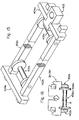
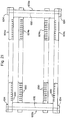
- Figure 20 shows by an exploded view one embodiment of the assembled device constructed in accordance with this invention which meets the above desire.
- the illustrated device includes two end supports 602a and 602b, and four rods 604a, 604b, 604c and 604d.
- Each of the end supports 602a and 602b may be of a suitable shape, but conveniently of a nearly rectangular shape with a large width which enables the end support to stand stably in the state shown in Figure 20.
- Each of the end supports 602a and 602b has a first supporting portion 606 of a relatively narrow width at its lower part, a second supporting portion of a relatively large width at its upper part and an intermediate portion 610 located midway between the first and second supporting portions. At both sides of the intermediate portion 610, a projecting portion 612 projecting sideways beyond the first supporting portion 606 and the second supporting portion 608 is provided.
- a laterally extending channel 614 is formed on the outside surface of the first supporting portion 606, and likewise, a laterally extending channel 616 is formed on the outside surface of the second supporting portion 608.
- the channels 614 and 616 may be of a square cross-sectional shape.
- the upper surface of the projecting portion 612 provided on both sides of the intermediate portion 610 is defined by a horizontal surface 618 and an inclined surface 620.
- the horizontal surface 618 is substantially horizontal
- the inclined surface 620 is inclined downwardly toward the outside surface at a predetermined angle which may be about 5 to 10 degrees.
- the lower surface of the projecting portion 612 is defined by a horizontal surface 622 and an inclined surface 624.
- the horizontal surface 622 is substantially hor i zontal
- the inclined surface 624 is inclined upwardly toward the inside surface at a predetermined angle which may be about 5 to 10 degrees.
- the four rods 604a, 604b, 604c and 604d may have a suitable cross-sectional shape such as a circular or polygonal shape. For the ease of production and the ease of handling in assembling and disassembling, they preferably have a rectangular, especially square, cross-sectional shape.
- Each of the centrally located two rods 604a and 604b has channels 620 formed on the under surfaces of its opposite end portions. Conveniently, each of the channels 626 have substantially the same square cross-sectional shape as the channel 614.
- Each of the two rods 604c and 604d located on both sides has channels 628 formed on the upper surfaces of its opposite ends. Conveniently, the channels 628 have substantially the same square cross-sectional shapes as the channel 616.
- a plurality of holding grooves 630 are formed longitudinally at predetermined intervals on the main portion of each of the four rods 604a, 604b, 604c and 604d. Conveniently, such holding grooves 630 are formed on those corner portions of these rods which are positioned at the inside top end of the rods in the state shown in Figure 20. Each of these holding grooves 630 extends vertically without inclining in the left and right directions in Figure 20. As in the holding grooves 38 and 40 described hereinabove with reference to Figure 4, each of the holding grooves 630 is tapered to provide a gradually decreasing width up to a predetermined depth from its open end, and has substantially the same width from the aforesaid predetermined depth to its bottom. It is important that the substantially same width from the predetermined depth to the bottom should be slightly larger than the thickness of a wafer or the like to be inserted therein.
- the illustrated device further includes four linking shafts 632 and eight stop rings 634, which are used to combine the two opposite end portions of each of the four rods 604a, 604b, 604c and 604d with each of the end supports 602a and 602b detachably and pivotally over a predetermined angular range.
- Each of the four linking shafts 632 conveniently has a circular cross-sectional shape.
- Each of the eight stop rings 634 has formed therein a hole 636 having an inside diameter corresponding to the outside diameter of the linking shaft 632.
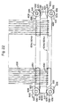
- the two end supports 602a and 602b and the four rods 604a, 604b, 604c and 604d described above are assembled as shown in Figures 21 and 22 to constitute a device for supporting semiconductor wafers 638 or the like.
- the two end supports 602a and 602b are set upright so that they are positioned parallel to each other with a predetermined distance therebetween.
- the end portions of the centrally located rods 604a and 604b are caused to adjoin both side surfaces of the first support portion 606 of each of the end supports 602a and 602b, and the channel 626 formed on the under surface of each of the centrally located rods 604a and 604b is positioned in alignment with the channel 614 formed on the outside surface of the first supporting portion 606.
- the linking shaft 632 is inserted through the channels 614 and 629.
- the opposite end portions of each of the rods 604a and 604b are pivotally combined with the end supports 602a and 602b. Since the linking shaft 632 passes through the channel 626, the linking shaft 632 is prevented from being detached outwardly from the opening surface of the channel 614.
- the linking shaft 632 is prevented from being detached downwardly from the open surface of the channel 626 because the linking shaft 632 passes through the channel 614.
- stop rings 634 are fixed respectively to the opposite ends of the linking shaft 632 projecting laterally beyond the rods 694a and 694b. Fixing of the stop rings 634 to the two opposite ends of the linking shaft 632 can be acheved by, for example, forming a male thread at the opposite ends of the linking shaft 632, forming a female thread in the holes 636 of the stop rings 634, and screwing the stop rings 634 to the opposite ends of the linking shaft 632.
- stop rings 634 are fixed to each of the two ends of the linking shaft 632 projecting laterally beyond the rods 604c and 604d.
- the various components which constitute the assembled device assembled in the above-mentioned manner in a disassembable fashion are preferably made of silicon.
- the various components may also be formed of quartz glass instead of silicon.
- quartz glass it is possible, if desired, to reinforce the quartz glass constituting the rods 604a to 604d and the linking shaft 632 with a metallic material or heat-resistant fibers extending longitudinally in the quartz glass, and to increase the strength of these component parts.
- the device In loading wafers or the like into the device, the device is positioned laterally as illustrated in Figures 21 and 22, namely in the state in which the under surfaces of the first supporting portions 606 of the end supports 602a and 602b are kept in contact with a suitable, substantially horizontal supporting base surface to make the end supports 602a and 602b upstanding.
- the four rods 604a, 604b, 604c and 604d extend substantially horizontally.
- the upper surfaces of the end portions of the centrally located two rods 604a and 604b contact or adjoin the lower horizontal surfaces 622 of the projecting prtions 612 of the end supports 602a and 602b.
- the lower surfaces of the end portions of the two rods 604c and 604d located on both sides contact or adjoin the upper horizontal surfaces 618 of the projecting portions 612 of the end supports 602a and 602b.
- the holding grooves 630 formed on the four rods 604a to 604d should be in lateral alignment as is clearly seen from Figures 21 and 22. It wll be readily seen that when the device is in the laterally laid state, four circumferentially spaced sites of the lower peripheral edge portion of a wafer 638 can be inserted into the four rods 604a, 604b, 604c and 604d by lowering the wafer 638 from above in a substantially vertical condition. Hence, wafers 638 can be automatically loaded into the device very easily.
- the upper end portion of the end support 602b is held by a suitable suspending device (not shown) and the device is lifted as shown by an arrow 640 in Figures 22 and 23.
- a suitable suspending device (not shown)
- at least one hole extending in the thickness direction may be formed, as required, on the upper end portion of the end support 602b.
- the rods 604a, 604b, 604c and 604d extend substantially vertically, but the end supports 604a and 604b incline slightly downwardly from the second supporting portion 608 toward the first supporting portion 606.
- the upper surfaces (those on the right side in Figure 23) of the end portions of the two centrally located rods 602a and 602b make contact with the inclined surfaces 624 on the undersides (left side in Figure 23) of the projecting portions 612 in the end supports 602a and 602b
- the under surfaces (those on the left side in Figure 23) of the end portions of the two rods 604a and 604b located outside make contact with the inclined surfaces 630 on the upper sides (right side in Figure 23) of the projecting portions 612 in the end supports 602a and 602b.
- the end supports 602a and 602b can be prevented from pivoting relative to the rods 604a, 604b, 604c and 604d.
- the end supports 602a and 602b incline slightly downwardly from the second supporting portion 608 toward the first supporting portion 606, the rods 604c and 604d located on both sides deviate slightly upwardly with respect to the centrally located rods 604a and 604b.
- the rods 604c and 604d located forwardly when viewed in the direction of inserting wafers 638 deviates slightly upwardly with respect to the rods 604a and 604b located rearwardly when viewed in the aforesaid direction.
- the holding grooves 630 formed on the rods 604c and 604d deviate slightly upwardly with respect to the holding grooves 630 formed on the rods 604a and 604d.
- the wafers 638 assume a state in which their free end sides incline upwardly. Hence, the wafers 638 are fully prevented from coming out accidentally from the device.
- Such inclination of the wafers 638 is permitted by making the width of each holding groove 630 slightly larger than the thickness of each wafer 638. The device is put into the diffusion furnace while it is in the suspended state, and is maintained in the suspended state in the furnace.
- the device After the diffusion treatment, the device is withdrawn from the diffusion furnace, and then maintained in the laterally laid state shown in Figures 21 and 22. Afterwards, the wafers 638 which have been subjected to diffusion, are taken out from the device.
- the end supports 602a and 602b and the rods 604a, 604b, 604c and 604d relatively pivot over some angular range, and assume the state shown in Figures 21 and 22.
- the wafers 638 return to their substantially vertical state. Accordingly, the wafers 638 can be takne out from the device by raising them substantially vertically, and this operation can be very easily carried out by using an automated system.
- the device is maintained in the laterally laid state shown in Figures 21 and 23 when wafers 638 are loaded into, and taken out from, the device. If desired, the following alternative may be performed.
- the device is maintained suspended when the wafers 638 are loaded into, and taken out from, the device.
- the heights of the holding grooves 630 formed on the rods 604a, 604b, 604c and 604d become substantially the same, and therefore, by moving the substantially horizontally disposed wafers 638 in the substantially horizontal direction, the wafers 638 can be loaded into, and taken out from, the device automatically with sufficient ease.
Landscapes
- Chemical & Material Sciences (AREA)
- Engineering & Computer Science (AREA)
- Crystallography & Structural Chemistry (AREA)
- Materials Engineering (AREA)
- Metallurgy (AREA)
- Organic Chemistry (AREA)
- Container, Conveyance, Adherence, Positioning, Of Wafer (AREA)
Applications Claiming Priority (10)
| Application Number | Priority Date | Filing Date | Title |
|---|---|---|---|
| JP11601982U JPS5920629U (ja) | 1982-07-30 | 1982-07-30 | 拡散治具 |
| JP116019/82U | 1982-07-30 | ||
| JP154780/82 | 1982-09-06 | ||
| JP57154780A JPS5944822A (ja) | 1982-09-06 | 1982-09-06 | ウエ−ハを傾斜支承する拡散治具 |
| JP152174/82U | 1982-10-08 | ||
| JP15217482U JPS5956737U (ja) | 1982-10-08 | 1982-10-08 | 竪型拡散治具 |
| JP169157/82U | 1982-11-08 | ||
| JP16915782U JPS5972726U (ja) | 1982-11-08 | 1982-11-08 | 拡散治具のマザ−ボ−ト |
| JP18034782U JPS5940446Y2 (ja) | 1982-11-29 | 1982-11-29 | 拡散治具 |
| JP180347/82U | 1982-11-29 |
Publications (2)
| Publication Number | Publication Date |
|---|---|
| EP0100539A2 true EP0100539A2 (de) | 1984-02-15 |
| EP0100539A3 EP0100539A3 (de) | 1985-05-22 |
Family
ID=27526709
Family Applications (1)
| Application Number | Title | Priority Date | Filing Date |
|---|---|---|---|
| EP83107498A Withdrawn EP0100539A3 (de) | 1982-07-30 | 1983-07-29 | Zusammengefügte Anordnung zur Halterung von Halbleiterscheiben oder ähnlichem |
Country Status (2)
| Country | Link |
|---|---|
| EP (1) | EP0100539A3 (de) |
| KR (1) | KR920001025B1 (de) |
Cited By (12)
| Publication number | Priority date | Publication date | Assignee | Title |
|---|---|---|---|---|
| GB2166531A (en) * | 1984-11-02 | 1986-05-08 | Heraeus Schott Quarzschmelze | Carrier rack |
| EP0579099A1 (de) * | 1992-07-08 | 1994-01-19 | Daifuku Co., Ltd. | Behälter für scheibenähnliche Gegenstände |
| EP0843338A1 (de) | 1996-11-15 | 1998-05-20 | Upsys | Ein verbesserte Horde zum Trägen von Halbleiterscheiben |
| WO2008106913A3 (de) * | 2007-03-04 | 2008-11-13 | Jonas & Redmann Automationstec | Automatisierungscarrier für substrate, insbesondere wafer zur herstellung siliziumbasierter solarzellen |
| RU2357319C1 (ru) * | 2008-04-23 | 2009-05-27 | Галина Валериановна Скорова | Кассета для групповой диффузионной обработки кремниевых пластин |
| DE102007063017A1 (de) * | 2007-12-21 | 2009-06-25 | Von Ardenne Anlagentechnik Gmbh | Substrathalterung für Gasdiffusionsöfen |
| RU2408949C1 (ru) * | 2010-01-27 | 2011-01-10 | Евгений Александрович Взнуздаев | Кассета для групповой диффузионной обработки полупроводниковых пластин |
| WO2011008753A1 (en) * | 2009-07-13 | 2011-01-20 | Greene, Tweed Of Delaware, Inc. | Chimerized wafer boats for use in semiconductor chip processing and related methods |
| RU2432637C1 (ru) * | 2010-07-22 | 2011-10-27 | Игорь Иванович Зайцев | Кассета диффузионной обработки полупроводниковых пластин |
| RU2432638C1 (ru) * | 2010-07-22 | 2011-10-27 | Игорь Иванович Зайцев | Кассета для жидкостной обработки полупроводниковых пластин |
| RU2555209C1 (ru) * | 2013-12-30 | 2015-07-10 | Федеральное государственное бюджетное образовательное учреждение высшего профессионального образования "Самарский государственный аэрокосмический университет имени академика С.П. Королева (национальный исследовательский университет)" (СГАУ) | Кассета для сплавления элементов силовых полупроводниковых диодов |
| CN115404462A (zh) * | 2022-09-20 | 2022-11-29 | 江苏微导纳米科技股份有限公司 | 基片载具及炉管镀膜设备 |
Family Cites Families (6)
| Publication number | Priority date | Publication date | Assignee | Title |
|---|---|---|---|---|
| JPS5068775A (de) * | 1973-10-19 | 1975-06-09 | ||
| DE2524616A1 (de) * | 1975-06-03 | 1976-12-23 | Siemens Ag | Vorrichtung zum thermischen behandeln von halbleiterscheiben |
| US4053294A (en) * | 1976-05-19 | 1977-10-11 | California Quartzware Corporation | Low stress semiconductor wafer carrier and method of manufacture |
| US4256229A (en) * | 1979-09-17 | 1981-03-17 | Rockwell International Corporation | Boat for wafer processing |
| JPS5688314A (en) * | 1979-12-21 | 1981-07-17 | Hitachi Ltd | Wafer holding jig |
| DE8021868U1 (de) * | 1980-08-16 | 1981-01-29 | Heraeus Quarzschmelze Gmbh, 6450 Hanau | Traegerhorde fuer halbleiterscheiben |
-
1983
- 1983-07-29 EP EP83107498A patent/EP0100539A3/de not_active Withdrawn
- 1983-07-30 KR KR1019830003575A patent/KR920001025B1/ko not_active Expired
Cited By (14)
| Publication number | Priority date | Publication date | Assignee | Title |
|---|---|---|---|---|
| GB2166531A (en) * | 1984-11-02 | 1986-05-08 | Heraeus Schott Quarzschmelze | Carrier rack |
| EP0579099A1 (de) * | 1992-07-08 | 1994-01-19 | Daifuku Co., Ltd. | Behälter für scheibenähnliche Gegenstände |
| US5351836A (en) * | 1992-07-08 | 1994-10-04 | Daifuku Co., Ltd. | Container for plate-like objects |
| EP0843338A1 (de) | 1996-11-15 | 1998-05-20 | Upsys | Ein verbesserte Horde zum Trägen von Halbleiterscheiben |
| WO2008106913A3 (de) * | 2007-03-04 | 2008-11-13 | Jonas & Redmann Automationstec | Automatisierungscarrier für substrate, insbesondere wafer zur herstellung siliziumbasierter solarzellen |
| DE102007063017A1 (de) * | 2007-12-21 | 2009-06-25 | Von Ardenne Anlagentechnik Gmbh | Substrathalterung für Gasdiffusionsöfen |
| DE102007063017B4 (de) * | 2007-12-21 | 2012-03-01 | Von Ardenne Anlagentechnik Gmbh | Substrathalterung für Gasdiffusionsöfen |
| RU2357319C1 (ru) * | 2008-04-23 | 2009-05-27 | Галина Валериановна Скорова | Кассета для групповой диффузионной обработки кремниевых пластин |
| WO2011008753A1 (en) * | 2009-07-13 | 2011-01-20 | Greene, Tweed Of Delaware, Inc. | Chimerized wafer boats for use in semiconductor chip processing and related methods |
| RU2408949C1 (ru) * | 2010-01-27 | 2011-01-10 | Евгений Александрович Взнуздаев | Кассета для групповой диффузионной обработки полупроводниковых пластин |
| RU2432637C1 (ru) * | 2010-07-22 | 2011-10-27 | Игорь Иванович Зайцев | Кассета диффузионной обработки полупроводниковых пластин |
| RU2432638C1 (ru) * | 2010-07-22 | 2011-10-27 | Игорь Иванович Зайцев | Кассета для жидкостной обработки полупроводниковых пластин |
| RU2555209C1 (ru) * | 2013-12-30 | 2015-07-10 | Федеральное государственное бюджетное образовательное учреждение высшего профессионального образования "Самарский государственный аэрокосмический университет имени академика С.П. Королева (национальный исследовательский университет)" (СГАУ) | Кассета для сплавления элементов силовых полупроводниковых диодов |
| CN115404462A (zh) * | 2022-09-20 | 2022-11-29 | 江苏微导纳米科技股份有限公司 | 基片载具及炉管镀膜设备 |
Also Published As
| Publication number | Publication date |
|---|---|
| EP0100539A3 (de) | 1985-05-22 |
| KR840005604A (ko) | 1984-11-14 |
| KR920001025B1 (ko) | 1992-02-01 |
Similar Documents
| Publication | Publication Date | Title |
|---|---|---|
| EP0100539A2 (de) | Zusammengefügte Anordnung zur Halterung von Halbleiterscheiben oder ähnlichem | |
| EP0036859B1 (de) | Wanne zur waferbehandlung | |
| JP4467028B2 (ja) | 縦型ウェーハ支持治具 | |
| US5507873A (en) | Vertical boat | |
| US4801168A (en) | Device for transferring semiconductor wafers | |
| US4403955A (en) | Receptacle for support of a melt containing crucible | |
| JPS60213022A (ja) | 縦型支持具 | |
| JP3157738B2 (ja) | ウエハ移載装置および移載方法 | |
| JPH09237781A (ja) | 熱処理用ボ−ト | |
| US4218214A (en) | Guide wing for a furnace paddle | |
| JP3716874B2 (ja) | 種結晶保持治具 | |
| JP3028767B2 (ja) | T字型種結晶および保持治具 | |
| CN114141675A (zh) | 一种适用不同厚度晶圆的石英舟 | |
| JPH0523583Y2 (de) | ||
| EP0065600B1 (de) | Gestell zum Schnellbrennen keramischer Gegenstände in einem Ofen | |
| JPH053244A (ja) | ウエハ治具 | |
| JPS5940443Y2 (ja) | ウエハ支持装置 | |
| CN214244673U (zh) | 一种螺纹卧式组装硅舟 | |
| JP2000100739A (ja) | 熱処理用ウエハボートおよび熱処理方法 | |
| JP2562683B2 (ja) | 縦型ウェハボ−ト | |
| JPS6169633A (ja) | 薄板体の立替方法及びその立替装置 | |
| JPH0610285Y2 (ja) | 試験片載置台 | |
| JPH0519951Y2 (de) | ||
| JPH05267202A (ja) | ウェーハ支持ボート | |
| JPS60142513A (ja) | 組立式支持具 |
Legal Events
| Date | Code | Title | Description |
|---|---|---|---|
| PUAI | Public reference made under article 153(3) epc to a published international application that has entered the european phase |
Free format text: ORIGINAL CODE: 0009012 |
|
| AK | Designated contracting states |
Designated state(s): DE FR GB IT NL |
|
| PUAL | Search report despatched |
Free format text: ORIGINAL CODE: 0009013 |
|
| AK | Designated contracting states |
Designated state(s): DE FR GB IT NL |
|
| 17P | Request for examination filed |
Effective date: 19850619 |
|
| 17Q | First examination report despatched |
Effective date: 19860520 |
|
| D17Q | First examination report despatched (deleted) | ||
| STAA | Information on the status of an ep patent application or granted ep patent |
Free format text: STATUS: THE APPLICATION HAS BEEN WITHDRAWN |
|
| 18W | Application withdrawn |
Withdrawal date: 19870615 |
|
| RIN1 | Information on inventor provided before grant (corrected) |
Inventor name: SEKIYA, SHINJI |