EP0099904B1 - Sicherungsvorrichtung mit hydraulischer lenkungsblockierung für kraftfahrzeuge - Google Patents
Sicherungsvorrichtung mit hydraulischer lenkungsblockierung für kraftfahrzeuge Download PDFInfo
- Publication number
- EP0099904B1 EP0099904B1 EP83900419A EP83900419A EP0099904B1 EP 0099904 B1 EP0099904 B1 EP 0099904B1 EP 83900419 A EP83900419 A EP 83900419A EP 83900419 A EP83900419 A EP 83900419A EP 0099904 B1 EP0099904 B1 EP 0099904B1
- Authority
- EP
- European Patent Office
- Prior art keywords
- steering
- actuatable
- slide valve
- electric motor
- hydraulic cylinder
- Prior art date
- Legal status (The legal status is an assumption and is not a legal conclusion. Google has not performed a legal analysis and makes no representation as to the accuracy of the status listed.)
- Expired
Links
Images
Classifications
-
- B—PERFORMING OPERATIONS; TRANSPORTING
- B60—VEHICLES IN GENERAL
- B60R—VEHICLES, VEHICLE FITTINGS, OR VEHICLE PARTS, NOT OTHERWISE PROVIDED FOR
- B60R25/00—Fittings or systems for preventing or indicating unauthorised use or theft of vehicles
- B60R25/01—Fittings or systems for preventing or indicating unauthorised use or theft of vehicles operating on vehicle systems or fittings, e.g. on doors, seats or windscreens
- B60R25/02—Fittings or systems for preventing or indicating unauthorised use or theft of vehicles operating on vehicle systems or fittings, e.g. on doors, seats or windscreens operating on the steering mechanism
-
- Y—GENERAL TAGGING OF NEW TECHNOLOGICAL DEVELOPMENTS; GENERAL TAGGING OF CROSS-SECTIONAL TECHNOLOGIES SPANNING OVER SEVERAL SECTIONS OF THE IPC; TECHNICAL SUBJECTS COVERED BY FORMER USPC CROSS-REFERENCE ART COLLECTIONS [XRACs] AND DIGESTS
- Y10—TECHNICAL SUBJECTS COVERED BY FORMER USPC
- Y10T—TECHNICAL SUBJECTS COVERED BY FORMER US CLASSIFICATION
- Y10T70/00—Locks
- Y10T70/50—Special application
- Y10T70/5889—For automotive vehicles
- Y10T70/5956—Steering mechanism with switch
-
- Y—GENERAL TAGGING OF NEW TECHNOLOGICAL DEVELOPMENTS; GENERAL TAGGING OF CROSS-SECTIONAL TECHNOLOGIES SPANNING OVER SEVERAL SECTIONS OF THE IPC; TECHNICAL SUBJECTS COVERED BY FORMER USPC CROSS-REFERENCE ART COLLECTIONS [XRACs] AND DIGESTS
- Y10—TECHNICAL SUBJECTS COVERED BY FORMER USPC
- Y10T—TECHNICAL SUBJECTS COVERED BY FORMER US CLASSIFICATION
- Y10T70/00—Locks
- Y10T70/60—Systems
- Y10T70/625—Operation and control
- Y10T70/65—Central control
Definitions
- the invention relates to a safety device for motor vehicles, which blocks the steering.
- Steering wheel locks that block the steering are the most commonly used and most effective devices to prevent the unauthorized use of motor vehicles.
- the known steering wheel locks are mechanical devices that are attached to the steering column and mechanically lock the steering wheel shaft or the steering wheel.
- the steering wheel lock is easily accessible when the vehicle is open.
- the arrangement of the steering wheel lock on the steering column is unfavorable in terms of comfort, safety, appearance and legal regulations.
- the invention has for its object to eliminate these disadvantages of known steering wheel locks.
- this object is achieved in a safety device of the type mentioned at the outset in that it comprises a device for closing the inlet openings of a hydraulic cylinder, the piston rod of which is connected to a component of the steering.
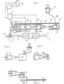
- the hydraulic steering aid of the vehicle consists of a hydraulic cylinder 1, the piston rod 2 of which has a toothing which interacts with a pinion 3.
- the pinion 3 also controls a distributor 4, which is connected to a pump 5 and a reservoir 6.
- the ends of the piston rod 2 interact with the joints 7 of the steering.
- the piston 25 of the hydraulic cylinder 1 divides it into two spaces which are connected to two outlets of the distributor 4 by the left inlet opening 19 and the right inlet opening 20.
- the openings 19 and 20 can be closed, whereby the piston 25 and the piston rod 2 are locked and thus the joints 7 are blocked.
- a simple hydraulic device can be provided, which consists of a hydraulic cylinder 1, the piston rod 2 of which is connected directly to the steering.
- the inlet openings 19, 20 are closed hydraulically.
- the device contains a slide 8 with three pistons 9, 10, 11, which are mounted on a common piston rod 16 and connected to a nut 12.
- the pistons 9 and 10 do not close the respective openings 19 and 20, and the hydraulic cylinder 1 is normally fed through the openings 21 and 23.
- the piston 11 is intended either to interrupt the fuel supply to the engine or to open or close the ignition circuit in such a way that the steering cannot be blocked while the engine is running.
- the nut 12 cooperates with a spindle 13 which is driven by an electric motor 14; the whole is housed in a housing 15.
- the end of the piston rod 16 holds the housing 15 in the rest position.
- the motor 14 is switched on and off by an electrical key switch 17, to which it is connected by an armored cable 18.
- the switch 17 When the switch 17 is turned to the OFF position and the key is removed, the motor 14 is switched on and produces a linear movement of the pistons 9, 10, 11 to the left (in the drawing), which feeds the hydraulic cylinder 1, the fuel supply in the Lines 22, 24 and the ignition circuit 29 is interrupted.
- the vehicle is no longer operational, its steering is blocked in the position it has assumed.
- the motor 14 is switched on again, now turns in the opposite direction and moves the pistons 9, 10, 11 into the position shown in FIG.
- the slide 8 is controlled by an electromagnet 26, which in turn is actuated by the switch 17.
- the slide 8 is moved by a vacuum device 27 against the resistance of a spring 28.
- the slide 8 is mechanically controlled by a lever 30 which is moved by a rope 31 or a linkage.
- the closure of the inlet openings 19, 20 of the hydraulic cylinder can be effected directly by solenoid valves.
- the safety device can also control an injection pump and / or an electrical circuit of the vehicle.
- the securing device can be used by any suitable means such as the described key switch, an electronic access device, an electronic remote control and the like can be operated.
Landscapes
- Engineering & Computer Science (AREA)
- Mechanical Engineering (AREA)
- Lock And Its Accessories (AREA)
Applications Claiming Priority (2)
| Application Number | Priority Date | Filing Date | Title |
|---|---|---|---|
| FR8201310 | 1982-01-28 | ||
| FR8201310A FR2520314A1 (fr) | 1982-01-28 | 1982-01-28 | Antivol de direction a blocage hydraulique pour vehicules automobiles |
Publications (2)
| Publication Number | Publication Date |
|---|---|
| EP0099904A1 EP0099904A1 (de) | 1984-02-08 |
| EP0099904B1 true EP0099904B1 (de) | 1985-11-21 |
Family
ID=9270395
Family Applications (2)
| Application Number | Title | Priority Date | Filing Date |
|---|---|---|---|
| EP83900419A Expired EP0099904B1 (de) | 1982-01-28 | 1983-01-25 | Sicherungsvorrichtung mit hydraulischer lenkungsblockierung für kraftfahrzeuge |
| EP83100634A Pending EP0085383A1 (de) | 1982-01-28 | 1983-01-25 | Sicherungsvorrichtung mit hydraulischer Lenkungsblockierung für Kraftfahrzeuge |
Family Applications After (1)
| Application Number | Title | Priority Date | Filing Date |
|---|---|---|---|
| EP83100634A Pending EP0085383A1 (de) | 1982-01-28 | 1983-01-25 | Sicherungsvorrichtung mit hydraulischer Lenkungsblockierung für Kraftfahrzeuge |
Country Status (6)
| Country | Link |
|---|---|
| US (1) | US4562710A (es) |
| EP (2) | EP0099904B1 (es) |
| DE (1) | DE3361247D1 (es) |
| ES (1) | ES519302A0 (es) |
| FR (1) | FR2520314A1 (es) |
| WO (1) | WO1983002592A1 (es) |
Families Citing this family (15)
| Publication number | Priority date | Publication date | Assignee | Title |
|---|---|---|---|---|
| DE3436761A1 (de) * | 1984-08-31 | 1986-03-13 | Kiekert GmbH & Co KG, 5628 Heiligenhaus | Sicherheitseinrichtung gegen unbefugten betrieb eines kraftfahrzeuges |
| WO1986002051A1 (en) * | 1984-09-28 | 1986-04-10 | Francis Warwick Deuchar | Vehicle steering security system |
| CA1276953C (en) * | 1986-04-02 | 1990-11-27 | Yehuda Baruch | Anti-theft system for vehicles |
| US5003800A (en) * | 1989-07-17 | 1991-04-02 | Phelps-Tointon, Inc. | Door lock control system featuring a remote control for a pneumatically powered door lock mechanism |
| DE59500565D1 (de) * | 1995-01-20 | 1997-10-02 | Siemens Ag | Diebstahlschutzvorrichtung für ein Kraftfahrzeug |
| GB2299614B (en) * | 1995-04-05 | 1998-08-12 | John Harris | Ignition security device |
| DE19617566C2 (de) * | 1996-05-02 | 1998-04-02 | Daimler Benz Ag | Hydraulische Servolenkung eines Kraftfahrzeuges |
| US6501370B1 (en) | 1996-09-16 | 2002-12-31 | Frank G. Rick | Vehicle anti-theft lock apparatus and method |
| US6000489A (en) * | 1996-09-16 | 1999-12-14 | Rick; Frank G. | Anti-theft steering lock |
| US6034442A (en) * | 1997-02-18 | 2000-03-07 | Mostrom; Lloyd C. | Frustrator--Model E |
| DE19733032C1 (de) * | 1997-07-31 | 1998-09-24 | Mercedes Benz Lenkungen Gmbh | Hydraulische Servolenkung mit geschlossener Mitte |
| WO2002062633A1 (en) * | 2001-02-08 | 2002-08-15 | Martin Hansen | Procedure for protection against theft of vehicles and a barring device for the implementation of the procedure |
| US6598393B2 (en) * | 2001-11-01 | 2003-07-29 | Delphi Technologies, Inc. | Anti-theft steering lock |
| GB2446590A (en) * | 2007-02-19 | 2008-08-20 | Greg Sigley | Remote hydraulic immobilizer |
| WO2010151903A1 (en) * | 2009-06-26 | 2010-12-29 | Cubic Corporation | Shipping container active lock release failsafe |
Citations (1)
| Publication number | Priority date | Publication date | Assignee | Title |
|---|---|---|---|---|
| DE2818703A1 (de) * | 1977-05-04 | 1978-11-09 | Crosas Pedro Battle | Diebstahlsicherung fuer kraftfahrzeuge |
Family Cites Families (13)
| Publication number | Priority date | Publication date | Assignee | Title |
|---|---|---|---|---|
| FR745403A (es) * | 1933-05-10 | |||
| US1790427A (en) * | 1931-01-27 | Herbert milbttbit kirton | ||
| US2695685A (en) * | 1949-12-20 | 1954-11-30 | Charles R Jamison | Electrohydraulic theft preventing device |
| US2802674A (en) * | 1955-11-16 | 1957-08-13 | Gen Motors Corp | Roll control system for a motor vehicle |
| DE1818703U (de) * | 1958-08-04 | 1960-09-29 | Walter Geissler | Manschette fuer hemden, blusen u. dgl. |
| US3550717A (en) * | 1968-09-09 | 1970-12-29 | Gulf Oil Corp | Automotive safety devices |
| US3515442A (en) * | 1969-01-21 | 1970-06-02 | Lawrence C Whittemore | Lock for hydraulic brakes of vehicles |
| DE2427258A1 (de) * | 1974-06-06 | 1975-12-18 | Anton Ax | Diebstahlsicherung fuer kraftfahrzeuge |
| US4119171A (en) * | 1975-02-24 | 1978-10-10 | Societe d'Exploitation des Brevets Neiman SA. | Safety anti-theft device for vehicles having a diesel engine |
| DE2742666A1 (de) * | 1977-09-22 | 1979-04-05 | Daimler Benz Ag | Pneumatische betaetigungsanordnung, insbesondere fuer zentralverriegelungsanlagen, und umschaltventil dafuer |
| US4146244A (en) * | 1977-05-31 | 1979-03-27 | The Bendix Corporation | Rack and pinion power steering device |
| US4175635A (en) * | 1978-07-06 | 1979-11-27 | James Thomas | Anti-theft device for internal combustion engine of a motor vehicle |
| JPS57205271A (en) * | 1981-06-12 | 1982-12-16 | Nissan Motor Co Ltd | Flow rate controlling valve of power steering apparatus |
-
1982
- 1982-01-28 FR FR8201310A patent/FR2520314A1/fr active Granted
-
1983
- 1983-01-20 ES ES519302A patent/ES519302A0/es active Granted
- 1983-01-25 EP EP83900419A patent/EP0099904B1/de not_active Expired
- 1983-01-25 US US06/545,389 patent/US4562710A/en not_active Expired - Fee Related
- 1983-01-25 WO PCT/EP1983/000017 patent/WO1983002592A1/en active IP Right Grant
- 1983-01-25 EP EP83100634A patent/EP0085383A1/de active Pending
- 1983-01-25 DE DE8383900419T patent/DE3361247D1/de not_active Expired
Patent Citations (1)
| Publication number | Priority date | Publication date | Assignee | Title |
|---|---|---|---|---|
| DE2818703A1 (de) * | 1977-05-04 | 1978-11-09 | Crosas Pedro Battle | Diebstahlsicherung fuer kraftfahrzeuge |
Also Published As
| Publication number | Publication date |
|---|---|
| EP0099904A1 (de) | 1984-02-08 |
| DE3361247D1 (en) | 1986-01-02 |
| FR2520314A1 (fr) | 1983-07-29 |
| WO1983002592A1 (en) | 1983-08-04 |
| US4562710A (en) | 1986-01-07 |
| EP0085383A1 (de) | 1983-08-10 |
| ES8308775A1 (es) | 1983-10-16 |
| FR2520314B1 (es) | 1984-03-23 |
| ES519302A0 (es) | 1983-10-16 |
Similar Documents
| Publication | Publication Date | Title |
|---|---|---|
| EP0099904B1 (de) | Sicherungsvorrichtung mit hydraulischer lenkungsblockierung für kraftfahrzeuge | |
| DE3303811C2 (es) | ||
| DE19752519A1 (de) | Verriegelungseinrichtung für Lenkungen von Kraftfahrzeugen | |
| DE102009028340A1 (de) | Einrichtung zur Notentriegelung einer Parksperre eines Automatgetriebes eines Kraftfahrzeugs | |
| DE102017108265A1 (de) | Schloss für ein Kraftfahrzeug | |
| DE19957046A1 (de) | Schließsystem, insbesondere für Kraftfahrzeuge | |
| DE2056066A1 (de) | Abschaltventilvorrichtung bei einer Servolenkung für Fahrzeuge | |
| DE2518626C3 (de) | Druckmittelversorgungseinrichtung für hydraulische Hilfskraftlenkungen von Fahrzeugen | |
| DE3443802C2 (es) | ||
| DE60131507T2 (de) | Verriegelungsvorrichtung zum diebstahlschutz einer hydraulikanlage, insbesondere für lastkraftwagen | |
| DE2617798C3 (de) | Als Zylinderschlofl ausgebildete Diebstahlsicherung | |
| DE2504541A1 (de) | Diebstahlsicherung fuer kraftfahrzeuge | |
| DE10307472B4 (de) | Blockiervorrichtung für eine Lenkwelle und Lenkeinrichtung mit dieser Vorrichtung | |
| DE4406836A1 (de) | Neutralstellungs-Startschalter und Sicherungsalarmschalter und ein Verfahren zu deren Montage für eine manuelle Verdrängungssteuerung für einen hydrostatischen Antrieb | |
| DE19852061A1 (de) | Ventilanordnung für Servolenkungen | |
| EP0721869A1 (de) | Verriegelungsvorrichtung für Kraftfahrzeuge | |
| DE3209778A1 (de) | Servolenkhilfe fuer ein fahrzeug | |
| EP1589168A1 (de) | Betätigungsvorrichtung für eine Notentriegelungseinrichtung an Türen für Fahrzeuge des öffentlichen Personen-Nah- und-Fernverkehrs | |
| DE19628149B4 (de) | Einrichtung an einem Kraftfahrzeug mit Heckklappe | |
| DE3118263C2 (de) | Türbetätigungseinrichtung | |
| EP2099991B1 (de) | Kraftfahrzeugtürverschluss | |
| DE10393313B4 (de) | Diebstahlsicherungsvorrichtung für Kraftfahrzeuge mit hydraulischer Servolenkung | |
| EP0836959A1 (de) | Notbetätigungseinrichtung für ein elektrisch betriebenes Schiebedach | |
| DE3122135A1 (de) | Tuerbetaetigungseinrichtung | |
| DE3619642C2 (es) |
Legal Events
| Date | Code | Title | Description |
|---|---|---|---|
| PUAI | Public reference made under article 153(3) epc to a published international application that has entered the european phase |
Free format text: ORIGINAL CODE: 0009012 |
|
| 17P | Request for examination filed |
Effective date: 19830924 |
|
| AK | Designated contracting states |
Designated state(s): DE GB |
|
| RBV | Designated contracting states (corrected) |
Designated state(s): DE GB IT |
|
| XX | Miscellaneous (additional remarks) |
Free format text: VERBUNDEN MIT 83100634.1/0085383 (EUROPAEISCHE ANMELDENUMMER/VEROEFFENTLICHUNGSNUMMER) DURCH ENTSCHEIDUNG VOM 20.03.85. |
|
| GRAA | (expected) grant |
Free format text: ORIGINAL CODE: 0009210 |
|
| ITF | It: translation for a ep patent filed |
Owner name: FUMERO BREVETTI S.N.C. |
|
| AK | Designated contracting states |
Designated state(s): DE GB IT |
|
| XX | Miscellaneous (additional remarks) |
Free format text: VERBUNDEN MIT 83100634.1/0085383 (EUROPAEISCHE ANMELDENUMMER/VEROEFFENTLICHUNGSNUMMER) DURCH ENTSCHEIDUNG VOM 20.03.85. |
|
| REF | Corresponds to: |
Ref document number: 3361247 Country of ref document: DE Date of ref document: 19860102 |
|
| PLBE | No opposition filed within time limit |
Free format text: ORIGINAL CODE: 0009261 |
|
| STAA | Information on the status of an ep patent application or granted ep patent |
Free format text: STATUS: NO OPPOSITION FILED WITHIN TIME LIMIT |
|
| 26N | No opposition filed | ||
| ITPR | It: changes in ownership of a european patent |
Owner name: CAMBIO RAGIONE SOCIALE;SOCIETE DE PARTECIPATIONS N |
|
| ITTA | It: last paid annual fee | ||
| PGFP | Annual fee paid to national office [announced via postgrant information from national office to epo] |
Ref country code: GB Payment date: 19961223 Year of fee payment: 15 |
|
| PGFP | Annual fee paid to national office [announced via postgrant information from national office to epo] |
Ref country code: DE Payment date: 19970321 Year of fee payment: 15 |
|
| PG25 | Lapsed in a contracting state [announced via postgrant information from national office to epo] |
Ref country code: GB Free format text: LAPSE BECAUSE OF NON-PAYMENT OF DUE FEES Effective date: 19980125 |
|
| GBPC | Gb: european patent ceased through non-payment of renewal fee |
Effective date: 19980125 |
|
| PG25 | Lapsed in a contracting state [announced via postgrant information from national office to epo] |
Ref country code: DE Free format text: LAPSE BECAUSE OF NON-PAYMENT OF DUE FEES Effective date: 19981001 |