EP0099467B1 - Chariot élévateur à fourche transversale - Google Patents
Chariot élévateur à fourche transversale Download PDFInfo
- Publication number
- EP0099467B1 EP0099467B1 EP83105751A EP83105751A EP0099467B1 EP 0099467 B1 EP0099467 B1 EP 0099467B1 EP 83105751 A EP83105751 A EP 83105751A EP 83105751 A EP83105751 A EP 83105751A EP 0099467 B1 EP0099467 B1 EP 0099467B1
- Authority
- EP
- European Patent Office
- Prior art keywords
- frame
- axle
- loading
- steering
- rams
- Prior art date
- Legal status (The legal status is an assumption and is not a legal conclusion. Google has not performed a legal analysis and makes no representation as to the accuracy of the status listed.)
- Expired
Links
Images


Classifications
-
- B—PERFORMING OPERATIONS; TRANSPORTING
- B66—HOISTING; LIFTING; HAULING
- B66F—HOISTING, LIFTING, HAULING OR PUSHING, NOT OTHERWISE PROVIDED FOR, e.g. DEVICES WHICH APPLY A LIFTING OR PUSHING FORCE DIRECTLY TO THE SURFACE OF A LOAD
- B66F9/00—Devices for lifting or lowering bulky or heavy goods for loading or unloading purposes
- B66F9/06—Devices for lifting or lowering bulky or heavy goods for loading or unloading purposes movable, with their loads, on wheels or the like, e.g. fork-lift trucks
- B66F9/075—Constructional features or details
- B66F9/08—Masts; Guides; Chains
- B66F9/10—Masts; Guides; Chains movable in a horizontal direction relative to truck
-
- B—PERFORMING OPERATIONS; TRANSPORTING
- B66—HOISTING; LIFTING; HAULING
- B66F—HOISTING, LIFTING, HAULING OR PUSHING, NOT OTHERWISE PROVIDED FOR, e.g. DEVICES WHICH APPLY A LIFTING OR PUSHING FORCE DIRECTLY TO THE SURFACE OF A LOAD
- B66F9/00—Devices for lifting or lowering bulky or heavy goods for loading or unloading purposes
- B66F9/06—Devices for lifting or lowering bulky or heavy goods for loading or unloading purposes movable, with their loads, on wheels or the like, e.g. fork-lift trucks
- B66F9/075—Constructional features or details
- B66F9/07586—Suspension or mounting of wheels on chassis
Definitions
- the invention relates to a cross-lift truck according to the preamble of claim 1.
- Cross-lift trucks of this type (DE-B-19 53 112) are designed and constructed so that the overall center of gravity, which results from the weight of the vehicle frame and body and the maximum load absorbed , lies approximately in the median longitudinal plane. Since the center of gravity of the load inevitably comes to lie laterally offset with respect to the median longitudinal plane of the vehicle, the center of gravity of the vehicle body without load on the side of the median plane of the vehicle facing away from the direction of travel of the mast is likewise offset to this. This results in different positions of the respective center of gravity, which lead to different wheel pressures, depending on the loading condition of the cross-truck.
- a three-point support of the frame is provided on the chassis, one support point each above the steering axis and the driving axis, while a third, imaginary supporting point between the steering axis and the driving axis in the line of connection between the two on this side of the forklift is arranged double-acting hydraulic presses, which are connected in parallel to each other.
- Another design (GB-A-910 236) provides a travel frame mounted on springs, in which floor supports are provided on the load side when the load is to be extended laterally. It is not possible to move the vehicle in this position. The springs on the side facing away from the load are greatly relieved when the load is extended, despite the supports, so that the vehicle with its body and lifting mast tilts towards the load side.
- hydraulic cylinders are arranged next to the springs opposite the load, which have the task of holding the springs in their position when the load is shifted. However, these cylinders are not acted upon and only have a positioning function. They are only blocked when the vehicle is stationary. The driving behavior is therefore not affected.
- the invention is based on the object of designing a transverse forklift truck of the type mentioned at the outset in such a way that a favorable wheel pressure distribution with respect to the drive axle is ensured in all load ranges if possible.
- the drive axle is provided on the side facing the extension side of the slide with the self-aligning bearing and the steering axle with a further double-acting hydraulic press, with the hydraulic circuit in an operating state up to a certain load this further press is rendered ineffective and the other two presses are blocked, and in another operating state with greater load the further press is blocked and the other two presses are connected in parallel.
- this further press is rendered ineffective and the other two presses are blocked, and in another operating state with greater load the further press is blocked and the other two presses are connected in parallel.
- there are two fundamentally different supports between the frame and the undercarriage which are particularly suitable, one for empty travel and one for travel with maximum coverage.
- transverse forklift trucks shown in FIGS. 1 to 4 basically have the same structure and differ only with regard to the suspension of the undercarriage, the steering axle being provided with a different type of pendulum mounting in FIGS. 3, 4.
- the transverse forklifts have a U-shaped frame in plan view, between the legs 17 and 18 of which a lifting mast 9 can be extended to the side with a carriage, not shown, which carries a load fork 19.
- the lifting mast 9 can be completely retracted together with the load fork 19 into the frame 1 of the forklift.
- the load picked up or released by the load fork is deposited on the legs 17 and 18 during the process.
- the frame On the side facing away from the load fork, the frame is provided with a driver's cab in the area of a front corner point in a manner not shown.
- the 1 and 2 contains a steering axle 2 with two steered wheels 13 and 16 and a drive axle 3 with the drive wheels 14 and 15.
- the drive axle 3 is designed as a pendulum axle, which with a self-aligning bearing, one in the vehicle longitudinal direction has pointing axis of rotation, is mounted on the frame.
- This self-aligning bearing 20 is located relatively close to the load-side drive wheel 15.
- the oscillating axis is additionally supported on the frame 1 by a hydraulic press 7.
- the vertical forces are absorbed by the hydraulic press 7 and the self-aligning bearing 20, while all other forces, such as horizontal forces, lateral forces and torsional forces, are absorbed by the self-aligning bearing 20 alone.
- a drive motor is provided in a manner not shown, which is connected in a known manner to the drive wheels 14 and 15 via a gear and a differential.
- the steering axle 2 consists of an axle body on which the steered wheels 13 and 16 are arranged so as to be pivotable about vertical axes.
- the axle body is supported in the vicinity of the steered wheels 13 and 16 in the vertical direction on the frame 1 under the leg 17 by means of two double-acting hydraulic presses 6 and 8.
- the longitudinal forces, transverse forces and torsional forces are absorbed by longitudinal links 11 and a transverse link, not shown in FIGS. 1 and 2, which will be described in more detail later in connection with FIGS. 5 and 6.
- the frame 1 is thus supported below the leg 17 on the steering axle 2 and below the leg 18 on the driving axle 3.
- the double-acting press 8 on the extension direction of the mast 9 and thus the load side is blocked, d. H. blocked against the supply or discharge of pressure medium, so that a rigid connection at the point of the press 8 between the steering axis 2 and the frame 1 is given.
- the working spaces of the presses 6 and 7, which are arranged on the side facing away from the load, are connected in parallel with one another. For this purpose, their working spaces are hydraulically connected to one another, as will be explained in more detail later with reference to FIG. 8.
- an imaginary support point B is thus formed between the frame 1 and the chassis.
- the exact position of the support point B is determined by the ratio of the piston surfaces of the presses 6 and 7 and can therefore be selected in terms of design.
- the self-aligning bearing 20 forms a further rigid support between the drive axle 3 and the frame 1.
- the support is changed by switching the presses 6, 7 and 8, so that there is a support according to FIG. 2.
- the double-acting press 8 is emptied, ie both working spaces are opened to form a tank, as will be described in more detail with reference to FIG. 8.
- the presses 6 and 7 are separated and blocked, so that they become rigid supports.
- the steering axis 2 thus becomes a kind of pendulum axis which is rigidly supported on the frame 1 by the press 6. Since the blocked press 7 also results in a rigid support, the driving axle 3 is connected to the frame 1 in a completely rigid manner.
- the drive wheels 14 and 15 thus form support points E and F for the frame on the road.
- a third support point D is formed by the press 6 on the steering axle 6.
- the extended connecting line between the press 6 and thus the support point D and the center of gravity S 1 in the unloaded state runs approximately through the longitudinal center of the driving axle 3, so that a uniform distribution of the wheel pressure is ensured when the vehicle is unladen.
- the focus S 1 lies at a clear distance from the connecting lines D, E and D, F, which are to be regarded as tilting lines. This type of support also results in very high cornering stability.
- the existing three-point support according to FIG. 2 offers advantages not only when the forklift is unladen, but also over a relatively large load range.
- a switchover to the support according to FIG. 1 can expediently be carried out in the range between 50 and 70% of the maximum load. The exact values depend on the exact location of the focal points S 1 and S 2 , which result from the design.
- the switch between the two types of support according to FIGS. 1 and 2 can be carried out by the operator by hand or can be controlled automatically via an additional device which detects the load condition.
- a switchover device 10 ensures that the type of support according to FIG. 1 is always present between the frame and the undercarriage when the mast 9 is extended laterally.
- the switching device which can be an electrical switch, for example, is arranged between the frame 1 and the lifting mast 9 or the carriage, not shown, that a forced switching to the support type according to FIG. 1 always takes place when the lifting mast is extended laterally becomes. Switching to the type of support according to FIG. 2 is only possible when the lifting mast 9 is at least approximately completely retracted.
- the steering axis 4 and the driving axis 5 are designed as real pendulum axles, which have self-aligning bearings 21 and 22 on the side facing away from the load, that is to say the side opposite the extension direction of the slide, between the steering axis 4 and the frame 1 and between the drive shaft 5 and the frame 1 are arranged.
- These self-aligning bearings 21 absorb the vertical, longitudinal, transverse and torsional forces.
- the steering axle 4 and the driving axle 5 are additionally supported on the load-facing side with double-acting hydraulic presses 6 and 7 with respect to the frame 1, the working spaces of which are hydraulically connected to one another, so that these two presses 6 and 7 are connected in parallel.
- the type of support according to FIG. 3 ensures a good distribution of the wheel pressure to the drive wheels 14 and 15 at maximum load, in which an overall center of gravity S 2 is established close to the longitudinal center plane of the vehicle.
- the center of gravity S 1 of the body is at a relatively large distance from the body when the cross-truck is not loaded Longitudinal center plane of the vehicle, so that an unfavorable wheel pressure distribution also arises here.
- a special circuit for the hydraulic presses 6 and 7 is also provided here, so that it is possible to switch to the type of support according to FIG Support type according to Fig. 2 is identical.
- the double-acting press 6 is emptied, so that the steering axle 4 is supported alone in the self-aligning bearing 21 at point K.
- the press 7, on the other hand, is blocked so that it forms a rigid support between the driving axis 5 and the frame 1. 2 there is a rigid support of the drive axle on both sides by means of the self-aligning bearing 22 and the press 7 and a rigid support in the self-aligning bearing 21 of the steering axle 4.
- This results in a support in the three points K, L and M. which corresponds to the support in points D, E and F according to FIG. 2.
- the presses 6 and 8 of the two embodiments open up additional adjustment options with which it is possible to adapt to the existing conditions when picking up or when placing a load. It is possible to press 6 and 8 simultaneously supply or discharge a print medium, while the supply to the press 7 is then interrupted. This makes it possible to raise or lower the frame 1 about the driving axis 3, so that the load fork 19 and the lifting mast 9 also rotate accordingly. It is also possible, in the embodiment of FIGS. 1 and 2, to simultaneously supply or discharge the presses 6 and 7, so that the frame 1 is then pivoted about the connecting line of the load-side support points A and C, which leads to a corresponding inclination of the load fork 19 and the mast 9 leads.
- the presses 6 and 7 arranged on the load side can be raised or lowered together by supplying or removing pressure medium, which leads to an inclination of the frame 1 around the connecting line of the support points G and H of the load-facing side and thus leads to a corresponding inclination of the fork 19 and the mast 9.
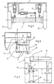
- FIG. 7 shows a construction of a suspension of the driving axle 3 for an exemplary embodiment corresponding to FIGS. 1 and 2.
- the load-side drive wheel 15 is rigidly suspended on a part of the frame 1 below the leg 18.
- the driving wheel 14, on the other hand, is movably attached to the frame 1 in the vertical direction and is supported in the vertical direction by a double-acting hydraulic press 7.
- the hydraulic press 7 is articulated on a wheel carrier 23 which receives the drive wheel 14 and is supported by two longitudinal and transverse links 24 arranged one above the other in a parallelogram arrangement.
- the plate-shaped longitudinal and cross members 24 are each mounted on the frame 1 and the wheel carrier 23 about horizontal axes 25 and 26 running transversely to the vehicle longitudinal direction. This results in an independent wheel suspension which behaves in relation to the support of the drive axle on the frame in accordance with the drive axle 3 designed as a pendulum axle.
- the drive wheel 14 can also be rigidly connected to the frame 1.
- a drive axle 5 can also be designed for the exemplary embodiment according to FIGS. 3 and 4.
- the steering axle 2 is suspended on the frame 1 in addition to the double-acting hydraulic presses 6 and 8 via trailing arms 11 and at least one wishbone 12, which are shown in more detail in FIGS. 5 and 6.
- the trailing arms 11 consist of at least three longitudinal struts 27 which extend in the longitudinal direction of the vehicle and which are articulated parallel to one another on the axle body of the steering axle 2 and two parts 28 of the frame 1 in a parallelogram arrangement.
- a double-acting hydraulic press 12 serves as a control arm, which is arranged between a part 29 of the frame 1 and a holder 30 fastened to the axle body of the steering axle 2.
- the hydraulic presses 6 and 8 and the trailing arms 11 are expediently provided with joints which can be moved on all sides in the form of ball joints or universal joints or the like, so that there is an additional possibility of adjustment by means of the hydraulic press 12.
- the frame 1 By supplying pressure medium into one of the two working chambers of the hydraulic press 12, the frame 1 can be pivoted relative to the steering axis 2 about an imaginary vertical axis lying in the region of the driving axis. This makes it possible to quickly and easily align the entire frame 1 and thus also the load fork 19 and the lifting mast 9 exactly parallel to the stack if it is not approached precisely.
- the hydraulic presses 6 and 8 pivot by the angle ⁇ according to FIG. 5. With this design of the trailing arms 11 and the wishbones 12 according to FIG.
- Fig. 8 a hydraulic circuit is shown, through which the switching of the support types according to Fig. 1 and 2 and the multiple pivoting of the frame relative to the chassis is possible.
- a motor M drives a pump 32, which sucks the hydraulic medium from a reservoir 33 and under pressure via a distributor 34, to which other consumers can be connected, via valves 35, 36, 37 to the individual presses 6, 7, 8 and 12 feeds.
- the valves 35, 36, 37 which are designed as electromagnetically actuated multi-way valves, the supply of pressure medium is interrupted.
- a valve 40 is arranged, which is shown in FIG Position interrupts the connection and releases the connection in its second position. In the position shown, the outflow of pressure medium from the working spaces of the press 7 is blocked, which is arranged on the side of the drive shaft facing away from the load.
- This press thus creates a rigid connection between the drive axle 3 and the frame 1.
- the valve 37 controlling the feed to the presses 6 and 7 is also in the closed position, so that the working spaces of the double-acting press 6 are also closed to the supply and discharge of pressure medium, ie. H. the press 6 is blocked.
- the working spaces of the press 8 are connected to the reservoir 33 in the position shown via a valve 41.
- the press 12 serving as a wishbone is filled with pressure medium in both work spaces and blocked by the valve 35 in the position shown. 2, in which the driving axle is connected to the frame by two rigid supports, while the steering axis is connected to the frame 1 with a rigid support via the press 6 on the side facing away from the load is supported.
- the two working spaces of the press 8 are short-circuited via the valve 41 so that it does not absorb or emit any force and follows every movement of the steering axis 2 in the vertical direction.
- additional lines with check valves 42 and 43 are provided which lead to the reservoir 33 and which accordingly allow oil to be dispensed or sucked in, depending on the direction of piston movement.
- the switching position shown in Fig. 8 thus corresponds to the type of support according to Fig. 2, in which the drive axle 3 is supported on the frame with two rigid supports and the steering axis 2 on the side facing away from the load via the press 6 also with a rigid support on the frame is supported.
- valves 40 and 41 are actuated. This can be done manually or by a load-dependent actuation, which actuates the corresponding solenoid valves 40 and 41.
- the valves 40 and 41 are switched from the position shown to the other position by the switching device 10. In this position, the respective working spaces of the presses 6 and 7 are connected to one another, while the working spaces of the press 8 are blocked via the valve 36. The parallel presses 6 and 7 then form the support point B (Fig. 1), while the press 8 then forms a rigid support point A.
- valve 37 In order to tilt the frame around the axis formed by the two support points A and C, the valve 37 is actuated together with the valves 40 and 41. The presses 6 and 7 can then be raised or lowered, depending on the position of the valve 37.
- valve 36 In order to incline the frame around the driving axis 3, the valve 36 is connected in series with the valve 37, while the valve 40 is then brought into the position shown, in which the press 7 is blocked.
- the valve 41 connects the press 8 to the valve 36.
- valve 35 is actuated, which acts on the press 12.
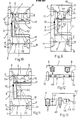
- FIGS. 9 and 10 differs from the embodiment according to FIGS. 1 and 2 by a simplified construction of the steering axis 2. With the exception of the pivoting possibilities of the frame 1 with respect to the longitudinal axis of the vehicle, the same functions are obtained, so that this refers to the description the embodiment of FIGS. 1 and 2 can be referenced.
- a longitudinal link 44 is rigidly attached to the axle body of the steering axle 2 and is located on the side facing the extension direction of the lifting mast 9, which is gimbally suspended on the frame.
- trailing arms 11 are provided both on the axle body and on the frame 1 on the opposite side, which are articulated both on the axle body and on the frame 1.
- Double-acting hydraulic presses 6 and 8 are provided as vertical supports of the steering axle 2 to the frame, one of which, depending on the operating state, is blocked as a rigid support.
- the steering axis 2 executes pendulum movements about pendulum axes 52 or 53, which run obliquely to the longitudinal direction of the vehicle and which are determined by the respective rigid support and the articulation point of the trailing arm 44 on the frame 1.
- the hydraulic presses 6 and 7 When traveling from approximately half to full load, the hydraulic presses 6 and 7 are connected in parallel. The hydraulic press 8 is blocked, so that the steering axis then carries out pendulum movements about the inclined pendulum axis 53 of FIG. 9.
- the hydraulic press 8 When driving empty and driving up to about half the load, the hydraulic press 8 is rendered ineffective, while the hydraulic presses 6 and 7 are blocked, so that the support according to FIG. 10 then results, the steering axis 2 being opposite to the pendulum axis 53 the vehicle longitudinal axis inclined pendulum axis 52 oscillates.
- the hydraulic press 8 can be rendered ineffective, for example, in accordance with the hydraulic circuit shown in FIG. 13.
- the two working spaces of the hydraulic press 8 are connected to a reservoir 51 via lines and a valve 46.
- Check valves 47, 48, 49 and 50 are arranged in the lines in such a way that in the position of the valve 46 shown, the two working spaces of the press 8 are connected to one another, with a volume compensation corresponding to the volume of the piston rod is made possible.
- the hydraulic press 8 is free and ineffective in this position.
- the working spaces of the hydraulic press 8 are separated from one another and also from the reservoir 51, so that the press 8 is blocked and acts as a rigid support.
- the construction of the steering axle has been modified compared to the embodiment according to FIGS. 9 and 10 in that a longitudinal link 45 rigidly suspended on the axle body of the steering axle 2 and gimbally on the frame 1 on the extension direction of the lifting mast 9 is arranged opposite side, while additional, both on the axle body of the steering axle 2 and the frame gimbaled longitudinal link 11 are arranged on the opposite side.
- This design corresponds in principle to the embodiment according to FIGS. 9 and 10 and thus also to the embodiment according to FIGS. 1 and 2, but in the two different operating states (in FIG.
- FIG. 11 Another principle has been implemented in the embodiment according to FIG. 11, with which the hydraulic press 8 can be rendered ineffective.
- This principle can of course also be used in the embodiments according to FIGS. 1 and 2 and 9 and 10.
- the hydraulic press 8 is not firmly connected to the axle body of the steering axle 2 in the embodiment according to FIG. 12, but rather is supported by a spherical plate 54 on the axle body, which is expediently provided with a corresponding bowl-shaped plate made of plastic or the like that is not shown.
- the hydraulic press 8 When driving empty and driving up to about half the load, the hydraulic press 8 is rendered ineffective in that the piston is retracted and the spherical plate 54 is lifted off the axle body of the steering axle 2.
Landscapes
- Engineering & Computer Science (AREA)
- Transportation (AREA)
- Structural Engineering (AREA)
- Civil Engineering (AREA)
- Life Sciences & Earth Sciences (AREA)
- Geology (AREA)
- Mechanical Engineering (AREA)
- Forklifts And Lifting Vehicles (AREA)
- Vehicle Body Suspensions (AREA)
- Body Structure For Vehicles (AREA)
Claims (8)
Priority Applications (1)
| Application Number | Priority Date | Filing Date | Title |
|---|---|---|---|
| AT83105751T ATE23514T1 (de) | 1982-07-22 | 1983-06-11 | Quergabelstapler. |
Applications Claiming Priority (2)
| Application Number | Priority Date | Filing Date | Title |
|---|---|---|---|
| DE3227398A DE3227398A1 (de) | 1982-07-22 | 1982-07-22 | Quergabelstapler |
| DE3227398 | 1982-07-22 |
Publications (3)
| Publication Number | Publication Date |
|---|---|
| EP0099467A2 EP0099467A2 (fr) | 1984-02-01 |
| EP0099467A3 EP0099467A3 (en) | 1984-06-06 |
| EP0099467B1 true EP0099467B1 (fr) | 1986-11-12 |
Family
ID=6169051
Family Applications (1)
| Application Number | Title | Priority Date | Filing Date |
|---|---|---|---|
| EP83105751A Expired EP0099467B1 (fr) | 1982-07-22 | 1983-06-11 | Chariot élévateur à fourche transversale |
Country Status (3)
| Country | Link |
|---|---|
| EP (1) | EP0099467B1 (fr) |
| AT (1) | ATE23514T1 (fr) |
| DE (2) | DE3227398A1 (fr) |
Families Citing this family (3)
| Publication number | Priority date | Publication date | Assignee | Title |
|---|---|---|---|---|
| DE3320954A1 (de) * | 1983-06-10 | 1984-12-13 | Albert Irion Nachf., 7000 Stuttgart | Quergabelstapler |
| DE202012100213U1 (de) | 2012-01-20 | 2013-04-23 | Hubtex Maschinenbau Gmbh & Co. Kg | Flurförderzeug |
| DE102017103024A1 (de) | 2017-02-15 | 2018-08-16 | Hubtex Maschinenbau Gmbh & Co. Kg | Flurförderzeug |
Family Cites Families (6)
| Publication number | Priority date | Publication date | Assignee | Title |
|---|---|---|---|---|
| DE868963C (de) * | 1951-02-15 | 1953-03-02 | Miag Fahrzeugbau G M B H | Feststellvorrichtung fuer die Pendelachsen von Kranfahrzeugen |
| GB910236A (en) * | 1959-06-12 | 1962-11-14 | Rudolf Hauser | Improvements in and relating to side loading fork lift trucks |
| DE1431696A1 (de) * | 1965-12-20 | 1969-01-02 | Irion & Vosseler | Flurfoerdergeraet |
| AT283197B (de) * | 1968-04-18 | 1970-07-27 | Wagner Appbau Ernst | Hubstapler, Transportfahrzeug od.dgl. |
| DE1953112A1 (de) * | 1969-10-22 | 1971-04-29 | Irion & Vosseler | Einrichtung fuer Seitenlader mit querverschiebbarem Hubmast |
| DE1954208C3 (de) * | 1969-10-28 | 1973-10-31 | Kurt 8560 Lauf Steinert | Front und Seitenlader mit einem freitragend verschiebbaren und um eine vertikale Schwenkachse schwenkbaren Hub mast |
-
1982
- 1982-07-22 DE DE3227398A patent/DE3227398A1/de not_active Withdrawn
-
1983
- 1983-06-11 EP EP83105751A patent/EP0099467B1/fr not_active Expired
- 1983-06-11 AT AT83105751T patent/ATE23514T1/de not_active IP Right Cessation
- 1983-06-11 DE DE8383105751T patent/DE3367581D1/de not_active Expired
Also Published As
| Publication number | Publication date |
|---|---|
| DE3227398A1 (de) | 1984-01-26 |
| EP0099467A2 (fr) | 1984-02-01 |
| DE3367581D1 (en) | 1987-01-02 |
| ATE23514T1 (de) | 1986-11-15 |
| EP0099467A3 (en) | 1984-06-06 |
Similar Documents
| Publication | Publication Date | Title |
|---|---|---|
| DE60128599T2 (de) | Arbeitsgerät | |
| DE3904798C2 (fr) | ||
| EP0071796B1 (fr) | Véhicule articulé avec contrepoids déplacable transversalement | |
| EP0266785B1 (fr) | Véhicule automobile polyvalent | |
| DE3302998C2 (de) | Radaufhängung für in den Fahrzeugkörper einschwenkbare Räder bzw. Radachsen | |
| DE212013000022U1 (de) | Anordnung in einer Forstmaschine und mit dementsprechender Anordnung ausgerüstete Forstmaschine | |
| EP0909854A2 (fr) | Véhicule chargeur | |
| DE2849104A1 (de) | Zusatz-lastentraegergeraet | |
| DE2405292A1 (de) | Hydrauliksystem zum steuern einer von einem lastwagen getragenen vorrichtung | |
| DE2149410A1 (de) | Vorder- und Seitenladevorrichtung | |
| EP0439837A1 (fr) | Chariot à fourche | |
| EP0045398B1 (fr) | Dispositif combiné pour échanger et basculer des superstructures de véhicule utilitaire | |
| DE3511336A1 (de) | Auf raedern fahrbare baumaschine mit knicklenkung, wie schaufellader, planierfahrzeug o.dgl. | |
| DE60103741T2 (de) | Radaufhängungsanordnung für eine arbeitsmaschine | |
| EP0099467B1 (fr) | Chariot élévateur à fourche transversale | |
| DE2905236B2 (de) | Fahrzeug zum Transport von Gütern | |
| DE4238248A1 (fr) | ||
| DE4038772C2 (de) | Nutzfahrzeug mit einer schwenkbaren Fahrerkabine | |
| EP3560885A1 (fr) | Chariot de manutention | |
| DE4226936C1 (de) | Flurförderzeug, insbesondere fahrerloses Fahrzeug | |
| DE1430694C3 (de) | Stutzradanordnung fur ein Beton mischfahrzeug | |
| DE3405502A1 (de) | Fahrzeug mit geraet zum aufnehmen, kippen und/oder absetzen von behaeltern oder dgl. | |
| EP0286576B1 (fr) | Véhicule de transport | |
| DE2252821B2 (de) | Ladefahrzeug mit einer lasthebeeinrichtung | |
| DE3016157C2 (de) | Regalstapler für große Hubhöhen |
Legal Events
| Date | Code | Title | Description |
|---|---|---|---|
| PUAI | Public reference made under article 153(3) epc to a published international application that has entered the european phase |
Free format text: ORIGINAL CODE: 0009012 |
|
| AK | Designated contracting states |
Designated state(s): AT CH DE FR GB IT LI |
|
| PUAL | Search report despatched |
Free format text: ORIGINAL CODE: 0009013 |
|
| AK | Designated contracting states |
Designated state(s): AT CH DE FR GB IT LI |
|
| 17P | Request for examination filed |
Effective date: 19840822 |
|
| RAP1 | Party data changed (applicant data changed or rights of an application transferred) |
Owner name: ALBERT IRION NACHFOLGER |
|
| RAP1 | Party data changed (applicant data changed or rights of an application transferred) |
Owner name: KALMAR IRION VIERWEGE- UND QUERSTAPLER GMBH |
|
| GRAA | (expected) grant |
Free format text: ORIGINAL CODE: 0009210 |
|
| ITF | It: translation for a ep patent filed |
Owner name: JACOBACCI & PERANI S.P.A. |
|
| AK | Designated contracting states |
Kind code of ref document: B1 Designated state(s): AT CH DE FR GB IT LI |
|
| REF | Corresponds to: |
Ref document number: 23514 Country of ref document: AT Date of ref document: 19861115 Kind code of ref document: T |
|
| REF | Corresponds to: |
Ref document number: 3367581 Country of ref document: DE Date of ref document: 19870102 |
|
| ET | Fr: translation filed | ||
| PLBE | No opposition filed within time limit |
Free format text: ORIGINAL CODE: 0009261 |
|
| STAA | Information on the status of an ep patent application or granted ep patent |
Free format text: STATUS: NO OPPOSITION FILED WITHIN TIME LIMIT |
|
| 26N | No opposition filed | ||
| ITTA | It: last paid annual fee | ||
| PGFP | Annual fee paid to national office [announced via postgrant information from national office to epo] |
Ref country code: GB Payment date: 19980421 Year of fee payment: 16 |
|
| PGFP | Annual fee paid to national office [announced via postgrant information from national office to epo] |
Ref country code: AT Payment date: 19980528 Year of fee payment: 16 |
|
| PGFP | Annual fee paid to national office [announced via postgrant information from national office to epo] |
Ref country code: FR Payment date: 19980626 Year of fee payment: 16 |
|
| PGFP | Annual fee paid to national office [announced via postgrant information from national office to epo] |
Ref country code: DE Payment date: 19980629 Year of fee payment: 16 |
|
| PGFP | Annual fee paid to national office [announced via postgrant information from national office to epo] |
Ref country code: CH Payment date: 19980831 Year of fee payment: 16 |
|
| PG25 | Lapsed in a contracting state [announced via postgrant information from national office to epo] |
Ref country code: GB Free format text: LAPSE BECAUSE OF NON-PAYMENT OF DUE FEES Effective date: 19990611 Ref country code: AT Free format text: LAPSE BECAUSE OF NON-PAYMENT OF DUE FEES Effective date: 19990611 |
|
| PG25 | Lapsed in a contracting state [announced via postgrant information from national office to epo] |
Ref country code: LI Free format text: LAPSE BECAUSE OF NON-PAYMENT OF DUE FEES Effective date: 19990630 Ref country code: FR Free format text: THE PATENT HAS BEEN ANNULLED BY A DECISION OF A NATIONAL AUTHORITY Effective date: 19990630 Ref country code: CH Free format text: LAPSE BECAUSE OF NON-PAYMENT OF DUE FEES Effective date: 19990630 |
|
| GBPC | Gb: european patent ceased through non-payment of renewal fee |
Effective date: 19990611 |
|
| REG | Reference to a national code |
Ref country code: CH Ref legal event code: PL |
|
| PG25 | Lapsed in a contracting state [announced via postgrant information from national office to epo] |
Ref country code: DE Free format text: LAPSE BECAUSE OF NON-PAYMENT OF DUE FEES Effective date: 20000503 |
|
| REG | Reference to a national code |
Ref country code: FR Ref legal event code: ST |