EP0098413B1 - Verfahren und Vorrichtung für das kontaktlose Messen von Ladungskonzentrationen und Potentialunterschieden bei biologischen Organismen - Google Patents
Verfahren und Vorrichtung für das kontaktlose Messen von Ladungskonzentrationen und Potentialunterschieden bei biologischen Organismen Download PDFInfo
- Publication number
- EP0098413B1 EP0098413B1 EP83105771A EP83105771A EP0098413B1 EP 0098413 B1 EP0098413 B1 EP 0098413B1 EP 83105771 A EP83105771 A EP 83105771A EP 83105771 A EP83105771 A EP 83105771A EP 0098413 B1 EP0098413 B1 EP 0098413B1
- Authority
- EP
- European Patent Office
- Prior art keywords
- measuring electrode
- organism
- potential differences
- measuring
- charge
- Prior art date
- Legal status (The legal status is an assumption and is not a legal conclusion. Google has not performed a legal analysis and makes no representation as to the accuracy of the status listed.)
- Expired
Links
- 238000005259 measurement Methods 0.000 title claims abstract description 15
- 238000000034 method Methods 0.000 title abstract description 11
- 239000004973 liquid crystal related substance Substances 0.000 claims description 5
- 230000005684 electric field Effects 0.000 claims description 3
- 239000000523 sample Substances 0.000 abstract description 12
- 230000005686 electrostatic field Effects 0.000 abstract description 5
- 230000004075 alteration Effects 0.000 abstract 1
- 239000003990 capacitor Substances 0.000 description 9
- 238000010586 diagram Methods 0.000 description 5
- 208000037273 Pathologic Processes Diseases 0.000 description 4
- 230000009054 pathological process Effects 0.000 description 4
- 238000011084 recovery Methods 0.000 description 4
- 241001465754 Metazoa Species 0.000 description 2
- 238000001467 acupuncture Methods 0.000 description 2
- 238000013459 approach Methods 0.000 description 2
- 0 C1*CCIC1 Chemical compound C1*CCIC1 0.000 description 1
- 206010028980 Neoplasm Diseases 0.000 description 1
- HZEBHPIOVYHPMT-OUBTZVSYSA-N Polonium-210 Chemical compound [210Po] HZEBHPIOVYHPMT-OUBTZVSYSA-N 0.000 description 1
- 230000005856 abnormality Effects 0.000 description 1
- 230000003321 amplification Effects 0.000 description 1
- 230000005540 biological transmission Effects 0.000 description 1
- 238000005253 cladding Methods 0.000 description 1
- 239000004020 conductor Substances 0.000 description 1
- 238000013461 design Methods 0.000 description 1
- 238000003745 diagnosis Methods 0.000 description 1
- 230000005611 electricity Effects 0.000 description 1
- 210000000245 forearm Anatomy 0.000 description 1
- 230000006870 function Effects 0.000 description 1
- 210000004209 hair Anatomy 0.000 description 1
- 230000035876 healing Effects 0.000 description 1
- 230000010354 integration Effects 0.000 description 1
- 230000002452 interceptive effect Effects 0.000 description 1
- 230000005865 ionizing radiation Effects 0.000 description 1
- 239000004993 liquid crystal window Substances 0.000 description 1
- 239000000463 material Substances 0.000 description 1
- 239000002184 metal Substances 0.000 description 1
- 238000012544 monitoring process Methods 0.000 description 1
- 239000012811 non-conductive material Substances 0.000 description 1
- 238000003199 nucleic acid amplification method Methods 0.000 description 1
- 230000008058 pain sensation Effects 0.000 description 1
- 230000001575 pathological effect Effects 0.000 description 1
- 230000010287 polarization Effects 0.000 description 1
- 238000012545 processing Methods 0.000 description 1
- 230000002285 radioactive effect Effects 0.000 description 1
- 230000003068 static effect Effects 0.000 description 1
Images


Classifications
-
- A—HUMAN NECESSITIES
- A61—MEDICAL OR VETERINARY SCIENCE; HYGIENE
- A61B—DIAGNOSIS; SURGERY; IDENTIFICATION
- A61B5/00—Measuring for diagnostic purposes; Identification of persons
- A61B5/24—Detecting, measuring or recording bioelectric or biomagnetic signals of the body or parts thereof
- A61B5/2415—Measuring direct current [DC] or slowly varying biopotentials
-
- A—HUMAN NECESSITIES
- A61—MEDICAL OR VETERINARY SCIENCE; HYGIENE
- A61B—DIAGNOSIS; SURGERY; IDENTIFICATION
- A61B5/00—Measuring for diagnostic purposes; Identification of persons
- A61B5/24—Detecting, measuring or recording bioelectric or biomagnetic signals of the body or parts thereof
- A61B5/30—Input circuits therefor
Definitions
- the invention relates to a device for the contactless measurement of charge concentrations and potential differences in biological organisms, in particular in humans, animals and plants.
- a device according to the preamble of claim 1 and a method for the contactless measurement of charge concentrations and potential differences in biological organisms are known. According to this method, a Messel electrode is held contactlessly over the organism surface, whereby the system measuring electrode / organism surface forms a capacitor. A continuous change in the electric field is caused in the capacitor and the resulting charge shifts are measured and evaluated.
- the aim of the invention is to provide a device which enables the contactless measurement of charge concentrations and electrical potential differences in bio-organisms.
- This new device is intended to work precisely and accordingly has novel probes.
- the solution to the problem is based on a known method, in which a continuous change in the electrostatic field is caused in a capacitor formed by a contactlessly held over the organism surface and the organism surface and the resulting charge shifts are measured and evaluated, which a Are an expression of the charge concentrations existing in the organic organism.
- the probe forms a capacitor with the surface of the organism.
- this capacitor is connected to an external circuit, an electrical current flows which adapts the charge of the measuring electrode to that of the surface of the organism.
- a change in the electrostatic field in the capacitor consequently causes a corresponding change in the charge on the measuring electrode.
- Such a change means that a current flows through the outer circuit. This current is a measure of the change in charge and thus also the difference in potential in the organism.
- a device according to claim 1 is created according to the present invention.
- the circuits mentioned above consist of an equalization circuit with a high resistance, which ensures that the charges on the two capacitor parts always remain opposite and thus a charge shift is measured, as well as filter stages, amplifier stages and circuits for evaluating and displaying the measured values.
- the electrode Since the measured values are small, care must be taken to ensure that all components are shielded particularly well in order to minimize the external influence on the sensitive device. Therefore, the electrode must be shielded particularly well, as well as the connection cable and the housing.
- the window provided in the shielding of the electrode, through which the electrostatic field can approach the conductive measuring electrode, is expediently aligned parallel to the surface of the organism.
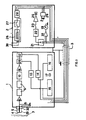
- the device consists of a part 1 housed in a separate housing and a second part 2, which is also housed in a separate housing and is connected to the first part 1 by a flexible, shielded cable 3, the first part the probe, filter stages, amplification and display and the second part contains the measuring circuit and power supply.
- the probe consists of an outer shield and a measuring electrode 5 made of electrically conductive material, which is insulated from the shield and from the housing.
- the measuring electrode 5 is embedded on one side in a wall opening, this wall 32 being fastened to the housing and being electrically insulated from it, and a metal covering 33 serving as a shield encasing the measuring electrode into the wall and the free end leaves the measuring electrode accessible to the electrostatic field through a window 4 that can be aligned parallel to the surface of the organism.
- the window 4 is, according to the invention, as shown in FIGS. 7 and 8, formed from polarizable liquid crystal inserted between two conductive layers.
- Non-conductive materials which have a higher dielectric constant than the air, can also be applied to the window 4 in order to increase the capacitance of the capacitor formed by the organism surface and by the free electrode end.
- the probe is held so close to the organism surface 7 that the charge on the measuring electrode 5 adapts in size to the charge on the surface 7, but with the opposite sign. This leads electrons to or away from the earth. Thus, a current flows through the compensation resistor 6. Since the resistance value is very high, a small current is sufficient to build up a voltage that can be picked up by an amplifier 8.
- the wall 32 is designed such that the measuring electrode 5 and the cladding 32 can be easily replaced and adapted to the given circumstances, such as, for. B. by means of screw plugs, bayonet fitting, clamping, etc.
- the measured signals have a frequency of 0 to 10 Hz; the higher frequencies are cut off by filter 9 at 36 dB / oct. Interfering electrical signals are thereby filtered out.
- high-pass filters 10 and 20 are attached.
- this filter property can be achieved by two differential circuits 10 and 20.
- the signal is first amplified by the amplifier 11 and separated into a positive and a negative signal for further processing. Both signals are amplified logarithmically, so that a weak signal is amplified by 50 dB more than a strong signal.
- the positive signal is amplified logarithmically in amplifier 13 and the negative signal in amplifier 14.
- Light-emitting diodes (L.e.d.) 15 and 16 display the signals discretely. The zero level is continuously indicated by an additional diode 17 for orientation.
- part 2 of the device contains an analog mA meter 19, the signal of which comes from a differential amplifier 18.
- Figure 3 gives the detailed circuit of these functions.
- acoustic signal which, by means of switch 21, reproduces either the positive signal, the negative signal or both signals.
- the acoustic reproduction 25 can be switched off by a switch 23.
- the acoustic signal makes the permanent monitoring of the display device unnecessary.
- this acoustic reproduction can be achieved by a converter 22, which converts voltages into frequencies, so that the frequency increases as soon as the Tension increases.
- a volume control can also be provided by a potentiometer 24.
- the second part of the device has an energy supply source, which is preferably provided with a 12 V battery charger 26 or a battery.
- the entire device can be energized by switch 27.
- a rectifier 28 can also be provided, which stabilizes the fluctuating battery voltages between 10 and 12 V.
- a charge control lamp 29 can also be installed.
- the probe At position 1 the probe is brought closer to the surface of the organism. As soon as the probe is close enough, preferably about 10 cm, a first current flows through the high-impedance resistor in order to achieve the automatic zeroing (position A in FIG. 6).
- the stop of the display device at pathological points can be clearly separated from the rest of the curve.
- the voltage diagram according to FIG. 6 clearly shows two zones between B and D on the one hand and C and E on the other in which measurable voltage differences. to rule.
- an abnormality is found, in which a pathological process takes place. This can be a recovery process, such as healing a wound or a pain center, e.g. B. act a tumor.
- the voltage curve between C and E indicates a concentrated, more active zone. This is a so-called acupuncture point.
- FIG. 6 which represents the recording of a measurement obtained with a device not falling under claim 1, leaves two. recognize important medical applications.
- the first application is the precise search for acupuncture points.
- the second application is to seek out a pathological process, such as. B. a pain center that is difficult to locate. It happens very often that a general sensation of pain does not allow a precise statement about the center of the pain and consequently for the doctor no determination of the cause of the pain or diagnosis. This fact is particularly valuable in animals or even plants that are unable to provide information about a pain center.
- the voltage diagram from FIG. 6 also shows at A and F that a movement perpendicular to the surface to be scanned triggers a measurement signal. From this one could conclude that in order to avoid interference signals the condition of the measurement process is that the probe is parallel to the measurement surfaces, i.e. while maintaining a constant distance.
- Figure 6 shows, however, that the amplitudes of signals A and F are significantly smaller than those of signals B-D and C-E, i.e. that a deviation from the optimal tactile movement triggers an interference signal, but that the superimposition of such an interference signal due to its low amplitude with a measurement signal A-D or C-E has no disruptive influence on the latter, i.e. on the basis of their amplitudes, it is very easy to distinguish the measurement signals from the interference signals.
- the dielectric constant of the window 4 consisting of liquid crystals is modulated.
- This material has the peculiarity of having a different dielectric constant with different polarization.
- the probe therefore consists of the measuring electrode 5, the shield 33 and the window 4, which consists of liquid crystals which are polarized by a modulation voltage on the electrically conductive layers 50 and 51, the conductive layers being electrically insulated from the shield .
- FIG. 8 shows a preferred, very compact embodiment in which the measuring electrode 5 is attached to the liquid crystal window 4 in an insulated manner.
- the measured signal can be amplified synchronously with a reference signal.
- This reference signal can, for. B. from an oscillator that simultaneously stimulates the field modulation.
Landscapes
- Life Sciences & Earth Sciences (AREA)
- Health & Medical Sciences (AREA)
- Medical Informatics (AREA)
- Biophysics (AREA)
- Pathology (AREA)
- Engineering & Computer Science (AREA)
- Biomedical Technology (AREA)
- Heart & Thoracic Surgery (AREA)
- Physics & Mathematics (AREA)
- Molecular Biology (AREA)
- Surgery (AREA)
- Animal Behavior & Ethology (AREA)
- General Health & Medical Sciences (AREA)
- Public Health (AREA)
- Veterinary Medicine (AREA)
- Investigating Or Analyzing Materials By The Use Of Electric Means (AREA)
- Measurement And Recording Of Electrical Phenomena And Electrical Characteristics Of The Living Body (AREA)
Description
- Die Erfindung betrifft eine Vorrichtung für das kontaktlose Messen von Ladungskonzentrationen und Potentialunterschieden bei biologischen Organismen, insbesondere bei Menschen, Tieren und Pflanzen.
- Es ist bekannt, dass unter gewissen Bedingungen elektrische Ladungskonzentrationen und Potentialunterschiede in Organismen bestehen und entstehen. Pathologische Prozesse, Genesungsprozesse und Informationsprozesse verlaufen nach einem elektrischen Gleichstromsystem in dem elektrische Ladungskonzentrationen und Potentialunterschiede zum Steuern der Genesungsprozesse und der Genesung selbst auftreten. Bei Pflanzen, Bäumen und Sträuchern ist es bekannt, dass die von der Sonne beschienenen Teile ein höheres elektrisches Potential aufweisen als die im Schatten befindlichen Teile.
- Diese elektrischen Potentialunterschiede geben über die Lebensprozesse im Bioorganismus Auskunft. Weitere Einzelheiten ergeben sich aus " The basic biological data transmission and control system influenced by electrical forces" von R.O. Becker in "Annals of the New York Academy of Sciences", vol. 238, 11-10-1974, S. 236 - 241.
- Um diese Potentialunterschiede zu messen kann man Geräte benützen, die elektrische Felder und ihre Grösse ausfindig machen. Es gibt mehrere dieser Geräte, die aber alle an der Bauart der Messonde scheitern und den Nachteil aufweisen, unpräzise zu sein.
- Aus dem Artikel aus IEEE " Transactions on biomedical engineering (US)" Band BME-27, Nr 12, Dezember 1980, New York (US), B.C. Towe: "An air ionization biopotential electrode" Seiten 733-736 sind Messelektroden bekannt, die dazu dienen Oberflächenspannungsunterschiede kontaktlos zu messen. Die Anwendung solcher Elektroden fordert jedoch die Ionisation der zwischen der Organismusoberfläche und der Elektrode befindlichen Luft, um somit ein elektrisch leitendes Medium zu bilden. In diesem besonderen Fall wird die Ionisation durch eine auf der Elektrode befindliche ionisierende Strahlenquelle erreicht, insbesondere ein 100 u. Ci-radioaktives Polonium -210- Radioisotop, das X-Strahlen aussendet.
- Aus der DE-A-2 928 828 sind eine Vorrichtung gemäß dem Obergriff des Anspruchs 1 sowie ein Verfahren zum kontaktlosen Messen von Ladungskonzentrationen und Potentialunterschieden bei biologischen Organismen bekannt. Gemäss diesem Verfahren wird eine Messelelektrode kontaktlos über die Organismusoberfläche gehalten, wobie das System Messelektrode/Organismusoberfläche einen Kondensator bildet. Es wird in dem Kondensator eine fortdauernde Änderung des elektrischen Feldes hervorgerufen und die dadurch entstehenden Ladungsverschiebungen werden gemessen und ausgewertet.
- Das Ziel der Erfindung besteht darin eine Vorrichtung zu schaffen, die das kontaktlose Messen von Ladungskonzentrationen und elektrischen Potentialunterschieden bei Bio-Organismen ermöglicht. Diese neue Vorrichtung soll präzise arbeiten und weist dementsprechend neuartige Sonden auf.
- Die Lösung der gestellten Aufgabe beruht auf einem bekannten Verfahren, bei dem in einem durch eine kontaktlos über die Organismusoberfläche gehaltene Messelelektrode und die Organismusoberfläche an sich gebildeten Kondensator eine fortdauernde Änderung des elektrostatischen Feldes hervorgerufen wird und die daraus resultierenden Ladungsverschiebungen gemessen und ausgewertet werden, die ein Ausdruck der im Bio-Organismus bestehenden Ladungskonzentrationen sind.
- Gemäs diesem Messverfahren bildet die Sonde einen Kondensator mit der Oberfläche des Organismus. Beim Anschluss dieses Kondensators an eine äussere Schaltung fliesst ein elektrischer Strom, der die Ladung der Messelelektrode an diejenige der Organismusoberfläche anpasst. Eine Veränderung des elektrostatischen Feldes im Kondensator verursacht folglich eine entsprechende Veränderung der Ladung an der Messelektrode. Durch eine solche Veränderung fliesst also ein Strom durch die äussere Schaltung. Dieser Strom ist ein Mass für die Ladungsänderung und also auch den Potentialunterschied im Organismus.
- Um dieses Verfahren anwenden zu können, wird, nach der vorliegenden Erfindung, eine Vorrichtung gemäss Patentanspruch 1 geschaffen.
- Die oben genannten Schaltungen bestehen aus einer Ausgleichschaltung mit hochohmigem Widerstand, die dafür sorgt, dass die Ladungen an den beiden Kondensatorteilen immer entgegengesetzt bleiben und somit ein Ladungsverschub gemessen wird, sowie aus Filterstufen, Verstärkerstufen und Schaltungen zum Auswerten und Anzeigen der gemessene Werte.
- Da die gemessenen Werte klein sind, ist auf eine besonders gute Abschirmung aller Bestandteile zu achten, um den äusseren Einfluss auf die sensible Vorrichtung so gering wie möglich zu halten. Deshalb muss die Elektrode besonders gut abgeschirmt werden, ebenso wie die Verbindungskabel und die Gehäuse. Das in der Abschirmung der Elektrode vorgesehene Fenster, durch das das elektrostatische Feld an die leitende Messelektrode heran kann wird zweckmässigerweise parallel zur Organismusoberfläche ausgerichtet.
- Bevorzugte Ausführungsformen der Vorrichtung nach der Erfindung werden anhand der nachstehenden Zeichnungen näher erläutert:
- Figur 1 zeigt eine schematische Anordnung der verschiedenen Bestandteile;
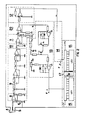
- Figur 2 zeigt eine Ausführungsform des ersten Teils der Vorrichtung, die in Figur 1 schematisch dargestellt ist;
- Figur 3 zeigt den zweiten Teil der in Figur 1 schematisch dargestellten Vorrichtung;
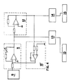
- Figur 4 zeigt eine andere Ausführungsform des ersten Teils der in Figur 1 schematisch dargestellten Vorrichtung;
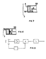
- Figur 5 zeigt eine Anwendung der erfindungsgemässen Vorrichtung bei einem menschlichen Körperteil;
- Figur 6 zeigt den Verlauf einer Kurve, die auf der Anzeige einer nicht gemäß Anspruch 1 ausgebildeten - jedoch ähnlichen - Vorrichtung erhalten wurde:
- Figur 7 zeigt eine schematisch dargestellte Ausführungsform mit modulierbarer dielektrischer Konstante;
- Figur 8 zeigt eine weitere Ausführungsform mit modulierbarer dielektrischer Konstante;
- Figur 9 zeigt ein Blockschaltbild das zu den Ausführungsformen gemäss den Figuren 7 oder 8 passt.
- In den Figuren stehen gleiche Bezugszahlen für gleiche oder ähnliche Bauteile.
- Gemäss Figur 1 besteht die Vorrichtung aus einem in einem getrennten Gehäuse untergebrachten Teil 1 und aus einem zweiten Teil 2, der ebenfalls in einem getrennten Gehäuse untergebracht ist und mit dem ersten Teil 1 durch ein flexibles, abgeschirmtes Kabel 3 verbunden ist, wobei der erste Teil die Sonde, Filterstufen, Verstärkung und Anzeige umfasst und der zweite Teil die Messchaltung und Energieversorgung enthält.
- Anstatt die beiden Teile 1 und 2 in separaten Gehäusen unterzubringen ist es auch möglich die beiden Teile in einem Gehäuse zu vereinigen.
- Nach der in den Figuren 1 und 2 dargestellten Ausführungsform besteht die Sonde aus einer äusseren Abschirmung und einer Messelektrode 5 aus elektrisch leitendem Material, die von der Abschirmung und vom Gehäuse isoliert ist.
- Gemäss einer Ausführungsform ist die Messelektrode 5 an einer Seite in einer Wandungsöffnung eingelassen, wobei diese Wandung 32 am Gehäuse befestigt ist und von ihm elektrisch isoliert ist und wobei eine metallische Verkleidung 33 als Abschirmung dienend die Messelektrode bis in die Wandung hinein umhüllt und das freie Ende der Messelektrode durch ein Fenster 4, das parallel zur Organismusoberfläche ausrichtbar ist, dem elektrostatischen Feld zugänglich lässt. Das Fenster 4 wird erfindungsgemäß, wie in den Figuren 7 und 8 dargestellt ist, aus zwischen zwei leitenden Schichten eingefügtes polarisierbares Flüssigkristall gebildet.
- Es können ebenfalls nicht leitende Materialien, die eine höhere dielektrische Konstante besitzen als die Luft, auf dem Fenster 4 angebracht werden, um die Kapazität des durch die Organismusoberfläche und durch das freie Elektrodenende gebildeten Kondensators zu erhöhen.
- Die Sonde wird so nahe an der Organismusoberfläche 7 gehalten, dass die Ladung an der Messelektrode 5 sich der Ladung auf der Oberfläche 7 in der Grösse anpasst, aber von entgegengesetztem Zeichen. Dadurch werden Elektronen heran oder zur Erde weggeleitet. So fliesst also ein Strom durch den Ausgleichwiderstand 6. Da der Widerstandswert sehr hoch ist, genügt ein geringer Strom um eine Spannung aufzubauen, die von einem Verstärker 8 aufgenommen werden kann.
- Die Wandung 32 ist so ausgebildet, dass Messelektrode 5 und Verkleidung 32 leicht ausgewechselt und den gegebenen Umständen angepasst werden können, wie z. B. mittels Schraubstopfen, Bajonettfassung, Klemmung, usw.
- Die gemessenen Signale haben eine Frequenz von 0 bis 10 Hz; die höheren Frequenzen werden durch Filter 9 mit 36 dB/Okt abgeschnitten. Dadurch werden störende elektrische Signale ausgefiltert.
- Um den Messausschlag der Vorrichtung unabhängig von in den Verstärkerstufen hervorgerufenen Offsetspannungen zu halten, werden Hochdurchlassfilter 10 und 20 angebracht.
- Nach Figur 2 kann diese Filtereigenschaft durch zwei Differentialschaltungen 10 und 20 erreicht werden.
- Gemäss Figur 4 kann das gleiche Resultat mit einer Integrationsschaltung in Gegenkopplung 10' erreicht werden, wobei jedoch im Gesamten weniger Bauelemente benutzt werden.
- Das Signal wird durch den Verstärker 11 zuerst verstärkt und zur weiteren Verarbeitung in ein positives und ein negatives Signal getrennt. Beide Signale werden logarithmisch verstärkt, sodass ein schwaches Signal um 50 dB mehr verstärkt wird als ein starkes Signal. Das positive Signal wird im Verstärker 13 logarithmisch verstärkt und das negative Signal im Verstärker 14. Leuchtdioden (L.e.d.) 15 und 16 zeigen die Signale diskret an. Der Nullstand wird laufend durch eine zusätzliche Diode 17 zur Orientierung angegeben.
- Gemäss der unter Bezug auf die Figuren 1, 7 und 8 erläuterten Ausführungsform der Erfindung enthält Teil 2 der Vorrichtung ein analoges mA-Meter 19, dessen Signal von einem Differentialverstärker 18 kommt. Figur 3 gibt die Detailschaltung dieser Funktionen.
- Man kann zusätzlich auch ein akustisches Signal hervorrufen, das mittels Schalter 21 entweder das positive Signal, das negative Signal oder beide Signale wiedergibt. Die akustische Wiedergabe 25 kann durch einen Schalter 23 abgeschaltet werden. Das akustische Signal erübrigt die permanente Überwachung der Anzeigevorrichtung.
- Nach Figur 3 kann diese akustische Wiedergabe durch einen Umwandler 22 erreicht werden, der Spannungen in Frequenzen umsetzt, sodass die Frequenz ansteigt sobald die Spannung zunimmt. Man kann ebenfalls eine Lautstärkeregelung durch ein Potentiometer 24 vorsehen.
- Der zweite Teil der Vorrichtung weist eine Energieversorgungsquelle, auf die vorzugsweise aus einem 12 V-Akkulader 26 beseht oder aus einer Batterie. Durch Schalter 27 kann die gesamte Vorrichtung unter Spannung gesetzt werden. Man kann auch einen Gleichrichter 28 vorsehen, der die schwankenden Batteriespannungen zwischen 10 und 12 V stabilisiert.
- Eine Ladekontroll-Leuchte 29 kann ebenfalls eingebaut werden.
- Anhand der Figuren 5 und 6 wird nun eine Anwendung der erfindungsgemässen Vorrichtung bei der Abtastung eines Vorderarmes erklärt.
- Bei Position 1 wird die Sonde der Organismusoberfläche genähert. Sobald die Sonde nahe genug ist, vorzugsweise etwa 10 cm, fliesst ein erster Strom durch den hochohmigen Widerstand um die automatische Nulleinstellung zu erreichen (Position A in Figur 6).
- Bei Position 11 wird die Band auf Abstand abgetastet. Sobald man sich einem Punkt nähert, in dem ein pathologischer Prozess abläuft, kann ein typischer Spannungsverlauf B-D oder C-E festgestellt werden.
- In Position 111 wird die Sonde zurückgezogen und die Anzeigevorrichtung schlägt in entgegengesetztem Sinn im Vergleich zu A aus, da die Kapazität des Kondensators durch die immer grösser werdende Distanz verändert wird.
- Der Anschlag der Anzeigevorrichtung bei pathologischen Punkten ist deutlich vom restlichen Kurvenverlauf trennbar.
- Das Spannungsdiagramm gemäss Figur 6 lässt zwischen B und D einerseits und C und E andererseits deutlich zwei Zonen erkennen in welchen messbare Spannungsunterschiede. herrschen. In der breiteren Zone zwischen B und D wird eine Anomalie festgestellt, in welcher sich ein pathologischer Prozess abwickelt. Dabei kann es sich um einen Genesungsprozess, wie zum Beispiel das Heilen einer Wunde oder ein Schmerzzentrum, z. B. ein Tumor handeln.
- Der Spannungsverlauf zwischen C und E deutet auf eine konzentrierte aktivere Zone hin. Hier handelt es sich um einen sogenannten Akupunkturpunkt.
- Das Spannungsdiagramm der Figur 6 welches die Aufzeichnung einer Messung darstellt die mit einer nicht unter Anspruch 1 fallenden Vorrichtung erhalten wurde, lässt gleich zwei. wichtige medizinische Anwendungsmöglichkeiten erkennen.
- Die erste Anwendung ist, wie es die Kurve zwischen C und D verdeutlicht, das präzise Aufsuchen von Akupunkturpunkten.
- Die zweite Anwendungsmöglichkeit ist das Aufsuchen eines pathologischen Prozesses, wie z. B. eines schwer lokalisierbaren Schmerzzentrums. Es kommt nämlich sehr oft vor, dass eine allgemeine Schmerzempfindung keine präzise Aussage über das Zentrum des Schmerzes und folglich für den Arzt keine Feststellung der Ursache des Schmerzen bzw. Diagnostik zulässt. Diese Tatsache gewinnt besonders an Wert bei Tieren oder sogar Pflanzen welche nicht in der Lage sind, eine Auskunft betreffend ein Schmerzzentrum zu geben.
- Das Spannungsdiagramm aus Figur 6 lässt ebenfalls bei A und F erkennen, dass eine Bewegung senkrecht zur abzutastenden Oberfläche ein Messignal auslöst. Daraus könnte man schliessen, dass zur Vermeidung von Störsignalen dem Messverfahren die Bedingung vorausgesetzt ist, dass die Sonde parallel zu den Messoberflächen, d.h. unter Beibehalten eines konstanten Abstandes, geführt werden muss. Figur 6 zeigt jedoch, dass die Amplituden der Signale A und F wesentlich kleiner sind als diejenigen der Signal B-D und C-E, d.h. dass eine Abweichung von der optimalen Tastbewegung zwar ein Störsignal auslöst, aber dass die Überlagerung eines solchen Störsignals wegen seiner geringen Amplitude, mit einem Messignal A-D oder C-E keinen störenden Einfluss auf letztere hat, d.h. auf Grund ihrer Amplituden kann man sehr leicht die Messignale von den Störsignalen unterscheiden.
- Ein wesentliches Merkmal des anhand der Figuren 5 und 6 erläuterten Verfahrens, das unter Verwendung der in den Figuren 1 bis 4 und 7, 8 beschriebenen Vorrichtung durchgeführt werden kann, besteht darin, dass keine Absolutwerte, sondern Potential- oder Ladungsgradienten gemessen werden. Dadurch werden störend wirkende Faktoren, wie z. B. statische Elektrizität auf der Messoberfläche, Kleidung, Bandagen, Tierfell, usw. automatisch eliminiert.
- Nach der vorliegenden Erfindung wird die dielektrische Konstante des aus Flüssigkristallen bestehenden Fensters 4 moduliert. Dieses Material weist die Besonderheit auf, bei verschiedener Polarisation eine verschiedene dielektrische Konstante zu besitzen. Nach Figur 7 besteht demnach die Sonde aus der Messelektrode 5, der Abschirmung 33 und dem Fenster 4, das aus Flüssigkristallen besteht, die durch eine Modulationsspannung an den elektrisch leitenden Schichten 50 und 51 polarisiert werden, wobei die leitenden Schichten von der Abschirmung elektrisch isoliert sind.
- Figur 8 zeigt eine bevorzugte, sehr kompakte Ausführungsform, in der die Messelektrode 5 isoliert auf dem Flüssigkristallfenster 4 befestigt ist.
- Nach dem Blockschaltbild der Figur 9 kann das gemessene Signal synchron mit einem Referenzsignal verstärkt werden. Dieses Referenzsignal kann, z. B. von einem Oszillator, der gleichzeitig die Feldmodulation anregt stammen.
Claims (2)
Priority Applications (1)
| Application Number | Priority Date | Filing Date | Title |
|---|---|---|---|
| AT83105771T ATE31869T1 (de) | 1982-07-01 | 1983-06-13 | Verfahren und vorrichtung fuer das kontaktlose messen von ladungskonzentrationen und potentialunterschieden bei biologischen organismen. |
Applications Claiming Priority (2)
| Application Number | Priority Date | Filing Date | Title |
|---|---|---|---|
| LU84250A LU84250A1 (de) | 1982-07-01 | 1982-07-01 | Verfahren und vorrichtung fuer das kontaktlose messen von spannungsunterschieden bei lebenden organismen |
| LU84250 | 1982-07-01 |
Publications (2)
| Publication Number | Publication Date |
|---|---|
| EP0098413A1 EP0098413A1 (de) | 1984-01-18 |
| EP0098413B1 true EP0098413B1 (de) | 1988-01-13 |
Family
ID=19729914
Family Applications (1)
| Application Number | Title | Priority Date | Filing Date |
|---|---|---|---|
| EP83105771A Expired EP0098413B1 (de) | 1982-07-01 | 1983-06-13 | Verfahren und Vorrichtung für das kontaktlose Messen von Ladungskonzentrationen und Potentialunterschieden bei biologischen Organismen |
Country Status (5)
| Country | Link |
|---|---|
| US (1) | US4602639A (de) |
| EP (1) | EP0098413B1 (de) |
| AT (1) | ATE31869T1 (de) |
| DE (1) | DE3375279D1 (de) |
| LU (1) | LU84250A1 (de) |
Families Citing this family (68)
| Publication number | Priority date | Publication date | Assignee | Title |
|---|---|---|---|---|
| CN1012257B (zh) * | 1986-09-09 | 1991-04-03 | 顾涵森 | 生物电信号检测装置 |
| US4864282A (en) * | 1986-10-21 | 1989-09-05 | Sasson Toeg | Method and apparatus for detecting or measuring the presence of humans or biological organism |
| US4955383A (en) * | 1988-12-22 | 1990-09-11 | Biofield Corporation | Discriminant function analysis method and apparatus for disease diagnosis and screening |
| US5458142A (en) * | 1993-03-19 | 1995-10-17 | Farmer; Edward J. | Device for monitoring a magnetic field emanating from an organism |
| JPH0838437A (ja) * | 1994-05-25 | 1996-02-13 | Hiroshi Motoyama | 生体表面電位測定装置および診断装置 |
| ATE499660T1 (de) | 1998-09-11 | 2011-03-15 | Gr Intellectual Reserve Llc | Verfahren und system für biometrische erkennung basiert auf elektrischen und/oder magnetischen eigenschaften |
| US6507662B1 (en) | 1998-09-11 | 2003-01-14 | Quid Technologies Llc | Method and system for biometric recognition based on electric and/or magnetic properties |
| US6343140B1 (en) | 1998-09-11 | 2002-01-29 | Quid Technologies Llc | Method and apparatus for shooting using biometric recognition |
| US6807438B1 (en) * | 1999-08-26 | 2004-10-19 | Riccardo Brun Del Re | Electric field sensor |
| AU6678500A (en) * | 1999-08-26 | 2001-03-26 | Cordless Antistatic Research Inc. | Electric field sensor |
| US20030036691A1 (en) * | 2000-08-10 | 2003-02-20 | Stanaland Thomas G. | Capacitively coupled electrode system with variable capacitance for sensing potentials at the surface of tissue |
| US20020038092A1 (en) * | 2000-08-10 | 2002-03-28 | Stanaland Thomas G. | Capacitively coupled electrode system for sensing voltage potentials at the surface of tissue |
| US7088175B2 (en) * | 2001-02-13 | 2006-08-08 | Quantum Applied Science & Research, Inc. | Low noise, electric field sensor |
| GB0129390D0 (en) * | 2001-12-07 | 2002-01-30 | Clark Terrence D | Electrodynamic sensors and applications thereof |
| US8923956B2 (en) | 2001-12-07 | 2014-12-30 | The University Of Sussex | Electrodynamic sensors and applications thereof |
| US7169107B2 (en) * | 2002-01-25 | 2007-01-30 | Karen Jersey-Willuhn | Conductivity reconstruction based on inverse finite element measurements in a tissue monitoring system |
| US20040158166A1 (en) * | 2003-02-10 | 2004-08-12 | Levengood William C. | Method and apparatus for detecting, recording and analyzing spontaneously generated transient electric charge pulses in living organisms |
| US20040204658A1 (en) * | 2003-04-10 | 2004-10-14 | Dietz Phillip W. | Systems and methods for providing an enhanced bioelectric sensing surface |
| US6961601B2 (en) * | 2003-06-11 | 2005-11-01 | Quantum Applied Science & Research, Inc. | Sensor system for measuring biopotentials |
| AU2004293750B2 (en) * | 2003-10-07 | 2009-07-23 | Quasar Federal Systems, Inc. | Integrated sensor system for measuring electric and/or magnetic field vector components |
| AU2005206735A1 (en) * | 2004-01-08 | 2005-08-04 | Richard Nuccitelli | Application of the Kelvin probe techinique to mammalian skin and other epithelial structures |
| US7173437B2 (en) * | 2004-06-10 | 2007-02-06 | Quantum Applied Science And Research, Inc. | Garment incorporating embedded physiological sensors |
| US7245956B2 (en) * | 2004-07-15 | 2007-07-17 | Quantum Applied Science & Research, Inc. | Unobtrusive measurement system for bioelectric signals |
| US20060041196A1 (en) * | 2004-08-17 | 2006-02-23 | Quasar, Inc. | Unobtrusive measurement system for bioelectric signals |
| US7684854B2 (en) * | 2004-08-31 | 2010-03-23 | Seoul National University Industry Foundation | Apparatus and method for measuring electric non-contact electrocardiogram in everyday life |
| US8694088B2 (en) * | 2005-01-07 | 2014-04-08 | Bioelectromed Corp. | Hand-held electric field imager for measuring the electric field in mammalian skin and other epithelial structures |
| US8597187B2 (en) * | 2005-01-07 | 2013-12-03 | Bioelectromed Corp. | Hand-held electric field imager for measuring the surface topography of mammalian skin and other epithelial structures |
| US8295903B2 (en) * | 2008-05-25 | 2012-10-23 | Auraprobe, Inc. | Electron avalanche putative energy field analyzer |
| US20140198034A1 (en) | 2013-01-14 | 2014-07-17 | Thalmic Labs Inc. | Muscle interface device and method for interacting with content displayed on wearable head mounted displays |
| KR102330889B1 (ko) | 2013-02-22 | 2021-11-26 | 페이스북 테크놀로지스, 엘엘씨 | 제스처-기반 제어를 위해 근활성도 센서 신호와 관성 센서 신호를 결합하는 방법 및 기기 |
| WO2014186370A1 (en) | 2013-05-13 | 2014-11-20 | Thalmic Labs Inc. | Systems, articles and methods for wearable electronic devices that accommodate different user forms |
| US9445740B1 (en) * | 2013-06-28 | 2016-09-20 | West Affum Holdings Corp. | Patient signal sensing device |
| US11426123B2 (en) | 2013-08-16 | 2022-08-30 | Meta Platforms Technologies, Llc | Systems, articles and methods for signal routing in wearable electronic devices that detect muscle activity of a user using a set of discrete and separately enclosed pod structures |
| US12504816B2 (en) | 2013-08-16 | 2025-12-23 | Meta Platforms Technologies, Llc | Wearable devices and associated band structures for sensing neuromuscular signals using sensor pairs in respective pods with communicative pathways to a common processor |
| US11921471B2 (en) | 2013-08-16 | 2024-03-05 | Meta Platforms Technologies, Llc | Systems, articles, and methods for wearable devices having secondary power sources in links of a band for providing secondary power in addition to a primary power source |
| US20150124566A1 (en) | 2013-10-04 | 2015-05-07 | Thalmic Labs Inc. | Systems, articles and methods for wearable electronic devices employing contact sensors |
| US10042422B2 (en) | 2013-11-12 | 2018-08-07 | Thalmic Labs Inc. | Systems, articles, and methods for capacitive electromyography sensors |
| US9788789B2 (en) | 2013-08-30 | 2017-10-17 | Thalmic Labs Inc. | Systems, articles, and methods for stretchable printed circuit boards |
| US9372535B2 (en) | 2013-09-06 | 2016-06-21 | Thalmic Labs Inc. | Systems, articles, and methods for electromyography-based human-electronics interfaces |
| US9483123B2 (en) | 2013-09-23 | 2016-11-01 | Thalmic Labs Inc. | Systems, articles, and methods for gesture identification in wearable electromyography devices |
| WO2015081113A1 (en) | 2013-11-27 | 2015-06-04 | Cezar Morun | Systems, articles, and methods for electromyography sensors |
| CA2939644A1 (en) | 2014-02-14 | 2015-08-20 | North Inc. | Systems, articles, and methods for elastic electrical cables and wearable electronic devices employing same |
| US10199008B2 (en) | 2014-03-27 | 2019-02-05 | North Inc. | Systems, devices, and methods for wearable electronic devices as state machines |
| US9880632B2 (en) | 2014-06-19 | 2018-01-30 | Thalmic Labs Inc. | Systems, devices, and methods for gesture identification |
| US9807221B2 (en) | 2014-11-28 | 2017-10-31 | Thalmic Labs Inc. | Systems, devices, and methods effected in response to establishing and/or terminating a physical communications link |
| JP6721607B2 (ja) | 2015-01-10 | 2020-07-15 | デュレン、デボラ | 患者の治療と転帰の診断と検証のための、自律神経機能の測定方法および装置 |
| US10078435B2 (en) | 2015-04-24 | 2018-09-18 | Thalmic Labs Inc. | Systems, methods, and computer program products for interacting with electronically displayed presentation materials |
| US10602957B2 (en) | 2015-06-30 | 2020-03-31 | Varuna Biomedical Corporation | Systems and methods for detecting and visualizing biofields with nuclear magnetic resonance imaging and QED quantum coherent fluid immersion |
| US11216069B2 (en) | 2018-05-08 | 2022-01-04 | Facebook Technologies, Llc | Systems and methods for improved speech recognition using neuromuscular information |
| US12554325B2 (en) | 2016-07-25 | 2026-02-17 | Meta Platforms Technologies, Llc | Methods and apparatuses for low latency body state prediction based on neuromuscular data |
| US20200073483A1 (en) | 2018-08-31 | 2020-03-05 | Ctrl-Labs Corporation | Camera-guided interpretation of neuromuscular signals |
| WO2018022602A1 (en) | 2016-07-25 | 2018-02-01 | Ctrl-Labs Corporation | Methods and apparatus for predicting musculo-skeletal position information using wearable autonomous sensors |
| EP3697297A4 (de) | 2017-10-19 | 2020-12-16 | Facebook Technologies, Inc. | Systeme und verfahren zur identifizierung biologischer strukturen in zusammenhang mit signalen neuromuskulären ursprungs |
| US11493993B2 (en) | 2019-09-04 | 2022-11-08 | Meta Platforms Technologies, Llc | Systems, methods, and interfaces for performing inputs based on neuromuscular control |
| US11481030B2 (en) | 2019-03-29 | 2022-10-25 | Meta Platforms Technologies, Llc | Methods and apparatus for gesture detection and classification |
| US11961494B1 (en) | 2019-03-29 | 2024-04-16 | Meta Platforms Technologies, Llc | Electromagnetic interference reduction in extended reality environments |
| US12579768B2 (en) | 2018-01-25 | 2026-03-17 | Meta Platforms Technologies, Llc | Wearable electronic devices, extended reality systems including neuromuscular sensors, and methods for generating text from speech input and modifying the generated text based on neuromuscular data |
| US11907423B2 (en) | 2019-11-25 | 2024-02-20 | Meta Platforms Technologies, Llc | Systems and methods for contextualized interactions with an environment |
| US11150730B1 (en) | 2019-04-30 | 2021-10-19 | Facebook Technologies, Llc | Devices, systems, and methods for controlling computing devices via neuromuscular signals of users |
| US10937414B2 (en) | 2018-05-08 | 2021-03-02 | Facebook Technologies, Llc | Systems and methods for text input using neuromuscular information |
| US10592001B2 (en) | 2018-05-08 | 2020-03-17 | Facebook Technologies, Llc | Systems and methods for improved speech recognition using neuromuscular information |
| CN112789577B (zh) | 2018-09-20 | 2024-04-05 | 元平台技术有限公司 | 增强现实系统中的神经肌肉文本输入、书写和绘图 |
| CN113423341B (zh) | 2018-11-27 | 2024-12-03 | 元平台技术有限公司 | 用于可穿戴电极传感器系统的自动校准的方法和装置 |
| US11868531B1 (en) | 2021-04-08 | 2024-01-09 | Meta Platforms Technologies, Llc | Wearable device providing for thumb-to-finger-based input gestures detected based on neuromuscular signals, and systems and methods of use thereof |
| US12340627B2 (en) | 2022-09-26 | 2025-06-24 | Pison Technology, Inc. | System and methods for gesture inference using computer vision |
| US12366923B2 (en) | 2022-09-26 | 2025-07-22 | Pison Technology, Inc. | Systems and methods for gesture inference using ML model selection |
| US12366920B2 (en) | 2022-09-26 | 2025-07-22 | Pison Technology, Inc. | Systems and methods for gesture inference using transformations |
| US12502110B2 (en) | 2023-10-24 | 2025-12-23 | Pison Technology, Inc. | Systems and methods for determining physiological state based on surface biopotentials |
Family Cites Families (15)
| Publication number | Priority date | Publication date | Assignee | Title |
|---|---|---|---|---|
| US31097A (en) * | 1861-01-08 | Meat-cutter | ||
| CH352781A (de) * | 1955-06-02 | 1961-03-15 | Ludwig Dr Machts | Verfahren und Vorrichtung zur Feststellung von Eigenschaften und Verschiedenheiten von Körpern, insbesondere im organischen Aufbau des menschlichen oder tierischen Körpers sowie von zeitlichen Veränderungen desselben |
| US3323515A (en) * | 1964-05-05 | 1967-06-06 | Foner Max | Apparatus for indicating potentials of living tissue |
| DE1281573B (de) * | 1964-12-08 | 1968-10-31 | Kalle Ag | Messsonde zur Bestimmung der oertlichen Ladungsverteilung auf Oberflaechen von Festkoerpern |
| US3611127A (en) * | 1968-09-16 | 1971-10-05 | Robert E Vosteen | Electrostatic potential and field measurement apparatus having a capacitor detector with feedback to drive the capacitor detector to the potential being measured |
| US3744482A (en) * | 1971-06-29 | 1973-07-10 | Hittman Ass Inc | Dry contact electrode with amplifier for physiological signals |
| US3774108A (en) * | 1971-12-13 | 1973-11-20 | Frl Inc | Electrostatic potential detector |
| DE2520033A1 (de) * | 1975-05-06 | 1976-11-18 | Karlheinz Dr Med Helmbold | Hilfsmittel zur messung und zur gezielten beeinflussung des elektrischen potentials des menschen sowie zum optimalen schutz des physiologischen menschlichen potentials gegen aeussere stoerende einfluesse |
| DE2548354C2 (de) * | 1975-10-29 | 1984-10-11 | Messerschmitt-Bölkow-Blohm GmbH, 8000 München | Gerät für Lichttherapie mit einer Laserlichtquelle |
| USRE31097E (en) | 1977-07-21 | 1982-12-07 | Cardiokinetics, Inc. | Apparatus and method for detecton of body tissue movement |
| US4205267A (en) * | 1977-11-03 | 1980-05-27 | Williams Bruce T | High speed electrostatic voltmeter |
| US4200104A (en) * | 1977-11-17 | 1980-04-29 | Valleylab, Inc. | Contact area measurement apparatus for use in electrosurgery |
| DE2928826A1 (de) * | 1979-07-17 | 1981-02-12 | Wolfgang Pape | Verfahren und vorrichtung zur ermittlung von akupunkturstellen |
| US4303073A (en) * | 1980-01-17 | 1981-12-01 | Medical Plastics, Inc. | Electrosurgery safety monitor |
| US4387714A (en) * | 1981-05-13 | 1983-06-14 | Purdue Research Foundation | Electrosurgical dispersive electrode |
-
1982
- 1982-07-01 LU LU84250A patent/LU84250A1/de unknown
-
1983
- 1983-06-13 AT AT83105771T patent/ATE31869T1/de not_active IP Right Cessation
- 1983-06-13 DE DE8383105771T patent/DE3375279D1/de not_active Expired
- 1983-06-13 EP EP83105771A patent/EP0098413B1/de not_active Expired
- 1983-06-30 US US06/509,651 patent/US4602639A/en not_active Expired - Lifetime
Non-Patent Citations (1)
| Title |
|---|
| XEROX DISCLOSURE JOURNAL, Band 2, Nr. 6, November/Dezember 1977, STAMFORD/CONN. (US), R. CASE: "Liquid Cristal Electrometer", Seite 91 * |
Also Published As
| Publication number | Publication date |
|---|---|
| ATE31869T1 (de) | 1988-01-15 |
| EP0098413A1 (de) | 1984-01-18 |
| DE3375279D1 (en) | 1988-02-18 |
| LU84250A1 (de) | 1984-03-22 |
| US4602639A (en) | 1986-07-29 |
Similar Documents
| Publication | Publication Date | Title |
|---|---|---|
| EP0098413B1 (de) | Verfahren und Vorrichtung für das kontaktlose Messen von Ladungskonzentrationen und Potentialunterschieden bei biologischen Organismen | |
| DE68925454T2 (de) | Überprüfungs- und Überwachungsinstrument | |
| EP0273958B1 (de) | Vorrichtung zum feststellen von eigenschaften, verschiedenheiten und veränderungen des menschlichen oder tierischen körpers | |
| DE2906208C2 (de) | Einrichtung zum transkutanen Messen des Partialdrucks des Sauerstoffs im Blut | |
| DE3784177T2 (de) | Vorrichtung fuer die erfassung von gegenstaenden hinter einer oberflaeche. | |
| EP0890117A1 (de) | Vorrichtung und verfahren zur positionsbestimmung | |
| DE3910297A1 (de) | Beruehrungslos arbeitendes wegmesssystem | |
| DE2314336A1 (de) | Katheter zum messen der blutdurchlaufgeschwindigkeit und dgl | |
| DE68911758T2 (de) | Die Eigenschaften eines Flüssigkristalles nutzender Berührungsschalter. | |
| DE2500051A1 (de) | Messgeraet fuer die elektrische feldstaerke von wechselfeldern | |
| DE68909225T2 (de) | Messung der elektrischen impedanz von proben niedriger leitfähigkeit. | |
| DE3784661T2 (de) | Fluessigkristall-spannungsmessgeraet. | |
| CH652508A5 (en) | Direct-current resistance measuring and indicating device and use thereof | |
| DE3632591A1 (de) | Verfahren und vorrichtung zur messung oder ueberwachung einer physikalischen eigenschaft eines fluessigen gegenstandes | |
| EP0298441B1 (de) | Vorrichtung zum Feststellen von Eigenschaften, Verschiedenheiten und Veränderungen des menschlichen oder tierischen Körpers | |
| EP0158310A2 (de) | Übertragungsgerät für Elektroakupunkturwirkungen | |
| DE3340104A1 (de) | Vorrichtung zur sichtbarmachung von koronaentladungen zu diagnostischen zwecken | |
| DE2942178A1 (de) | Elektromyogrammgeber mit masseelektrode | |
| DE3235535A1 (de) | Metallsuchgeraet | |
| DE2928826A1 (de) | Verfahren und vorrichtung zur ermittlung von akupunkturstellen | |
| DE19911200A1 (de) | Vorrichtung zum Messen bioelektrischer Parameter | |
| DE2420120B2 (de) | Messvorrichtung | |
| DE69417738T2 (de) | Mehrkanaliges aufzeichnungsgerät | |
| DE1934139A1 (de) | Geraet zur UEberwachung des Stoffwechsels im lebenden Zellgewebe | |
| DE2144902C2 (de) | Implantierbares Element zur Kontaktierung von Körpergeweben |
Legal Events
| Date | Code | Title | Description |
|---|---|---|---|
| PUAI | Public reference made under article 153(3) epc to a published international application that has entered the european phase |
Free format text: ORIGINAL CODE: 0009012 |
|
| AK | Designated contracting states |
Designated state(s): AT BE CH DE FR GB IT LI LU NL SE |
|
| 17P | Request for examination filed |
Effective date: 19840528 |
|
| ITF | It: translation for a ep patent filed | ||
| GRAA | (expected) grant |
Free format text: ORIGINAL CODE: 0009210 |
|
| AK | Designated contracting states |
Kind code of ref document: B1 Designated state(s): AT BE CH DE FR GB IT LI LU NL SE |
|
| REF | Corresponds to: |
Ref document number: 31869 Country of ref document: AT Date of ref document: 19880115 Kind code of ref document: T |
|
| REF | Corresponds to: |
Ref document number: 3375279 Country of ref document: DE Date of ref document: 19880218 |
|
| ET | Fr: translation filed | ||
| GBT | Gb: translation of ep patent filed (gb section 77(6)(a)/1977) | ||
| PLBE | No opposition filed within time limit |
Free format text: ORIGINAL CODE: 0009261 |
|
| STAA | Information on the status of an ep patent application or granted ep patent |
Free format text: STATUS: NO OPPOSITION FILED WITHIN TIME LIMIT |
|
| 26N | No opposition filed | ||
| ITTA | It: last paid annual fee | ||
| EPTA | Lu: last paid annual fee | ||
| EAL | Se: european patent in force in sweden |
Ref document number: 83105771.6 |
|
| PGFP | Annual fee paid to national office [announced via postgrant information from national office to epo] |
Ref country code: FR Payment date: 19980603 Year of fee payment: 16 |
|
| PGFP | Annual fee paid to national office [announced via postgrant information from national office to epo] |
Ref country code: DE Payment date: 19980605 Year of fee payment: 16 |
|
| PGFP | Annual fee paid to national office [announced via postgrant information from national office to epo] |
Ref country code: GB Payment date: 19980609 Year of fee payment: 16 |
|
| PGFP | Annual fee paid to national office [announced via postgrant information from national office to epo] |
Ref country code: BE Payment date: 19980611 Year of fee payment: 16 |
|
| PGFP | Annual fee paid to national office [announced via postgrant information from national office to epo] |
Ref country code: SE Payment date: 19980622 Year of fee payment: 16 |
|
| PGFP | Annual fee paid to national office [announced via postgrant information from national office to epo] |
Ref country code: NL Payment date: 19980630 Year of fee payment: 16 Ref country code: AT Payment date: 19980630 Year of fee payment: 16 |
|
| PGFP | Annual fee paid to national office [announced via postgrant information from national office to epo] |
Ref country code: LU Payment date: 19980701 Year of fee payment: 16 |
|
| PGFP | Annual fee paid to national office [announced via postgrant information from national office to epo] |
Ref country code: CH Payment date: 19980930 Year of fee payment: 16 |
|
| PG25 | Lapsed in a contracting state [announced via postgrant information from national office to epo] |
Ref country code: LU Free format text: LAPSE BECAUSE OF NON-PAYMENT OF DUE FEES Effective date: 19990613 Ref country code: GB Free format text: LAPSE BECAUSE OF NON-PAYMENT OF DUE FEES Effective date: 19990613 Ref country code: AT Free format text: LAPSE BECAUSE OF NON-PAYMENT OF DUE FEES Effective date: 19990613 |
|
| PG25 | Lapsed in a contracting state [announced via postgrant information from national office to epo] |
Ref country code: SE Free format text: THE PATENT HAS BEEN ANNULLED BY A DECISION OF A NATIONAL AUTHORITY Effective date: 19990629 |
|
| PG25 | Lapsed in a contracting state [announced via postgrant information from national office to epo] |
Ref country code: LI Free format text: LAPSE BECAUSE OF NON-PAYMENT OF DUE FEES Effective date: 19990630 Ref country code: FR Free format text: THE PATENT HAS BEEN ANNULLED BY A DECISION OF A NATIONAL AUTHORITY Effective date: 19990630 Ref country code: CH Free format text: LAPSE BECAUSE OF NON-PAYMENT OF DUE FEES Effective date: 19990630 Ref country code: BE Free format text: LAPSE BECAUSE OF NON-PAYMENT OF DUE FEES Effective date: 19990630 |
|
| BERE | Be: lapsed |
Owner name: MARDICE HOLDING S.A.R.L. Effective date: 19990630 |
|
| PG25 | Lapsed in a contracting state [announced via postgrant information from national office to epo] |
Ref country code: NL Free format text: LAPSE BECAUSE OF NON-PAYMENT OF DUE FEES Effective date: 20000101 |
|
| GBPC | Gb: european patent ceased through non-payment of renewal fee |
Effective date: 19990613 |
|
| REG | Reference to a national code |
Ref country code: CH Ref legal event code: PL |
|
| EUG | Se: european patent has lapsed |
Ref document number: 83105771.6 |
|
| NLV4 | Nl: lapsed or anulled due to non-payment of the annual fee |
Effective date: 20000101 |
|
| PG25 | Lapsed in a contracting state [announced via postgrant information from national office to epo] |
Ref country code: DE Free format text: LAPSE BECAUSE OF NON-PAYMENT OF DUE FEES Effective date: 20000503 |
|
| REG | Reference to a national code |
Ref country code: FR Ref legal event code: ST |