EP0096859A2 - Dossier pour siège de véhicule - Google Patents
Dossier pour siège de véhicule Download PDFInfo
- Publication number
- EP0096859A2 EP0096859A2 EP83105680A EP83105680A EP0096859A2 EP 0096859 A2 EP0096859 A2 EP 0096859A2 EP 83105680 A EP83105680 A EP 83105680A EP 83105680 A EP83105680 A EP 83105680A EP 0096859 A2 EP0096859 A2 EP 0096859A2
- Authority
- EP
- European Patent Office
- Prior art keywords
- side rails
- spacer
- backrest according
- backrest
- rails
- Prior art date
- Legal status (The legal status is an assumption and is not a legal conclusion. Google has not performed a legal analysis and makes no representation as to the accuracy of the status listed.)
- Granted
Links
Images


Classifications
-
- B—PERFORMING OPERATIONS; TRANSPORTING
- B60—VEHICLES IN GENERAL
- B60N—SEATS SPECIALLY ADAPTED FOR VEHICLES; VEHICLE PASSENGER ACCOMMODATION NOT OTHERWISE PROVIDED FOR
- B60N2/00—Seats specially adapted for vehicles; Arrangement or mounting of seats in vehicles
- B60N2/68—Seat frames
- B60N2/686—Panel like structures
Definitions
- the invention relates to a backrest for vehicle seats, in particular motor vehicle seats, which has the features of the preamble of claim 1.
- the yoke part like the side rails, is made of sheet steel and is welded to the side rails.
- the resulting rigid connection between the ends of the yoke part and the upper end of the two side rails has the consequence that when the yoke part deflects as a result of a strong load acting in the longitudinal direction of the seat, the side rails experience a twist, which significantly reduces their resilience in the pivoting direction of the backrest can.
- the invention has for its object to provide a backrest of the type mentioned, in which not only the side members experienced no torsion even with a heavy load on the backrest or approaching from the front, but also the yoke part at least has no significant bulge to the rear and therefore the backrest is also suitable for vehicles with limited space in the longitudinal direction of the seat.
- This object is achieved by a backrest with the features of claim 1.
- the rigid and kink-resistant spacer prevents the side rails from approaching from the front when the backrest is subjected to heavy loads and, since it lies against the side rails without connection, avoids torsional stress on the side rails. A torsional stress can also not be exerted on the side rails by the cross member.
- the side rails therefore only need to absorb a bending stress in the pivoting direction of the backrest.
- the solution according to the invention also at least largely suppresses a bulging of the backrest from the front under a load because the spacer is resistant to bending and buckling, i.e.
- the transverse part is prevented from any significant deflection to the rear that the side rails keep their distance from each other thanks to the yoke part serving as a spacer and the lack of torsional stress. It is also advantageous if the spacer serves as a support for a headrest that the load on the backrest from the front or from the rear does not lead to a strain on the headrest.
- the spacer is preferably designed according to claim 2, since it can then simultaneously serve as a support for a headrest and / or a shoulder rest.
- the cross part could be a bow-like, dimensionally stable body, but is preferably a flexible sheet in terms of weight and cost, since this can also perform the functions of the cross part and is even more advantageous than a dimensionally stable body in that it is located in the region of its end sections can set the angle required for the torsion-free loading of the side rails.
- the zones in which the sheet metal is deflected by the end sections of the spacer and the side rails form areas which act like a hinge.
- the spacer can be made of plastic. This is also advantageous insofar as the brackets required for a headrest and / or a shoulder rest or also for the actuation of an unlocking device can then be molded on and thus cause no additional effort.
- the spacer rests on the upper edge of the sheet metal forming the transverse part.
- this spot welded sheet for example, with the side rails, has a high load capacity. Fixing the position of the spacer with respect to the sheet is possible, for example, with the means mentioned in claim 6.
- the side members and the spacer are designed and arranged according to claim 7. This achieves a reliable positioning of the spacer in a particularly simple manner with a profile shape of the side rails which is advantageous both in terms of production technology and in terms of weight.
- the configurations according to claims 8 and 9 also contribute to this.
- the flexible sheet forming the transverse part can extend beyond the lower edge of the spacer and, together with the side rails, form a shell-like cushion support.
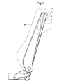
- a backrest for a motor vehicle seat has two side rails 1 and 2 which are of the same mirror image with respect to the center of the backrest and which are pivotally connected in the region of their lower end by means of a schematically shown known articulated fitting and can be fixed in a selectable pivoting position with the cushion support of the associated seat part.
- the side rails 1 and 2 made of sheet steel have a C-like cross-sectional profile, as shown in FIGS. 3 and 4, the two legs 1 'and 1' 'or 2' and 2 '' running parallel to one another and against the other side rail point.
- the yoke part of the profile which is relatively wide in relation to the length of the legs, is stiffened by a wide bead pressed inwards.
- the side rails 1 and 2 therefore have a high bending stiffness in their pivoting direction and a lower stiffness compared to a bend against the other side rail.
- a rigid and kink-resistant spacer 3 is arranged, which is inserted from behind between the side rails and at which is a plastic injection molded part.
- the inclination of the side surface 4 of the spacer 3 is adapted to the inclination of the side rails 1 and 2.
- the spacer 3 can therefore not be moved upwards out of its position between the side rails 1 and 2, although it is not connected to the side rails by means of screws or other connecting elements.
- the side wall 5 "of the strips 5 lies with its front-facing surface on the rear-facing side of the rear leg 1 'or 2' of the two side rails. As far as these two legs project into the area of the cross bars 6, these cross bars are also located on the legs 1 'and 2.
- the spacer 3 including the strips 5 thus protrudes rearward beyond the side rails 1 and 2, in accordance with the thickness of the strips 5.
- a thin, flexible sheet ah which in the exemplary embodiment has a thickness of about 0.4 mm, on the back of the spacer 3.
- the sheet 7 extends beyond the strips 5 to the side rails 1 and 2.
- the protrusion of the strips 5 towards the rear About the side rails 1 and 2 and the amount by which the strips 5 are offset from the side rails 1 and 2 towards the center of the backrest, their distance from each other is smaller than the distance between the side rails, are chosen so that Sheet 7 in each of the two sections extending from the strips 5 to the adjacent side rail 1 or 2 includes an acute angle with the longitudinal center plane of the backrest, which has the size required for torsion-free loading of the side rails 1, 2.
- the zones of the plate 7 which experience a deflection through the strips 5 and the side rails 1, 2 form hinge-like regions which enable the plate 7 to be adjusted to the correct angular size if necessary.
- the sheet 7 lies on the side rails 1, 2, namely on their edge at the transition from the yoke section to the leg 1 'or 2', and is spot welded to the yoke section in the area between this leg and the bead or is otherwise firmly connected.
- the spacer 3 would wedge between the latter and the sheet metal 7 when moving downwards relative to the two side rails.
- the side rails 1 and 2 are not subjected to any torsional stress, but only to a bending stress, the spacer 3 preventing the distance between the two side rails from decreasing, that is to say these be bent against each other. This ensures that the sheet 7 does not bulge significantly from the front even at high loads.
- the spacer 3 is provided on its rear side near its upper edge with a step / which projects backwards and extends over the entire width and which rests on the upper edge of the sheet 7.
- the spacer 3 is therefore supported on the sheet 7 when loaded from above.
- screws 8, which penetrate the sheet 7 and are screwed into the spacer 3 secure the latter against a downward displacement.
- the screws 8 hold the sheet 7 in contact with the rear of the spacer 3.
- Another possibility would be to provide a groove in the step overlapping the upper edge of the sheet 7, which groove receives the upper edge.
- a cap 15 is formed, which covers the upper end of the side rails 1 or 2, so that the side rails can be open at the top.
- the plate 7 extends down to the vicinity of that area of the side rails 1 and 2 in which they carry the joint fitting.
- the sheet 7 together with the side rails 1 and 2 and the spacer 3 forms a shell-like cushion support for the cushion 9 shown in FIG. 1 with a dash-dotted line.
- a side cheek frame or the like can be attached to the side members.
- the spacer 3 not only has stiffening ribs 10 which stiffen the substantially rectangular front facing the back of the seat user.
- the spacer 3 is also provided with two parallel guide channels 11 which run from top to bottom and into which the support rods of a headrest can be inserted.
- the guide channels 11 have a square cross-section, the side length being selected to be the same as the diameter of the usually round support rods, so that they lie practically free of play in the guide channels 11.
- the guide channels 11 are delimited by webs 12 which are spaced apart from one another in the longitudinal direction of the channel and which are equal to the web width. The webs on the front are aligned with the gaps between the webs on the back and vice versa.
- This configuration of the guide channels 11 allows the support rods to have relatively large tolerances.
- the support rods are fixed at the desired height in a known manner by means of a respective leg spring, which can snap into the catches of the support rods and rests on the top of the spacer 3.
- the spacer 3 could have a bearing for a shoulder rest in which corresponding guide channels for the support rods of a head rest would then have to be provided.
- the actuating elements can be provided in the spacer, which are necessary in a backrest, which can be folded forward, for releasing the locking device preventing such folding.
Landscapes
- Engineering & Computer Science (AREA)
- Aviation & Aerospace Engineering (AREA)
- Transportation (AREA)
- Mechanical Engineering (AREA)
- Seats For Vehicles (AREA)
- Chair Legs, Seat Parts, And Backrests (AREA)
Applications Claiming Priority (2)
| Application Number | Priority Date | Filing Date | Title |
|---|---|---|---|
| DE3222505 | 1982-06-16 | ||
| DE3222505A DE3222505C2 (de) | 1982-06-16 | 1982-06-16 | Rückenlehne für Fahrzeugsitze |
Publications (3)
| Publication Number | Publication Date |
|---|---|
| EP0096859A2 true EP0096859A2 (fr) | 1983-12-28 |
| EP0096859A3 EP0096859A3 (en) | 1987-06-03 |
| EP0096859B1 EP0096859B1 (fr) | 1988-08-10 |
Family
ID=6166118
Family Applications (1)
| Application Number | Title | Priority Date | Filing Date |
|---|---|---|---|
| EP83105680A Expired EP0096859B1 (fr) | 1982-06-16 | 1983-06-10 | Dossier pour siège de véhicule |
Country Status (4)
| Country | Link |
|---|---|
| US (1) | US4530541A (fr) |
| EP (1) | EP0096859B1 (fr) |
| JP (1) | JPS5957034A (fr) |
| DE (1) | DE3222505C2 (fr) |
Cited By (2)
| Publication number | Priority date | Publication date | Assignee | Title |
|---|---|---|---|---|
| FR2771977A1 (fr) * | 1997-12-09 | 1999-06-11 | Cesa | Dossier perfectionne de siege de vehicule automobile, notamment de banquette arriere |
| EP1057691A1 (fr) * | 1999-05-27 | 2000-12-06 | TCG UNITECH Aktiengesellschaft | Dossier pour un véhicule automobile |
Families Citing this family (19)
| Publication number | Priority date | Publication date | Assignee | Title |
|---|---|---|---|---|
| DE3521402C1 (de) * | 1985-06-14 | 1986-10-02 | Keiper Recaro GmbH & Co, 5630 Remscheid | Polstertraeger fuer die Rueckenlehne eines Fahrzeugsitzes |
| DE3633012C2 (de) * | 1985-09-30 | 1994-06-23 | Aisin Seiki | Polstersitz für Kraftfahrzeuge |
| IT1284669B1 (it) * | 1996-07-16 | 1998-05-21 | Bruzolo Manifatt Gestind Mb | Appoggiatesta per sedili di autoveicoli. |
| US6056366A (en) * | 1999-02-26 | 2000-05-02 | Lear Corporation | Composite back frame for a vehicle seat and method for distributing seat belt loads |
| WO2003016091A1 (fr) | 2001-08-15 | 2003-02-27 | Dow Global Technologies Inc. | Systeme de siege perfectionne |
| US7128373B2 (en) * | 2002-09-27 | 2006-10-31 | Dow Global Technologies, Inc. | Seating system and method of forming same |
| US7250091B2 (en) * | 2003-02-13 | 2007-07-31 | Dow Global Technologies Inc | Method of forming a seating system |
| US6786544B1 (en) * | 2003-11-07 | 2004-09-07 | Tachi-S Co., Ltd. | Seat back structure of vehicle seat |
| DE102007016690A1 (de) * | 2006-10-27 | 2008-04-30 | Johnson Controls Gmbh | Strukturelement für Fahrzeugsitz |
| DE102007041222A1 (de) * | 2007-08-31 | 2009-03-05 | Lear Corp., Southfield | Fahrzeugsitz-Verbundrahmen |
| JP5254586B2 (ja) * | 2007-10-02 | 2013-08-07 | 富士重工業株式会社 | 車両用シート構造 |
| DE102009033883A1 (de) * | 2009-07-20 | 2011-01-27 | Bayerische Motoren Werke Aktiengesellschaft | Fahrzeugsitz mit einer Rückenlehne, die eine stützende Strebenstruktur aufweist |
| DE102010024715A1 (de) * | 2010-06-23 | 2011-12-29 | Volkswagen Ag | Rückenlehne eines Kraftfahrzeugsitzes |
| US9073468B2 (en) * | 2011-11-14 | 2015-07-07 | Ford Global Technologies, Llc | Vehicle seat bracket assembly |
| DE102013213995B4 (de) * | 2013-07-17 | 2015-03-26 | Johnson Controls Components Gmbh & Co. Kg | Rückenlehne für einen Fahrzeugsitz und Fahrzeugsitz |
| US9776544B2 (en) | 2014-05-20 | 2017-10-03 | Norco Industries, Inc. | Stowable seat |
| JP6411124B2 (ja) * | 2014-08-06 | 2018-10-24 | テイ・エス テック株式会社 | シートバックフレーム |
| US10850643B2 (en) | 2017-09-28 | 2020-12-01 | Norco Industries, Inc. | Sofa base |
| US10596939B2 (en) | 2017-12-13 | 2020-03-24 | Ford Global Technologies, Llc | Polymeric seat cushion frame integrated module attachment system |
Family Cites Families (7)
| Publication number | Priority date | Publication date | Assignee | Title |
|---|---|---|---|---|
| US3043624A (en) * | 1958-11-07 | 1962-07-10 | Mason Ernest Gilbert | Seat for public use |
| US3134627A (en) * | 1962-03-19 | 1964-05-26 | Mason Ernest Gilbert | Seat for public use |
| DE1975071U (de) * | 1967-09-06 | 1967-12-14 | Recaro G M B H & Co | Kraftfahrzeugsitz. |
| DE1954848A1 (de) * | 1969-10-31 | 1971-06-24 | Gerhard Rotter | Sitz,insbesondere fuer Kfz |
| GB1360241A (en) * | 1971-03-15 | 1974-07-17 | Chrysler Uk | Seats |
| DE7327252U (de) * | 1973-07-25 | 1973-11-15 | Opel A Ag | Hoehenverstellvorrichtung fuer kopfstuetzen insbesondere in kraftfahrzeugen |
| FR2515946B1 (fr) * | 1981-11-11 | 1985-10-11 | Keiper Automobiltechnik Gmbh | Cadre de dossier pour sieges, notamment pour sieges de vehicules automobiles |
-
1982
- 1982-06-16 DE DE3222505A patent/DE3222505C2/de not_active Expired
-
1983
- 1983-06-10 EP EP83105680A patent/EP0096859B1/fr not_active Expired
- 1983-06-16 JP JP58106807A patent/JPS5957034A/ja active Granted
- 1983-06-16 US US06/505,420 patent/US4530541A/en not_active Expired - Fee Related
Cited By (2)
| Publication number | Priority date | Publication date | Assignee | Title |
|---|---|---|---|---|
| FR2771977A1 (fr) * | 1997-12-09 | 1999-06-11 | Cesa | Dossier perfectionne de siege de vehicule automobile, notamment de banquette arriere |
| EP1057691A1 (fr) * | 1999-05-27 | 2000-12-06 | TCG UNITECH Aktiengesellschaft | Dossier pour un véhicule automobile |
Also Published As
| Publication number | Publication date |
|---|---|
| JPH0126897B2 (fr) | 1989-05-25 |
| DE3222505C2 (de) | 1986-04-10 |
| EP0096859A3 (en) | 1987-06-03 |
| JPS5957034A (ja) | 1984-04-02 |
| DE3222505A1 (de) | 1983-12-22 |
| EP0096859B1 (fr) | 1988-08-10 |
| US4530541A (en) | 1985-07-23 |
Similar Documents
| Publication | Publication Date | Title |
|---|---|---|
| EP0096859B1 (fr) | Dossier pour siège de véhicule | |
| DE3337910C2 (fr) | ||
| EP0065116B1 (fr) | Siège de véhicule | |
| DE2364797A1 (de) | Verstellbare sitzanordnung fuer ein fahrzeug | |
| EP0082436A2 (fr) | Siège de véhicule | |
| DE19531982A1 (de) | Karosseriestruktur für ein Kraftfahrzeug | |
| DE3613830A1 (de) | Verstellbarer fahrzeugsitz mit einem sicherheitsgurtsystem | |
| DE10012590B4 (de) | Vor einem Laderaum eines Kraftfahrzeuges angeordnete Sitzanordnung | |
| DE2940463A1 (de) | In sitzlaengsrichtung verstellbarer automobilsitz | |
| EP0100880B1 (fr) | Glissière de siège pour le réglage longitudinal de sièges de véhicules | |
| DE2303289A1 (de) | Fahrzeugsitz mit einer ein lehnenpolster tragenden schale | |
| DE2753307A1 (de) | Hoehen- und neigungsverstelleinrichtung fuer fahrzeugsitze | |
| DE8709523U1 (de) | Polsterträger für einen Fahrzeugsitz | |
| DE4303006C2 (de) | Rückenlehne für Fahrzeugsitze, insbesondere Kraftfahrzeugsitze | |
| DE2437172C3 (de) | Verstelleinrichtung für einen längsverschiebbaren Fahrzeugsitz | |
| DE4421946A1 (de) | Rückenlehne eines Kraftfahrzeugsitzes, die aus einem Rückenlehnengestell und einem Polsterteil aufgebaut ist | |
| DE2751110B2 (de) | Fahrgastsitz für Nahverkehrsfahrzeuge | |
| DE3418233C2 (fr) | ||
| DE68923174T2 (de) | Anordnung für fahrzeugsitze. | |
| DE3222506C2 (de) | Rückenlehne für einen Fahrzeugsitz | |
| DE19927532C2 (de) | Mechanismus zum Anbringen eines Sicherheitsgurtes eines mittleren Sitzplatzes von einem Fahrzeugsitz | |
| DE2118229C3 (de) | Gleitführung für einen in Längsrichtung verschiebbaren Fahrzeugsitz | |
| DE2208224B2 (de) | Kopfstütze für Fahrzeugsitze | |
| DE2919715C2 (de) | Beinstütze | |
| DE10129059C1 (de) | Rückenlehnenrahmen eines Kraftfahrzeugsitzes |
Legal Events
| Date | Code | Title | Description |
|---|---|---|---|
| PUAI | Public reference made under article 153(3) epc to a published international application that has entered the european phase |
Free format text: ORIGINAL CODE: 0009012 |
|
| AK | Designated contracting states |
Designated state(s): FR GB IT |
|
| RBV | Designated contracting states (corrected) |
Designated state(s): FR GB IT |
|
| PUAL | Search report despatched |
Free format text: ORIGINAL CODE: 0009013 |
|
| AK | Designated contracting states |
Kind code of ref document: A3 Designated state(s): FR GB IT |
|
| 17P | Request for examination filed |
Effective date: 19870513 |
|
| 17Q | First examination report despatched |
Effective date: 19880119 |
|
| GRAA | (expected) grant |
Free format text: ORIGINAL CODE: 0009210 |
|
| AK | Designated contracting states |
Kind code of ref document: B1 Designated state(s): FR GB IT |
|
| GBT | Gb: translation of ep patent filed (gb section 77(6)(a)/1977) | ||
| ITF | It: translation for a ep patent filed | ||
| ET | Fr: translation filed | ||
| PLBE | No opposition filed within time limit |
Free format text: ORIGINAL CODE: 0009261 |
|
| STAA | Information on the status of an ep patent application or granted ep patent |
Free format text: STATUS: NO OPPOSITION FILED WITHIN TIME LIMIT |
|
| 26N | No opposition filed | ||
| PGFP | Annual fee paid to national office [announced via postgrant information from national office to epo] |
Ref country code: FR Payment date: 19920526 Year of fee payment: 10 |
|
| PGFP | Annual fee paid to national office [announced via postgrant information from national office to epo] |
Ref country code: GB Payment date: 19920601 Year of fee payment: 10 |
|
| ITTA | It: last paid annual fee | ||
| PG25 | Lapsed in a contracting state [announced via postgrant information from national office to epo] |
Ref country code: GB Effective date: 19930610 |
|
| GBPC | Gb: european patent ceased through non-payment of renewal fee |
Effective date: 19930610 |
|
| PG25 | Lapsed in a contracting state [announced via postgrant information from national office to epo] |
Ref country code: FR Effective date: 19940228 |
|
| REG | Reference to a national code |
Ref country code: FR Ref legal event code: ST |