EP0096744A2 - Fitting for a wing arranged to be both swingable about a vertical axis and tiltable about a horizontal axis - Google Patents
Fitting for a wing arranged to be both swingable about a vertical axis and tiltable about a horizontal axis Download PDFInfo
- Publication number
- EP0096744A2 EP0096744A2 EP83104444A EP83104444A EP0096744A2 EP 0096744 A2 EP0096744 A2 EP 0096744A2 EP 83104444 A EP83104444 A EP 83104444A EP 83104444 A EP83104444 A EP 83104444A EP 0096744 A2 EP0096744 A2 EP 0096744A2
- Authority
- EP
- European Patent Office
- Prior art keywords
- tilt
- locking
- locking rod
- fitting according
- tilting
- Prior art date
- Legal status (The legal status is an assumption and is not a legal conclusion. Google has not performed a legal analysis and makes no representation as to the accuracy of the status listed.)
- Withdrawn
Links
- 239000000463 material Substances 0.000 claims description 3
- 210000000078 claw Anatomy 0.000 description 6
- 238000006073 displacement reaction Methods 0.000 description 3
- 230000013011 mating Effects 0.000 description 3
- 230000005540 biological transmission Effects 0.000 description 1
- 238000000034 method Methods 0.000 description 1
- 238000012986 modification Methods 0.000 description 1
- 230000004048 modification Effects 0.000 description 1
- 238000009423 ventilation Methods 0.000 description 1
Images


Classifications
-
- E—FIXED CONSTRUCTIONS
- E05—LOCKS; KEYS; WINDOW OR DOOR FITTINGS; SAFES
- E05C—BOLTS OR FASTENING DEVICES FOR WINGS, SPECIALLY FOR DOORS OR WINDOWS
- E05C17/00—Devices for holding wings open; Devices for limiting opening of wings or for holding wings open by a movable member extending between frame and wing; Braking devices, stops or buffers, combined therewith
- E05C17/02—Devices for holding wings open; Devices for limiting opening of wings or for holding wings open by a movable member extending between frame and wing; Braking devices, stops or buffers, combined therewith by mechanical means
- E05C17/04—Devices for holding wings open; Devices for limiting opening of wings or for holding wings open by a movable member extending between frame and wing; Braking devices, stops or buffers, combined therewith by mechanical means with a movable bar or equivalent member extending between frame and wing
- E05C17/12—Devices for holding wings open; Devices for limiting opening of wings or for holding wings open by a movable member extending between frame and wing; Braking devices, stops or buffers, combined therewith by mechanical means with a movable bar or equivalent member extending between frame and wing consisting of a single rod
- E05C17/24—Devices for holding wings open; Devices for limiting opening of wings or for holding wings open by a movable member extending between frame and wing; Braking devices, stops or buffers, combined therewith by mechanical means with a movable bar or equivalent member extending between frame and wing consisting of a single rod pivoted at one end, and with the other end running along a guide member
- E05C17/28—Devices for holding wings open; Devices for limiting opening of wings or for holding wings open by a movable member extending between frame and wing; Braking devices, stops or buffers, combined therewith by mechanical means with a movable bar or equivalent member extending between frame and wing consisting of a single rod pivoted at one end, and with the other end running along a guide member with braking, clamping or securing means at the connection to the guide member
-
- E—FIXED CONSTRUCTIONS
- E05—LOCKS; KEYS; WINDOW OR DOOR FITTINGS; SAFES
- E05C—BOLTS OR FASTENING DEVICES FOR WINGS, SPECIALLY FOR DOORS OR WINDOWS
- E05C17/00—Devices for holding wings open; Devices for limiting opening of wings or for holding wings open by a movable member extending between frame and wing; Braking devices, stops or buffers, combined therewith
- E05C17/02—Devices for holding wings open; Devices for limiting opening of wings or for holding wings open by a movable member extending between frame and wing; Braking devices, stops or buffers, combined therewith by mechanical means
- E05C17/38—Devices for holding wings open; Devices for limiting opening of wings or for holding wings open by a movable member extending between frame and wing; Braking devices, stops or buffers, combined therewith by mechanical means with a curved rail rigid with the frame for engagement with means on the wing, or vice versa
-
- E—FIXED CONSTRUCTIONS
- E05—LOCKS; KEYS; WINDOW OR DOOR FITTINGS; SAFES
- E05D—HINGES OR SUSPENSION DEVICES FOR DOORS, WINDOWS OR WINGS
- E05D15/00—Suspension arrangements for wings
- E05D15/48—Suspension arrangements for wings allowing alternative movements
- E05D15/52—Suspension arrangements for wings allowing alternative movements for opening about a vertical as well as a horizontal axis
- E05D15/5217—Tilt-lock devices
-
- E—FIXED CONSTRUCTIONS
- E05—LOCKS; KEYS; WINDOW OR DOOR FITTINGS; SAFES
- E05D—HINGES OR SUSPENSION DEVICES FOR DOORS, WINDOWS OR WINGS
- E05D15/00—Suspension arrangements for wings
- E05D15/48—Suspension arrangements for wings allowing alternative movements
- E05D15/52—Suspension arrangements for wings allowing alternative movements for opening about a vertical as well as a horizontal axis
- E05D15/526—Safety devices
-
- E—FIXED CONSTRUCTIONS
- E05—LOCKS; KEYS; WINDOW OR DOOR FITTINGS; SAFES
- E05Y—INDEXING SCHEME ASSOCIATED WITH SUBCLASSES E05D AND E05F, RELATING TO CONSTRUCTION ELEMENTS, ELECTRIC CONTROL, POWER SUPPLY, POWER SIGNAL OR TRANSMISSION, USER INTERFACES, MOUNTING OR COUPLING, DETAILS, ACCESSORIES, AUXILIARY OPERATIONS NOT OTHERWISE PROVIDED FOR, APPLICATION THEREOF
- E05Y2900/00—Application of doors, windows, wings or fittings thereof
- E05Y2900/10—Application of doors, windows, wings or fittings thereof for buildings or parts thereof
- E05Y2900/13—Type of wing
- E05Y2900/148—Windows
Definitions
- the invention relates to a turn-tilt fitting for windows and / or doors, comprising a control handle arranged covered from one in the wing, with a three-position transmission provided linkage with locking rods, one rotatably mounted on the frame Kippschere, a corner bearing and at least two rehachsseite at the D arranged, consisting of a locking member fastened to the linkage and a closure piece fastened to the frame or frame.
- Such turn-tilt fittings have been known for a long time and are built in a variety of forms and modifications.
- a disadvantage of these known tilt and turn fittings is that only a single tilt position, namely a maximum tilt position, which is limited by the tilting scissors, can be set.
- a locking device for windows and doors with tilt and turn sash is known, in which a locking arm latches in the fully tilted position, which prevents the sash from slamming, for example, by wind pressure.
- the invention has for its object to provide a D rehkipp fitting in which different intermediate positions can be set between the closed and fully tilted position of the wing.
- a tilt lock is provided for locking the wing in different tilt positions between fully closed and fully tilted position, wherein according to a preferred embodiment, the tilt lock on the locking rods on the casement and is arranged on the frame.
- a toothed segment can be attached to the displaceable locking bars on at least one side of the wing, a toothed counterclaw is attached to at least one side of the frame and a certain idle stroke of the locking bars can be carried out with the operating handle.
- Conventional turn-tilt fittings are provided, for example, with an operating handle which can be transferred from a downward closed position into a horizontally directed tilted position and then into an upward turned position. However, it is also possible to turn from the downward closed position via a horizontally directed rotary position into an upward tilted position.
- an idle stroke of the locking rods is used either between the closed position and the tilted position or the rotary position and the tilted position.
- This idle stroke of the locking rods makes it possible to raise or lower the toothed segment provided on the locking rods so that the engagement with the toothed counterclaw fixedly arranged on the stick frame can be released. This makes it possible to tilt the wing into any intermediate position in order to bring the cooperating locking parts into engagement with one another by actuating the operating handle with a connected displacement of the locking rods.
- the toothing of the segment is directed upwards on the handle side and downwards on the hinge side.
- a locking device consisting of a toothed segment and a counter-claw on both sides. Since the opposite ver perform a counter-clockwise movement, the arrangement of the locking parts is in opposite directions.
- the toothing of the segment and counterclaw is designed to be self-locking.
- the locking device parts segment and counterclaw can preferably consist of wear-resistant material.
- the tilting lock is arranged on the tilting scissors, a wishbone being rotatably attached to the tilting scissors, the other end of which is pivoted on a hollow locking rod into which one is attached to one end of a torsion bar Brake part engages, wherein at the other end of the torsion bar a control plate with a curved elongated hole is rotatably fastened and in the elongated hole the end of the hinge-side locking rod is guided.
- this locking device it is possible to lock a window or door leaf continuously in any tilt position.
- the position of the tilting shears is controlled by an additional wishbone.
- the wishbone is locked to the window sash by a brake part that is tilted in the hollow locking rod and thus prevents a relative movement between the braking part and the locking rod.
- the brake part is preferably covered with rubber.
- the torsion bar can preferably be non-displaceable in the longitudinal direction by a bolt engaging in the locking bar channel be kept in cash.
- the hollow locking rod, on which the additional wishbone is arranged, moves relatively over the brake part, which is fixedly arranged on the torsion bar. This is therefore secured in the longitudinal direction by the bolt.
- the control plate provided with the curved elongated hole is arranged in a rotationally fixed manner at its outer end.
- the end of the hinge-side locking rod engages in this elongated hole, which preferably has a bolt formed with a roller, so that the roller is guided with low friction in the elongated hole.
- the hollow locking rod to which the wishbone is articulated, is U-shaped in cross-section with leg ends parallel to the central leg and pointing outwards and with the leg ends undercuts of the locking rod channel, which is on the top of the window casement is arranged, engages behind.
- the hollow locking rod has an inner free rectangular cross section and the braking part is also rectangular in cross section.
- the free cross-section of the hollow locking rod is preferably possible for the free cross-section of the hollow locking rod to consist of two semicircles with an intermediate rectangular central part and for the braking part to be provided with correspondingly rounded end faces.
- the brake part is designed without rubber, since the brake part acts like an eccentric within the hollow locking rod.
- a downward projecting bolt projection guided in the wall of the locking rod channel is provided on the braking part, wherein a transverse longitudinal slot can be formed in the locking rod channel as a guide.
- the torsion bar can preferably be designed as a tube and can be rotated by approximately 10 °.
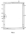
- FIG. 1 shows a tilt-and-turn sash of a window, with a frame 10, a blind or stick frame 12 and an operating handle 14.
- a tilting scissor 16 is shown with broken lines.
- a track bearing 20 is provided at the lower right corner.
- an anti-lift device 24 prevents the sash from being lifted out of the frame in the tilted state.
- the operating handle 14 is shown in full lines in a downward closed position. A horizontal position could mean the tilt position and the vertically upward position could mean the rotary position.
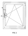
- Fig. 2 shows a schematic representation of a window sash, in which the operating handle 26 in the downward position also represents the closed position, but in the horizontal position, the rotational position.
- the tilt position is assumed in the upward position of the actuating handle.
- the arrow 28 shows an idle stroke that can be carried out with the actuating handle 26 in the tilted position.
- Fig. 3 shows a similar window sash with an operating handle .30, which from the downward The closed position can be moved into the horizontal tilt position and then into the upward rotating position. An idle stroke shown by arrow 32 of up to 90 ° is possible between the closed position and the tilted position. The empty strokes shown in FIGS. 2 and 3 are required to actuate the tilt lock.
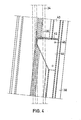
- Fig. 4 shows a first embodiment of a tilt lock with which a window or door leaf can be transferred to different defined tilt positions and locked therein.
- Fig. 4 shows a section of a stick frame 34, on which a mating claw 36 is rigidly attached.
- a section of a casement 38 is shown in a tilted position.
- a locking rod 40 is slidably guided.
- a segment 44 provided with teeth 42 is rigidly attached to this locking rod 40, for example by rivets or screws 46. The segment 44 is in engagement with the counter claw 36 between two teeth 42.
- an idle stroke of the locking bar 40 can take place, in which no other position of the wing is assumed, it is possible to lock the locking bar 40 to move a small area downward, so that the segment 44 fastened to this locking rod moves downward and comes out of the engagement position with the mating claw 36.
- the window sash can be brought into a tilting position which differs from that shown in the exemplary embodiment.
- the locking rod is pulled up again and the mating claw 36 engages between two teeth 42.
- the interlocking between the counter claw and the toothed segment has a certain self-locking, so that no independent, unintentional solution of these parts can take place.
- the parts can be made of wear-resistant material.
- the parts of the tilting lock i.e. the parts with conventional handle movements analogous to FIG. 2, in which the horizontal central position means turning the sash, the counter claw and the segment are installed.
- the central position of the handle means tilting (Fig. 3). This means that a 90 ° empty stroke to the closed position can be fully utilized.
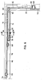
- Fig. 5 shows an embodiment of a tilt lock, in which a stepless adjustment of a tilted wing is possible.
- a tilting scissors 54 is arranged between a window sash 50 and a stick frame 52.
- the tilting scissors 54 is non-deflectable at one end via a joint 56 on the stick frame 52 / and at its other end is provided with a bolt 58 which is in an elongated hole 60 in the locking channel of the Casement 50 is guided.
- a wishbone 62 secures the position of the tilting shear 54 with the wing tilted to the maximum.
- a second wishbone 66 is rotatably attached to the tilting shear 54 via a bolt 64.
- the control arm 66 is rotatably fastened via a bolt 68 to a hollow locking rod 72 running in the sash fold 70.
- One end of a round torsion bar 74 engages in this hollow locking bar 72.
- the torsion bar 74 is rotatable in the locking bar channel by a clamp 76 78 of the wing 50 stored.
- a braking part 80 is arranged, which is held on the torsion bar 74 by a pin 82.
- a ring 84 Arranged around the torsion bar 74 is a ring 84 with a bolt 86 projecting into the wall of the closure rod channel base, which prevents longitudinal displacement of the torsion rod 74 in the closure rod channel.
- a pin 90 with a square neck is fastened via a pin 88.
- a plate 92 is riveted to this square neck.
- Fig: 6 shows a section through the casement.
- the torsion bar 74 held over the clamp 76 can be seen in the locking bar channel 78.
- the torsion bar 74 is designed as a tube and has at its left end the brake part 80 which is guided inside the hollow locking rod 72.
- the brake part 80 is covered with rubber 94. The tolerances between the rubber-coated brake part 80 and the hollow chamber of the locking rod 72 are adjusted so that the hollow locking rod 72 can be easily moved over the brake part.
- the control plate 92 riveted to the other end of the torsion bar 74 extends perpendicular to the torsion bar and is arranged to run laterally parallel to the casement.
- a curved elongated hole 96 is provided, in which a bolt 100 provided with a roller 98 is guided, which is fastened to the upper end of a locking rod 102.
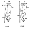
- the control plate 104 shown in FIG. 7 is intended for a tilt and turn fitting in which the central position of the actuating handle means tilting.
- the control plate 104 is attached at its upper end to the square extension 106 on the torsion bar. Above it is indicated a tilting scissors 108, a closing rod channel 109 in dash-dotted lines.
- the control plate 104 is formed with an elongated hole 110, which has approximately the shape of a boomerang. 112, 114 and 116 show possible positions of the upper end 118 of a locking rod, which is provided with a bolt and a roller.
- the lower position 112 corresponds to the closed position of the wing, position 114 to the tilt position and position 116 to the rotary position. Between the position 112 and the position 114, the brake stroke or idle stroke is carried out by the operating handle. When the end 118 is arranged in the position 112, the control plate 104 is pivoted, the torsion bar is rotated and the brake part is thus jammed in the hollow locking rod. During the actuation of the handle from the closed position to the tilting position, the control plate 104 is shifted to the right, so that the torsion bar is brought into its untwisted starting position. After the end 118 has taken the position 114, the wing can be tilted.
- the handle If the handle is now moved again in the direction of the closed position, the end 118 slides downward in the elongated hole 110, as a result of which the control plate 104 is pivoted again to the left. But this is associated with a new twisting of the torsion bar, so that the braking part is canted again braking in the hollow locking rod.
- the operating handle If another tilt position is to be taken, the operating handle must be operated again in the direction of the tilt position, after which the wing ge in the desired position is brought, whereupon the actuating handle is pivoted back into the closed position.
- the elongated hole 110 runs approximately vertically with its upper region, so that the torsion bar is not rotated.
- the control plate 120 shown in FIG. 8 is intended for a turn-tilt fitting in which the central position of the actuating handle means turning (see FIG. 2).
- an elongated hole 122 is formed in the control plate 120, which has a longer upper area.
- the end 118 of the locking rod In the closed position, the end 118 of the locking rod is in an upper position 124, for rotating the wing in an underlying rotary position 126 and for tilting in a tilted position 128.
- the actuating handle In order to lock a wing in any tilted position, the actuating handle is pivoted such that the locking rod is guided with its end 118 downward, whereby the control plate 120 is pivoted to the left, so that the torsion bar is rotated and the brake part is tilted in the hollow locking rod.
- This braking position is defined at 130 at the lower end of the elongated hole 122.
- the locking process of a wing in the tilt position is thus achieved in that the wing is brought into a tilt gap ventilation position, after which the idle stroke is actuated on the actuating handle, so that the wing is braked before closing or opening.
- the linkage, the bolt 118, the curved elongated hole 110 or 122, the control plate 104 or 120 with the torsion bar 74 and the brake part 80 are rotated by approximately 10 °, so that the brake part clamped in the cavity of the locking rod 72.
- the hollow locking rod 72 has that Strive to move over the tilting shear 54 or the wishbone 66. But this is not possible because the locking rod 72 is inhibited by the braced brake part.
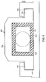
- Fig. 9 shows a first embodiment of a locking rod with the brake part guided therein.
- the locking rod 132 is U-shaped in cross section and is formed with leg ends 136 which are parallel to the center leg 134 and point outward. These leg ends 136 engage behind undercuts 138 which are provided on the closure rod channel 140.
- the locking bar 132 has a free rectangular cross section.
- a brake part 144 is fastened, which is rectangular in cross section and is provided with a rubber casing 146, which is also rectangular in cross section.
- the outer cross section of the rubber jacket 146 corresponds to the inner free cross section of the locking rod 132.
- a hollow locking bar 150 has an outer cross section that corresponds to the hollow locking bar 132.
- the inner free cross-section of the locking rod 150 consists of two semicircles, between which a rectangular central part is provided.
- An elongated brake part 154 is rigidly attached to a torsion bar 152, the end faces of which are formed in the form of circular sections, the radius of which corresponds to the radius of the semicircles of the inner cross section of the locking bar 150. If the torsion bar 152 is rotated, the brake part 154 is also rotated, which is then inside the Locking rod 150 acts as an eccentric and causes jamming between the brake part and locking rod.
- a downwardly projecting pin extension 158 Arranged on the braking part 154 is a downwardly projecting pin extension 158, which is guided in the wall of the locking rod channel 156 and prevents longitudinal displacement of the torsion rod 154 in the locking rod channel.
- the bolt boss 158 is guided in a transverse long slot 160, which allows the wobbling movement of the bolt boss.
Landscapes
- Engineering & Computer Science (AREA)
- Mechanical Engineering (AREA)
- Wing Frames And Configurations (AREA)
- Window Of Vehicle (AREA)
- Control And Other Processes For Unpacking Of Materials (AREA)
Abstract
Bei diesem Drehkippbeschlag ist eine Arretiervorrichtung vorgesehen, die an den Verschlußstangen angeordnet ist. Da zwischen jeweils zwei der drei Stellungen Schließen, Drehen, Kippen des Betätigungsgriffes ein Leerhub vorhanden ist, kann dieser genutzt werden, um über die Verschlußstangen die Arretiervorrichtung zu betätigen. Diese kann dabei entweder seitlich zwischen Flügel und Stockrahmen eines Fensters oder einer Tür oder zwischen Kippschere und im oberen Verschlußstangenkanal geführten Teilen angeordnet sein. Gesichert wird die Kippstellung, die entweder schrittweise oder stufenlos erfolgen kann, durch Betätigen des Griffes aus der Kippstellung in eine der beiden anderen Stellungen Schließen oder Drehen. Die Kipparretierung erfolgt dabei entweder durch Eingriff von Zahnelementen oder durch Verdrehen eines in einer hohen Stange geführten Bremsteils.In this tilt and turn fitting, a locking device is provided, which is arranged on the locking rods. Since there is an idle stroke between two of the three positions closing, turning, tilting the actuating handle, this can be used to actuate the locking device via the locking rods. This can be arranged either laterally between the sash and frame of a window or a door or between tilting scissors and parts guided in the upper locking rod channel. The tilting position, which can either be gradual or stepless, is secured by actuating the handle from the tilting position to one of the other two positions, closing or rotating. The tilt lock occurs either by the engagement of toothed elements or by turning a brake part guided in a high rod.
Description
Die Erfindung betrifft einen Drehkippbeschlag für Fenster und/oder Türen, bestehend aus einem Bedienungsgriff, aus einem im Flügel verdeckt angeordneten, mit einem Dreistellungsgetriebe versehenen Gestänge mit Verschlußstangen, einer am Blendrahmen drehbar angeordneten Kippschere, einem Ecklager und mindestens zwei an der Drehachsseite angeordneten, aus einem am Gestänge befestigten Riegelglied und einem am Blend- oder Stockrahmen befestigten Schließstück gebildeten Verschlüssen.The invention relates to a turn-tilt fitting for windows and / or doors, comprising a control handle arranged covered from one in the wing, with a three-position transmission provided linkage with locking rods, one rotatably mounted on the frame Kippschere, a corner bearing and at least two rehachsseite at the D arranged, consisting of a locking member fastened to the linkage and a closure piece fastened to the frame or frame.
Derartige Drehkippbeschläge sind seit langem bekannt und werden in vielfältigen Formen und Abwandlungen eingebaut. Nachteilig ist bei diesen bekannten Drehkippbeschlägen, daß nur eine einzige Kippstellung, nämlich eine maximale Kippstellung, die durch die Kippschere begrenzt wird, einstellbar ist. Außerdem ist bei den meisten derartigen Beschlägen nachteilig, daß die Kippstellung nicht gesichert ist, so daß der Fenster- oder Türflügel unbeabsichtigt zuschlagen kann. Durch die DE-OS 25 52 939 ist eine Sperrvorrichtung für Fenster und Türen mit Drehkippflügel bekannt, bei der in völlig gekippter Lage ein Sperrarm einklinkt, der verhindert, daß der Flügel beispielsweise durch Winddruck zuschlagen kann.Such turn-tilt fittings have been known for a long time and are built in a variety of forms and modifications. A disadvantage of these known tilt and turn fittings is that only a single tilt position, namely a maximum tilt position, which is limited by the tilting scissors, can be set. In addition, it is disadvantageous in most such fittings that the tilt position is not secured, so that the window or door sash can slam unintentionally. From DE-OS 25 52 939 a locking device for windows and doors with tilt and turn sash is known, in which a locking arm latches in the fully tilted position, which prevents the sash from slamming, for example, by wind pressure.
Der Erfindung liegt die Aufgabe zugrunde, einen Drehkipp- beschlag zu schaffen, bei dem zwischen geschlossener und völlig gekippter Stellung des Flügels verschiedene Zwischenstellungen einstellbar sind.The invention has for its object to provide a D rehkipp fitting in which different intermediate positions can be set between the closed and fully tilted position of the wing.
Die Lösung dieser Aufgabe ist erfindungsgemäß dadurch gekennzeichnet, daß eine Kipparretierung vorgesehen ist zum Arretieren des Flügels in verschiedenen Kippstellungen zwischen völlig geschlossener und völlig gekippter Lage, wobei gemäß einer bevorzugten Ausführungsform die Kipparretierung an den Verschlußstangen am Flügelrahmen und an dem Blendrahmen angeordnet ist.The solution to this problem is characterized in that a tilt lock is provided for locking the wing in different tilt positions between fully closed and fully tilted position, wherein according to a preferred embodiment, the tilt lock on the locking rods on the casement and is arranged on the frame.
Vorzugsweise kann dabei an mindestens einer Seite des Flügels an den verschiebbaren Verschlußstangen ein gezahntes Segment befestigt sein, an mindestens einer Seite des Stockrahmens ist dabei eine gezahnte Gegenklaue befestigt und mit dem Bedienungsgriff ist ein gewisser Leerhub der Verschlußstangen ausführbar. Herkömmliche Drehkippbeschläge sind beispielsweise mit einem Bedienungsgriff versehen, der aus einer nach unten gerichteten Schließstellung in eine waagerecht gerichtete Kippstellung und anschließend in eine nach oben gerichtete Drehstellung überführt werden kann. Es ist aber auch möglich, aus der nach unten gerichteten Schließstellung über eine waagerecht gerichtete Drehstellung in eine nach oben gerichtete Kippstellung zu drehen. Zur Betätigung der Arretiervorrichtung wird dabei ein Leerhub der Verschlußstangen entweder zwischen der Schließstellung und der Kippstellung oder der Drehstellung und der Kippstellung ausgenutzt. Durch diesen Leerhub der Verschlußstangen ist es möglich, das an den Verschlußstangen vorgesehene gezahnte Segment anzuheben bzw. abzusenken, so daß der Eingriff mit der an dem Stockrahmen fest angeordneten gezahnten Gegenklaue gelöst werden kann. Damit ist es möglich, den Flügel in eine beliebige Zwischenstellung zu kippen, um durch Betätigung des Bedienungsgriffs mit verbundenem Verschieben der Verschlußstangen die zusammenwirkenden Arretierteile miteinander in Eingriff zu bringen.Preferably, a toothed segment can be attached to the displaceable locking bars on at least one side of the wing, a toothed counterclaw is attached to at least one side of the frame and a certain idle stroke of the locking bars can be carried out with the operating handle. Conventional turn-tilt fittings are provided, for example, with an operating handle which can be transferred from a downward closed position into a horizontally directed tilted position and then into an upward turned position. However, it is also possible to turn from the downward closed position via a horizontally directed rotary position into an upward tilted position. To actuate the locking device, an idle stroke of the locking rods is used either between the closed position and the tilted position or the rotary position and the tilted position. This idle stroke of the locking rods makes it possible to raise or lower the toothed segment provided on the locking rods so that the engagement with the toothed counterclaw fixedly arranged on the stick frame can be released. This makes it possible to tilt the wing into any intermediate position in order to bring the cooperating locking parts into engagement with one another by actuating the operating handle with a connected displacement of the locking rods.
Vorzugsweise kann dabei vorgesehen sein, daß die Verzahnung des Segments griffseitig nach oben und scharnierseitig nach unten gerichtet ist. Bei größeren Fenster- bzw. Türflügeln empfiehlt es sich, beidseitig eine Arretiervorrichtung aus gezahntem Segment und Gegenklaue vorzusehen. Da die gegenüberliegenden Verschlußstangen eine gegenläufige Bewegung durchführen, ist entsprechend die Anordnung der Arretierteile gegensinnig.It can preferably be provided that the toothing of the segment is directed upwards on the handle side and downwards on the hinge side. In the case of larger window or door sashes, it is advisable to provide a locking device consisting of a toothed segment and a counter-claw on both sides. Since the opposite ver perform a counter-clockwise movement, the arrangement of the locking parts is in opposite directions.
Um die Arretierung in einer Raststellung zu gewährleisten, kann vorgesehen sein, daß die Verzahnung von Segment und Gegenklaue selbsthemmend ausgebildet ist. Die Arretiervorrichtungsteile Segment und Gegenklaue können dabei bevorzugt aus verschleißfestem Material bestehen.In order to ensure the locking in a latching position, it can be provided that the toothing of the segment and counterclaw is designed to be self-locking. The locking device parts segment and counterclaw can preferably consist of wear-resistant material.
Gemäß einer bevorzugten weiteren Ausbildung der Erfindung kann vorgesehen sein, daß die Kipparretierung an der Kippschere angeordnet ist, wobei an der Kippschere ein Querlenker drehbar befestigt ist, dessen anderes Ende drehbar an einer hohlen Verschlußstange angelenkt ist, in welche ein an einem Ende eines Torsionsstabs befestigtes Bremsteil eingreift, wobei am anderen Ende des Torsionsstabs eine Steuerplatte mit einem kurvenförmigen Langloch drehfest befestigt ist und in dem Langloch das Ende der scharnierseitig im Rahmen geführten Verschlußstange geführt ist. Mit Hilfe dieser Arretiervorrichtung ist es möglich, einen Fenster- oder Türflügel stufenlos in einer beliebigen Kippstellung zu arretieren. Dabei wird die Stellung der Kippschere über einen zusätzlichen Querlenker gesteuert. Die Arretierung des Querlenkers an dem Fensterflügel erfolgt dabei über ein Bremsteil, das sich in der hohlen Verschlußstange verkantet und somit eine Relativbewegung zwischen Bremsteil und Verschlußstange verhindert.According to a preferred further embodiment of the invention, it can be provided that the tilting lock is arranged on the tilting scissors, a wishbone being rotatably attached to the tilting scissors, the other end of which is pivoted on a hollow locking rod into which one is attached to one end of a torsion bar Brake part engages, wherein at the other end of the torsion bar a control plate with a curved elongated hole is rotatably fastened and in the elongated hole the end of the hinge-side locking rod is guided. With the help of this locking device it is possible to lock a window or door leaf continuously in any tilt position. The position of the tilting shears is controlled by an additional wishbone. The wishbone is locked to the window sash by a brake part that is tilted in the hollow locking rod and thus prevents a relative movement between the braking part and the locking rod.
Um eine gute Reibwirkung an den inneren Wandungen der hohlen Verschlußstange zu erreichen, ist das Bremsteil vorzugsweise mit Gummi überzogen. Die Torsionsstange kann vorzugsweise durch einen in den Verschlußstangenkanal eingreifenden Bolzen in Längsrichtung unverschiebbar gehalten sein. Die hohle Verschlußstange, an der der zusätzliche Querlenker angeordnet ist, bewegt sich relativ über das Bremsteil, welches fest an der Torsionsstange angeordnet ist. Diese ist deshalb durch den Bolzen in Längsrichtung gesichert.In order to achieve a good friction effect on the inner walls of the hollow locking rod, the brake part is preferably covered with rubber. The torsion bar can preferably be non-displaceable in the longitudinal direction by a bolt engaging in the locking bar channel be kept in cash. The hollow locking rod, on which the additional wishbone is arranged, moves relatively over the brake part, which is fixedly arranged on the torsion bar. This is therefore secured in the longitudinal direction by the bolt.
Zur Steuerung des Torsionsstabs ist an dessen äußerem Ende die mit dem kurvenförmigen Langloch versehene Steuerplatte drehfest angeordnet. In dieses Langloch greift das Ende der scharnierseitigenVerschlußstange ein, welches vorzugsweise einen mit einer Rolle ausgebildeten Bolzen aufweist, so daß die Rolle in dem Langloch reibungsarm geführt ist. Bei Umkehrung der Bedienungsgriffsfunktionen ist es natürlich möglich, griffseitige und scharnierseitige Verschlußstangen bzw. die entsprechenden Teile der Arretiervorrichtung zu vertauschen.To control the torsion bar, the control plate provided with the curved elongated hole is arranged in a rotationally fixed manner at its outer end. The end of the hinge-side locking rod engages in this elongated hole, which preferably has a bolt formed with a roller, so that the roller is guided with low friction in the elongated hole. When the operating handle functions are reversed, it is of course possible to interchange the locking rods on the handle side and the hinge side or the corresponding parts of the locking device.
Gemäß einer bevorzugten Ausführungsform kann vorgesehen sein, daß die hohle Verschlußstange, an der der Querlenker angelenkt ist, im Querschnitt U-förmig mit zum Mittelschenkel parallelen, nach außen weisenden Schenkelenden ausgebildet ist und mit den Schenkelenden Hinterschneidungen des Verschlußstangenkanals, der an der Oberseite des Fensterflügelrahmens angeordnet ist, hintergreift. Die hohle Verschlußstange weist dabei einen inneren freien rechteckigen Querschnitt auf und das Bremsteil ist im Querschnitt ebenfalls rechteckig ausgebildet.According to a preferred embodiment, it can be provided that the hollow locking rod, to which the wishbone is articulated, is U-shaped in cross-section with leg ends parallel to the central leg and pointing outwards and with the leg ends undercuts of the locking rod channel, which is on the top of the window casement is arranged, engages behind. The hollow locking rod has an inner free rectangular cross section and the braking part is also rectangular in cross section.
Vorzugsweise ist es möglich, daß der freie Querschnitt der hohlen Verschlußstange aus zwei Halbkreisen mit dazwischenliegendem, rechteckigem Mittelteil besteht und daß das Bremsteil mit entsprechend abgerundeten Endflächen versehen ist. In diesem Falle ist es möglich, daß das Bremsteil ohne Gummi ausgebildet ist, da das Bremsteil innerhalb der hohlen Verschlußstange wie ein Exzenter wirkt. Um die Verschiebung des Torsionsstabes in Längsrichtung zu verhindern, kann vorgesehen sein, daß an dem Bremsteil ein nach unten abstehender, in der Wandung des Verschlußstangenkanals geführter Bol-' zenansatz vorgesehen ist, wobei als Führung ein quer verlaufender Längsschlitz in dem Verschlußstangenkanal ausgebildet sein kann.It is preferably possible for the free cross-section of the hollow locking rod to consist of two semicircles with an intermediate rectangular central part and for the braking part to be provided with correspondingly rounded end faces. In this case it is possible that the brake part is designed without rubber, since the brake part acts like an eccentric within the hollow locking rod. In order to prevent the torsion bar from shifting in the longitudinal direction, it can be provided that a downward projecting bolt projection guided in the wall of the locking rod channel is provided on the braking part, wherein a transverse longitudinal slot can be formed in the locking rod channel as a guide.
Der Torsionsstab kann vorzugsweise als Rohr ausgebildet und um etwa 10° verdrehbar sein.The torsion bar can preferably be designed as a tube and can be rotated by approximately 10 °.
Die Erfindung wird im folgenden anhand mehrerer Ausführungsbeispiele unter Bezugnahme auf die Zeichnung näher erläutert.Es zeigen:
- Fig. 1 eine Ansicht auf einen Drehkippflügel eines Fensters bzw. einer Tür,
- Fig. 2 eine schematische Ansicht auf eine erste Ausführungsform eines Flügels mit durch : den Betätigungsgriff gesteuerter Kipparretierung, .
- Fig. 3 eine schematische Ansicht auf eine zweite Ausführungsform eines Flügels mit durch einen Betätigungsgriff gesteuerter Kipparretierung,
- Fig. 4 eine erste Ausführungsform einer Kipparretierung,
- Fig. 5 eine zweite Ausführungsform einer Kipparretierung,
- Fig. 6 einen Schnitt gemäß der Linie VI-VI von Fig. 5,
- Fig. 7 und 8 Ausführungsformen von Steuerplatten,
- Fig. 9 einen Schnitt durch ein Bremsteil gemäß der Linie IX-IX von Fig. 6 und
- Fig. 10 einen Schnitt durch eine andere Ausführungsform eines Bremsteils.
- 1 is a view of a tilt and turn sash of a window or a door,
- 2 shows a schematic view of a first embodiment of a wing with a tilting lock controlled by the actuating handle.
- 3 shows a schematic view of a second embodiment of a wing with a tilt lock controlled by an actuating handle,
- 4 shows a first embodiment of a tilt lock,
- 5 shows a second embodiment of a tilt lock,
- 6 shows a section along the line VI-VI of FIG. 5,
- 7 and 8 embodiments of control plates,
- Fig. 9 shows a section through a brake part along the line IX-IX of Fig. 6 and
- Fig. 10 shows a section through another embodiment of a braking part.
Fig. 1 zeigt einen Drehkippflügel eines Fensters, mit einem Rahmen 10, einem Blend- oder Stockrahmen 12 und einem Bedienungsgriff 14. Im rechten oberen Bereich des Flügelrahmens 10 ist eine Kippschere 16 mit unterbrochenen Linien dargestellt. Im geschlossenen Zustand des Flügels ist dieser durch Verrieglungspunkte 18 gesichert. An der rechten unteren Ecke ist ein Spurlager 20 vorgesehen. Oberhalb des Griffs 14 ist eine Fehlbedienungssicherung 22 angeordnet, eine Aushebesicherung 24 verhindert, daß der Flügel in gekipptem Zustand aus dem Rahmen gehoben werden kann. Der Betätigungsgriff 14 ist mit vollen Linien in einer nach unten gerichteten Schließstellung dargestellt. Eine waagerechte Stellung könnte die Kippstellung und die senkrecht nach oben gerichtete Stellung die Drehstellung bedeuten.1 shows a tilt-and-turn sash of a window, with a
Fig. 2 zeigt in schematischer Darstellung einen Fensterflügel, bei dem der Betätigungsgriff 26 in der nach unten gerichteten Stellung ebenfalls die Schließstellung darstellt, in der waagerechten Stellung aber die Drehstellung. In der nach oben gerichteten Stellung des Betätigungsgriffes wird die Kippstellung eingenommen. Durch den Pfeil 28 ist ein Leerhub dargestellt, der mit dem Betätigungsgriff 26 in der Kippstellung ausgeführt werden kann.Fig. 2 shows a schematic representation of a window sash, in which the
Fig. 3 zeigt einen ähnlichen Fensterflügel mit einem Betätigungsgriff .30, der aus der nach unten gerichteten Schließstellung in die waagerechte Kippstellung und anschließend in die nach oben gerichtete Drehstellung überführt werden kann. Zwischen Schließstellung und Kippstellung ist dabei ein durch den Pfeil 32 gezeigter Leerhub bis zu 90° möglich. Die in den Fig. 2 und 3 gezeigten Leerhübe sind zur Betätigung der Kipparretierung erforderlich.Fig. 3 shows a similar window sash with an operating handle .30, which from the downward The closed position can be moved into the horizontal tilt position and then into the upward rotating position. An idle stroke shown by
Fig. 4 zeigt eine erste Ausführungsform einer Kipparretierung, mit der ein Fenster oder Türflügel in verschiedene definierte Kippstellungen überführt und darin arretiert werden kann. Fig. 4 zeigt einen Ausschnitt eines Stockrahmens 34, an dem eine Gegenklaue 36 starr befestigt ist. Ein Ausschnitt eines Flügelrahmens 38 ist in einer gekippten Stellung gezeigt. Im Rahmen des Flügels ist eine Verschlußstange 40 verschiebbar geführt. An dieser Verschlußstange 40 ist ein mit Zähnen 42 versehenes Segment 44 beispielsweise durch Nieten oder Schrauben 46 starr befestigt. Das Segment 44 ist dabei zwischen zwei Zähnen 42 mit der Gegenklaue 36 in Eingriff. Da zwischen zwei Stellungen, beispielsweise zwischen der Schließstellung und der Kippstellung bzw. zwischen der Drehstellung und der Kippstellung mit Hilfe des Betätigungsgriffes ein Leerhub der Verschlußstange 40 erfolgen kann, bei dem keine andere Stellung des Flügels eingenommen wird, ist es möglich, die Verschlußstange 40 um einen kleinen Bereich nach unten zu verschieben, so daß sich das an dieser Verschlußstange befestigte Segment 44 mit nach unten bewegt und aus der Eingriffsstellung mit der Gegenklaue 36 gelangt. Jetzt kann der Fensterflügel in eine Kippstellung gebracht werden, die von der im Ausführungsbeispiel gezeigten abweicht. Nach anschließender gegenläufiger Betätigung des Betätigungsgriffes wird die Verschlußstange wieder nach oben gezogen und die Gegenklaue 36 gelangt zwischen zwei Zähnen 42 in Eingriff. Die Verzahnung zwischen der Gegenklaue und dem mit Zähnen versehenen Segment weist dabei eine gewisse Selbsthemmung auf, so daß keine selbständige, unbeabsichtigte Lösung dieser Teile erfolgen kann. Ausserdem können die Teile aus verschleißfestem Material ausgebildet sein.Fig. 4 shows a first embodiment of a tilt lock with which a window or door leaf can be transferred to different defined tilt positions and locked therein. Fig. 4 shows a section of a stick frame 34, on which a
Bei Betätigungsgriffen, die eine genügende Hubreserve aufweisen, können in die Beschläge mit herkömmlichen Griffbewegungen analog Fig. 2, bei welchen die waagerechte Mittelstellung Drehen des Flügels bedeutet, ohne grosse Schwierigkeiten die Teile der Kipparretierung, d.h. die Gegenklaue und das Segment eingebaut werden. Bei Handgriffen mit wenig oder gar keiner Hubreserve ist es vorteilhaft, den Beschlag so zu konstruieren, daß die Mittelstellung des Handgriffs Kippen bedeutet (Fig. 3). Somit kann dann ein 90°-Leerhub zur Geschlossen-Stellung voll ausgenutzt werden.In the case of actuating handles which have a sufficient stroke reserve, the parts of the tilting lock, i.e. the parts with conventional handle movements analogous to FIG. 2, in which the horizontal central position means turning the sash, the counter claw and the segment are installed. For handles with little or no stroke reserve, it is advantageous to design the fitting so that the central position of the handle means tilting (Fig. 3). This means that a 90 ° empty stroke to the closed position can be fully utilized.
Fig. 5 zeigt eine Ausführungsform einer Kipparretierung, bei der eine stufenlose Einstellung eines gekippten Flügels möglich ist. Zwischen einem Fensterflügel 50 und einem Stockrahmen 52 ist eine Kippschere 54 angeordnete Die Kippschere 54 ist an einem Ende über ein Gelenk 56 unverangelenkt schieblich an dem Stockrahmen 52/und an ihrem anderen Ende mit einem Bolzen 58 versehen, der in einem Langloch 60 im Verschlußkanal des Flügelrahmens 50 geführt ist. Ein Querlenker 62 sichert die Lage der Kippschere 54 bei maximal gekipptem Flügel.Fig. 5 shows an embodiment of a tilt lock, in which a stepless adjustment of a tilted wing is possible. Between a
An der Kippschere 54 ist über einen Bolzen 64 ein zweiter Querlenker 66 drehbar befestigt. An seinem anderen Ende ist der Querlenker 66 über einen Bolzen 68 an einer im Flügelfalz 70 laufenden hohlen Verschlußstange 72 drehbar befestigt. In diese hohle Verschlußstange 72 greift ein Ende eines runden Torsionsstabes 74. Der Torsionsstab 74 ist durch eine Schelle 76 drehbar im Verschlußstangenkanal 78 des Flügels 50 gelagert. An dem in die hohle Verschlußstange 72 hineinragende Ende des Torsionsstabes 74 ist ein Bremsteil 80 angeordnet, das durch einen Stift 82 an dem Torsionsstab 74 gehalten wird. Um den Torsionsstab 74 ist ein Ring 84 mit einem in die Wandung des Verschlußstangenkanalgrundes ragenden Bolzen 86 angeordnet, welcher eine Längsverschiebung des Torsionsstabes 74 in dem Verschlußstangenkanal verhindert. Am in der Figur gezeigten rechten Ende des Torsionsstabes 74 ist über einen Stift 88 ein Bolzen 90 mit quadratischem Ansatz befestigt.Auf diesem quadratischen Ansatz ist eine Platte 92 angenietet.A
Fig: 6 zeigt einen Schnitt durch den Flügelrahmen. In dem Verschlußstangenkanal 78 ist der über die Schelle 76 gehaltene Torsionsstab 74 zu sehen. Der Torsionsstab 74 ist als Rohr ausgebildet und weist an seinem linken Ende das Bremsteil 80 auf, das im Inneren der hohlen Verschlußstange 72 geführt ist. Um eine gute Reibwirkung an den inneren Wandungen der hohlen Verschlußstange 72 zu erreichen, ist das Bremsteil 80 mit Gummi 94 überzogen. Die Toleranzen zwischen dem gummiummantelten Bremsteil 80 und der Hohlkammer der Verschlußstange 72 sind dabei so abgestimmt, daß sich die hohle Verschlußstange 72 leicht über das Bremsteil hinweg verschieben läßt.Fig: 6 shows a section through the casement. The
Aus Fig. 6 ist zu sehen, daß der Bolzen 86, der an dem Ring 84 angeordnet ist, im Verschlußstangenkanalgrund geführt ist.From Fig. 6 it can be seen that the
Die am anderen Ende des Torsionsstabes 74 angenietete Steuerplatte 92 verläuft senkrecht zu dem Torsionsstab und ist nach unten seitlich parallel zum Flügelrahmen verlaufend angeordnet. In der Steuerplatte 92 ist ein kurvenförmig ausgebildetes Langloch 96 vorgesehen, in dem ein mit einer Rolle 98 versehener Bolzen 100 geführt ist, der an dem oberen Ende einer Verschlußstange 102 befestigt ist.The
Fig. 7 und 8 zeigen zwei Ausführungsformen von Steuerplatten. Die in Fig. 7 gezeigte Steuerplatte 104 ist für einen Drehkippbeschlag gedacht, bei der die Mittelstellung des Betätigungsgriffes Kippen bedeutet. Die Steuerplatte 104 ist an ihrem oberen Ende an dem quadratischen Ansatz 106 an dem Torsionsstab befestigt. Darüber ist angedeutet eine Kippschere 108, in strichpunktierten Linien ein Verschlußstangenkanal 109. Im unteren Bereich ist die Steuerplatte 104 mit einem Langloch 110 ausgebildet, das etwa die Form eines Bumerangs aufweist. Mit 112, 114 und 116 sind mögliche Stellungen des mit einem Bolzen und einer Rolle versehenen oberen Endes 118 einer Verschlußstange dargestellt. Die untere Stellung 112 entspricht der Schließstellung des Flügels, die Stellung 114 der Kippstellung und die Stellung 116 der Drehstellung. Zwischen der Stellung 112 und der Stellung 114 wird der Bremshub bzw. Leerhub durch den Betätigungsgriff ausgeführt. Wenn das Ende 118 in der Stellung 112 angeordnet ist, ist die Steuerplatte 104 verschwenkt, der Torsionsstab verdreht und damit das Bremsteil in der hohlen Verschlußstange verklemmt. Während der Betätigung des Griffes aus der Schließstellung in die Kippstellung wird die Steuerplatte 104 nach rechts verschoben, so daß der Torsionsstab in seine unverdrehte Ausgangslage überführt wird. Nachdem das Ende 118 die Stellung 114 eingenommen hat, kann der Flügel gekippt werden. Wird jetzt der Griff wieder in Richtung Schließstellung bewegt, gleitet das Ende 118 in dem Langloch 110 nach unten, wodurch die Steuerplatte 104 wieder nach links verschwenkt wird. Das ist aber mit einem erneuten Verdrehen des Torsionsstabes verbunden, so daß das Bremsteil wieder bremsend in der hohlen Verschlußstange verkantet wird. Wenn eine andere Kippstellung eingenommen werden soll, muß der Betätigungsgriff wieder in Richtung Kippstellung betätigt werden, wonach der Flügel in die gewünschte Stellung gebracht wird, worauf anschließend der Betätigungsgriff wieder in die Schließstellung verschwenkt wird. Beim Übergang von der Kipp- in die Drehstellung verläuft das Langloch 110 mit seinem oberen Bereich etwa senkrecht, so daß keine Verdrehung des Torsionsstabes erfolgt.7 and 8 show two embodiments of control plates. The
Die in Fig. 8 gezeigte Steuerplatte 120 ist für einen Drehkippbeschlag gedacht, bei dem die Mittelstellung des Betätigungsgriffes Drehen bedeutet (siehe Fig. 2). In diesem Fall ist ein Langloch 122 in der Steuerplatte 120 ausgebildet, das einen längeren oberen Bereich aufweist.The
In der Schließstellung ist dabei das Ende 118 der Verschlußstange in einer oberen Stellung 124, zum Drehen des Flügels in einer darunterliegenden Drehstellung 126 und zum Kippen in einer Kippstellung 128. Um einen Flügel in irgendeiner gekippten Stellung zu arretieren, wird der Betätigungsgriff so verschwenkt, daß die Verschlußstange mit ihrem Ende 118 nach unten geführt wird, wodurch die Steuerplatte 120 nach links verschwenkt wird, so daß der Torsionsstab verdreht wird und das Bremsteil in der hohlen Verschlußstange verkantet. Diese Bremsstellung ist mit 130 am unteren Ende des Langlochs 122 definiert.In the closed position, the
Der Arretiervorgang eines Flügels in der Kippstellung wird also dadurch erreicht, daß der Flügel in eine Kippspaltlüftungsstellung gebracht wird, wonach am Betätigungsgriff der Leerhub betätigt wird, so daß der Flügel vor Zu- oder Aufschlagen abgebremst wird. Durch die Betätigung des Betätigungsgriffes im Leerhub wird über das Gestänge, den Bolzen 118, dem kurvenartigen Langloch 110 bzw. 122, die Steuerplatte 104 bzw. 120 mit dem Torsionsstab 74 und dem Bremsteil 80 um ca. 10° gedreht, so daß sich das Bremsteil im Hohlraum der Verschlußstange 72 verspannt. Wenn am Flügel gedrückt oder gezogen wird, so hat die hohle Verschlußstange 72 das Bestreben, sich über die Kippschere 54 bzw. die Querlenker 66 zu verschieben. Das ist aber nicht möglich, da die Verschlußstange 72 durch das verspannte Bremsteil gehemmt wird.The locking process of a wing in the tilt position is thus achieved in that the wing is brought into a tilt gap ventilation position, after which the idle stroke is actuated on the actuating handle, so that the wing is braked before closing or opening. By actuating the actuating handle in the idle stroke, the linkage, the
Fig. 9 zeigt eine erste Ausführungsform einer Verschlußstange mit darinnen geführtem Bremsteil. Die Verschlußstange 132 ist im Querschnitt U-förmig und mit zum Mittelschenkel 134 parallelen, nach außen gerichteten Schenkelenden 136 ausgebildet. Diese Schenkelenden 136 hintergreifen Hinterschneidungen 138, die an dem Verschlußstangenkanal 140 vorgesehen sind. Im Inneren weist die Verschlußstange 132 einen freien rechteckigen Querschnitt auf. An einer Torsionsstange 142 ist ein Bremsteil 144 befestigt, das im Querschnitt rechteckig ist und mit einer im Querschnitt ebenfalls rechteckigen Gummiummantelung 146 versehen ist. Der äußere Querschnitt der Gummiummantelung 146 entspricht dem inneren freien Querschnitt der Verschlußstange 132. Wenn die Torsionsstange 142 verdreht wird, wird die Gummiummantelung 146 an die Innenwandung der hohlen Verschlußstange 132 gepreßt, so daß eine Bremswirkung zwischen Bremsteil und Verschlußstange erfolgt.Fig. 9 shows a first embodiment of a locking rod with the brake part guided therein. The locking
Fig. 10 zeigt eine andere Ausführungsform eines Bremsteils. Eine hohle Verschlußstange 150 weist einen äußeren Querschnitt auf, der der hohlen Verschlußstange 132 entspricht. Der innere freie Querschnitt der Verschlußstange 150 besteht aus zwei Halbkreisen, zwischenjjdenen ein rechteckiger Mittelteil vorgesehen ist. An einer Torsionsstange 152 ist ein längliches Bremsteil 154 starr befestigt, dessen Endflächen in Form von Kreisabschnitten ausgebildet sind, deren Radius dem Radius der Halbkreise des inneren Querschnitts der Verschlußstange 150 entsprechen. Wenn der Torsionsstab 152 verdreht wird, wird auch das Bremsteil 154 mitverdreht, das dann im Inneren der VerschluBstange 150 wie ein Exzenter wirkt und eine Verklemmung zwischen Bremsteil und Verschlußstange hervorruft. An dem Bremsteil 154 ist ein nach unten abstehender, in der Wandung des Verschlußstangenkanals 156 geführter Bolzenansatz 158 angeordnet, der eine Längsverschiebung der Torsionsstange 154 in dem Verschlußstangenkanal verhindert. Der Bolzenänsatz 158 ist dabei in einem quer laufenden Langschlitz 160, welcher die Taumelbewegung des Bolzenansatzes zuläßt, geführt.10 shows another embodiment of a braking part. A
Claims (10)
Applications Claiming Priority (2)
| Application Number | Priority Date | Filing Date | Title |
|---|---|---|---|
| DE3222678 | 1982-06-16 | ||
| DE3222678A DE3222678C2 (en) | 1982-06-16 | 1982-06-16 | Tilt & Turn hardware |
Publications (2)
| Publication Number | Publication Date |
|---|---|
| EP0096744A2 true EP0096744A2 (en) | 1983-12-28 |
| EP0096744A3 EP0096744A3 (en) | 1985-05-22 |
Family
ID=6166217
Family Applications (1)
| Application Number | Title | Priority Date | Filing Date |
|---|---|---|---|
| EP83104444A Withdrawn EP0096744A3 (en) | 1982-06-16 | 1983-05-05 | Fitting for a wing arranged to be both swingable about a vertical axis and tiltable about a horizontal axis |
Country Status (4)
| Country | Link |
|---|---|
| US (1) | US4541200A (en) |
| EP (1) | EP0096744A3 (en) |
| JP (1) | JPS594772A (en) |
| DE (1) | DE3222678C2 (en) |
Families Citing this family (11)
| Publication number | Priority date | Publication date | Assignee | Title |
|---|---|---|---|---|
| JPH0513887Y2 (en) * | 1986-11-20 | 1993-04-13 | ||
| FR2644504B2 (en) * | 1988-09-26 | 1991-05-24 | Ferco Int Usine Ferrures | FITTING FOR DOOR, WINDOW OR THE LIKE |
| IT1235293B (en) * | 1989-06-01 | 1992-06-26 | Otlav Spa | DEVICE FOR OPENING AND WINDOW DOORS OF A WINDOW OR A WINDOW DOOR. |
| US5881498A (en) * | 1997-09-27 | 1999-03-16 | Thermo-Roll Window Corp. | Tilt and turn window lock system |
| NZ336579A (en) * | 1999-07-05 | 2001-11-30 | Interlock Group Ltd | Window closer which moves mounting hinge of window |
| DE20002467U1 (en) * | 2000-02-11 | 2000-05-04 | Gretsch-Unitas GmbH Baubeschläge, 71254 Ditzingen | Tilt & Turn hardware |
| DE10113784A1 (en) * | 2001-03-21 | 2002-10-02 | Micro Mechatronic Technologies | Window or door design fits frame with side parallel movement modules and side tipping modules and top swivel element all controlled off single motor for tip slide and pivot actions. |
| US7325359B2 (en) * | 2004-05-28 | 2008-02-05 | Truth Hardware Corporation | Projection window operator |
| US8549789B2 (en) * | 2005-10-24 | 2013-10-08 | Andersen Corporation | Hidden window retainer system for doors |
| ITTO20060434A1 (en) * | 2006-06-15 | 2007-12-16 | Savio Spa | "DRIVE UNIT FOR WINDOWS" |
| WO2016045113A1 (en) * | 2014-09-28 | 2016-03-31 | 李增榜 | Casement hung window |
Citations (2)
| Publication number | Priority date | Publication date | Assignee | Title |
|---|---|---|---|---|
| EP0051309A2 (en) * | 1980-11-03 | 1982-05-12 | Aug. Winkhaus GmbH & Co. KG | Window |
| DE3043925A1 (en) * | 1980-11-03 | 1982-06-03 | Fa. Aug. Winkhaus, 4404 Telgte | Narrow gap window opening securing mechanism - has appropriate bearings and stop block settings, with synchronised drive rods |
Family Cites Families (11)
| Publication number | Priority date | Publication date | Assignee | Title |
|---|---|---|---|---|
| DE1257036B (en) * | 1961-09-13 | 1967-12-21 | Otkn Puu Osakeyhtioe | Opening device for turning or swinging sashes of windows |
| DE1708366A1 (en) * | 1967-11-15 | 1971-05-19 | Siegenia Frank Kg | Locking device for the wings of windows, doors or the like. |
| DE1977333U (en) * | 1967-11-15 | 1968-01-18 | Jaeger Frank K G | LOCKING DEVICE FOR THE LEAF OF WINDOWS, DOORS OR. DGL. |
| US3911621A (en) * | 1973-10-23 | 1975-10-14 | Extrudart Metal Products Inc | Multi-purpose window |
| DE2451556A1 (en) * | 1974-10-30 | 1976-05-06 | Siegenia Frank Kg | Opening position adjustment device for window or door - lug-shaped catch and plate shaped locking member |
| DE2602191A1 (en) * | 1976-01-21 | 1977-07-28 | Goetz Metallbau Gmbh | Stay for tilting and rotating windows - has scissor linkage with sliding actuator and spring loaded ratchet |
| DE2630720A1 (en) | 1976-07-08 | 1978-01-12 | Martin Philipp | Stay coupling for window or door - has coupling halves mounted on moving and fixed frames to give relative locking |
| US4074462A (en) * | 1976-12-06 | 1978-02-21 | Extrudart Metal Products, Inc. | Multi-position window |
| DE7708222U1 (en) * | 1977-03-17 | 1977-06-30 | Siegenia-Frank Kg, 5900 Siegen | GAP VENTILATION DEVICE FOR SASH WINDOWS |
| DE2750073A1 (en) * | 1977-11-09 | 1979-05-10 | Schuermann & Co Heinz | WINDOW WITH TILT & TURN FITTING |
| US4339892A (en) * | 1980-10-09 | 1982-07-20 | Flour City Architectural Metals | Safety window of the tilt and turn type |
-
1982
- 1982-06-16 DE DE3222678A patent/DE3222678C2/en not_active Expired
-
1983
- 1983-05-05 EP EP83104444A patent/EP0096744A3/en not_active Withdrawn
- 1983-06-14 US US06/504,146 patent/US4541200A/en not_active Expired - Lifetime
- 1983-06-15 JP JP58108521A patent/JPS594772A/en active Pending
Patent Citations (2)
| Publication number | Priority date | Publication date | Assignee | Title |
|---|---|---|---|---|
| EP0051309A2 (en) * | 1980-11-03 | 1982-05-12 | Aug. Winkhaus GmbH & Co. KG | Window |
| DE3043925A1 (en) * | 1980-11-03 | 1982-06-03 | Fa. Aug. Winkhaus, 4404 Telgte | Narrow gap window opening securing mechanism - has appropriate bearings and stop block settings, with synchronised drive rods |
Also Published As
| Publication number | Publication date |
|---|---|
| EP0096744A3 (en) | 1985-05-22 |
| DE3222678C2 (en) | 1986-05-22 |
| JPS594772A (en) | 1984-01-11 |
| US4541200A (en) | 1985-09-17 |
| DE3222678A1 (en) | 1983-12-29 |
Similar Documents
| Publication | Publication Date | Title |
|---|---|---|
| DE2920581C2 (en) | Additional locking, in particular central locking, for windows, doors or the like. | |
| DE2603240C2 (en) | Fitting for a tiltable and sliding sash of windows, doors or the like. | |
| EP0119433B2 (en) | Fitting for a wing of a window, door or the like, which is at least tiltable and movable from one plane to a second parallel plane | |
| EP0515931B2 (en) | Fitting for pivoting and tiltable wings | |
| DE3041399C3 (en) | Tilt & Turn hardware for windows or the like. | |
| DE68903724T2 (en) | FITTING FOR DOORS, WINDOWS OR THE LIKE. | |
| EP0096744A2 (en) | Fitting for a wing arranged to be both swingable about a vertical axis and tiltable about a horizontal axis | |
| EP0021080B1 (en) | Lifting, sliding or swinging door or window | |
| DE2445855C2 (en) | Locking device on windows, doors or the like with two wings that are arranged next to one another in a frame with a fixed central post and can be operated independently of one another and have espagnolette locks | |
| DE2451556A1 (en) | Opening position adjustment device for window or door - lug-shaped catch and plate shaped locking member | |
| DE19725677C2 (en) | Window or door on caravans, mobile homes or other vehicles, with locking devices with a common operating handle | |
| DE3345174C2 (en) | ||
| EP0531626B1 (en) | Fitting, in particular for tiltable and from one plane to a second parallel plane movable wings | |
| EP0905343B1 (en) | Window or door arrangement | |
| DE19929818A1 (en) | Window or door fitting has lever arm, first and second axles, two connecting link guides, pin and driving rod fitting | |
| EP1590548B1 (en) | Pivoting tilting mounting | |
| DE19902579A1 (en) | Locking device for the underlapping wing of double-leaf windows without doors, doors or the like. | |
| DE3111579A1 (en) | Turn-and-tilt window | |
| DE19906071C2 (en) | Turn limiter for turn-slide windows | |
| DE4422213C2 (en) | turn-tilt fitting | |
| DE1848145U (en) | FITTINGS FOR TURN-TILT Sashes for windows, doors or DGL. | |
| DE4308394A1 (en) | Fitting for a window or a door | |
| WO2006131447A1 (en) | Fitting | |
| DE1559736A1 (en) | Pressure and pressure device for the wing of tilt-swivel windows, doors or the like. | |
| EP1582672B1 (en) | Corner guide for adjustable ventilation and opening limiting device in a central locking |
Legal Events
| Date | Code | Title | Description |
|---|---|---|---|
| PUAI | Public reference made under article 153(3) epc to a published international application that has entered the european phase |
Free format text: ORIGINAL CODE: 0009012 |
|
| AK | Designated contracting states |
Designated state(s): AT BE CH DE FR GB IT LI LU NL SE |
|
| 17P | Request for examination filed |
Effective date: 19841214 |
|
| PUAL | Search report despatched |
Free format text: ORIGINAL CODE: 0009013 |
|
| AK | Designated contracting states |
Designated state(s): AT BE CH DE FR GB IT LI LU NL SE |
|
| 17Q | First examination report despatched |
Effective date: 19860919 |
|
| STAA | Information on the status of an ep patent application or granted ep patent |
Free format text: STATUS: THE APPLICATION HAS BEEN WITHDRAWN |
|
| 18W | Application withdrawn |
Withdrawal date: 19880204 |
|
| RIN1 | Information on inventor provided before grant (corrected) |
Inventor name: GARTNER, FRITZ, DR. |