EP0096323B1 - Dispositif de transport pour tronçons de tuyaux de papier - Google Patents
Dispositif de transport pour tronçons de tuyaux de papier Download PDFInfo
- Publication number
- EP0096323B1 EP0096323B1 EP83105306A EP83105306A EP0096323B1 EP 0096323 B1 EP0096323 B1 EP 0096323B1 EP 83105306 A EP83105306 A EP 83105306A EP 83105306 A EP83105306 A EP 83105306A EP 0096323 B1 EP0096323 B1 EP 0096323B1
- Authority
- EP
- European Patent Office
- Prior art keywords
- conveyor belt
- group
- drive
- groups
- pairs
- Prior art date
- Legal status (The legal status is an assumption and is not a legal conclusion. Google has not performed a legal analysis and makes no representation as to the accuracy of the status listed.)
- Expired
Links
Images

Classifications
-
- B—PERFORMING OPERATIONS; TRANSPORTING
- B65—CONVEYING; PACKING; STORING; HANDLING THIN OR FILAMENTARY MATERIAL
- B65H—HANDLING THIN OR FILAMENTARY MATERIAL, e.g. SHEETS, WEBS, CABLES
- B65H29/00—Delivering or advancing articles from machines; Advancing articles to or into piles
- B65H29/12—Delivering or advancing articles from machines; Advancing articles to or into piles by means of the nip between two, or between two sets of, moving tapes or bands or rollers
-
- B—PERFORMING OPERATIONS; TRANSPORTING
- B65—CONVEYING; PACKING; STORING; HANDLING THIN OR FILAMENTARY MATERIAL
- B65H—HANDLING THIN OR FILAMENTARY MATERIAL, e.g. SHEETS, WEBS, CABLES
- B65H29/00—Delivering or advancing articles from machines; Advancing articles to or into piles
- B65H29/58—Article switches or diverters
- B65H29/60—Article switches or diverters diverting the stream into alternative paths
-
- B—PERFORMING OPERATIONS; TRANSPORTING
- B65—CONVEYING; PACKING; STORING; HANDLING THIN OR FILAMENTARY MATERIAL
- B65H—HANDLING THIN OR FILAMENTARY MATERIAL, e.g. SHEETS, WEBS, CABLES
- B65H2301/00—Handling processes for sheets or webs
- B65H2301/30—Orientation, displacement, position of the handled material
- B65H2301/33—Modifying, selecting, changing orientation
-
- B—PERFORMING OPERATIONS; TRANSPORTING
- B65—CONVEYING; PACKING; STORING; HANDLING THIN OR FILAMENTARY MATERIAL
- B65H—HANDLING THIN OR FILAMENTARY MATERIAL, e.g. SHEETS, WEBS, CABLES
- B65H2301/00—Handling processes for sheets or webs
- B65H2301/30—Orientation, displacement, position of the handled material
- B65H2301/34—Modifying, selecting, changing direction of displacement
- B65H2301/341—Modifying, selecting, changing direction of displacement without change of plane of displacement
-
- B—PERFORMING OPERATIONS; TRANSPORTING
- B65—CONVEYING; PACKING; STORING; HANDLING THIN OR FILAMENTARY MATERIAL
- B65H—HANDLING THIN OR FILAMENTARY MATERIAL, e.g. SHEETS, WEBS, CABLES
- B65H2404/00—Parts for transporting or guiding the handled material
- B65H2404/20—Belts
- B65H2404/26—Particular arrangement of belt, or belts
- B65H2404/261—Arrangement of belts, or belt(s) / roller(s) facing each other for forming a transport nip
Definitions
- the invention relates to a transport device for paper tube sections with circumferential conveyor belt pairs arranged parallel to one another, which are designed to rest on the top and bottom of the paper tube sections, two groups of at least two conveyor belt pairs each being provided and the conveyor belt pairs enclosing an angle in the projection, the Deflection rollers of the first pair of conveyor belts are offset in the longitudinal direction with respect to the deflection rollers of the second pair of conveyor belts of the same group such that a connecting straight line runs through the axes of rotation of the adjacent deflection rollers parallel to the common axes of the deflection rollers of the adjacent group or parallel to the perpendicular to the common axes.
- the object of the invention is to enable the transport of paper sections or paper tube sections of any format without any adjustment.
- This object is achieved according to the invention in that an essentially point-shaped driver is arranged at equal distances from the deflection rollers of a group on a conveyor belt of a conveyor belt pair.
- punctiform drivers means that all the additional devices for the format adjustment in transport devices that were previously regarded as necessary are unnecessary. With a measure that appears to be astonishingly simple in retrospect, a problem is solved which, up to now, could only be solved with considerable mechanical and operating expenditure in the case of transport devices of the type known as known.
- a group of two conveyor belt pairs arranged at an angle to the other two groups is arranged between two groups of conveyor belt pairs arranged at 90 ° in the projection.
- the conveyor belt pairs of each group are of the same length.
- the pairs of conveyor belts of a group are designed such that their lateral spacing can be adjusted to one another.
- This lateral adjustment option allows the transport device to be adapted to different paper tube or paper bag formats.
- the common drive preferably has drive belts or the like which drive drive wheels for successive pairs of conveyor belts.
- the drive problem of two different conveyor belt pair groups can be solved very inexpensively with such a drive.
- the drive wheels are connected to the drive rollers of the conveyor belt pairs via universal joint shafts.
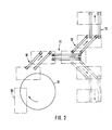
- a paper sack 30 is rotated in a schematically indicated turning station 31 and, in the rotated position, fed to a group 1 of two pairs of conveyor belts 1a and 1b.
- the conveyor belts of the conveyor belt pairs are aligned on the top and bottom and are of the same length. They grip the paper tube section between them, with the help of the drivers 1e and 1f, which sit on the lower conveyor belt and circulate with it, for example.
- the drivers of the various conveyor belt groups each press the transported paper tube sections 30 against the upper conveyor belts rotating in the same direction above them.
- a conveyor belt group 2 is provided at the end of the conveyor belt group 1.
- This conveyor belt group in turn consists of two conveyor belts arranged parallel to one another pair 2a and 2b and also has drivers 2e, 2f, 2g and 2h, with which it grasps the paper tube section 30.
- the conveyor belt pairs 2a and 2b are offset from one another in their longitudinal direction. The offset takes place in such a way that a connecting straight line runs through the axes of rotation of the adjacent deflection rollers 2c and 2d or 2e and 2f parallel to the common axes of the deflection rollers 3c and 3d of the adjacent conveyor belt group 3.
- the connecting straight line mentioned runs perpendicular to the common axis of the deflection rollers 1c and 1d of the conveyor belt group 1.
- the paper tube section 30 or the paper tube is taken over by the conveyor belt groups 3a and 3b at the rear end of group 2 and further conveyed to the right according to FIG. It is possible for each conveyor belt group to have only one driver.
- FIG. 2 shows an example arrangement of other conveyor belt groups 10, 11, 12 and 13, which can also be arranged in the broken line.
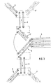
- FIG. 3 shows a further embodiment, which has conveyor belt groups 4, 5, 6 and 7.
- the conveyor belt group 5 can be designed to be pivotable horizontally into the pivoting position 5 '. Groups 8 and 9 join there. Alternatively, the conveyor belt groups 7 'and 9' are provided.
- the conveyor belt group 4 has more than two conveyor belts.
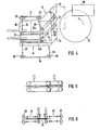
- the embodiment according to FIG. 4 shows a schematically represented turning station 31, which transfers a paper tube section or paper tube 30 to the group 15.
- the group 15 consists of two conveyor belt pairs 15a and 15b, which are arranged at an angle a to the conveyor belt pairs 14a and 14b of the group 14.
- the conveyor belt pairs run between a plurality of support plates 32, 33, 34 and 35.
- both conveyor belt groups 14 and 15 takes place together with the aid of drive belts 16 and 17, which couple the drive wheels 18 and 19 on the one hand and 20 and 21 in a fixed ratio to one another.
- the drive belts 16 and 17 can be toothed belts.
- the drive wheels 18, 19, 20 and 21 are in engagement with corresponding drive wheels underneath.
- Both the upper and the lower drive wheels are connected via universal joint shafts 22, 23, 24 and 25 to the respective drive rollers for the conveyor belt pairs 14a, 14b and 15a, 15b.
Landscapes
- Engineering & Computer Science (AREA)
- Mechanical Engineering (AREA)
- Structure Of Belt Conveyors (AREA)
- Delivering By Means Of Belts And Rollers (AREA)
- Making Paper Articles (AREA)
- Paper (AREA)
Claims (7)
Applications Claiming Priority (2)
| Application Number | Priority Date | Filing Date | Title |
|---|---|---|---|
| DE19828216238U DE8216238U1 (de) | 1982-06-04 | 1982-06-04 | Transporteinrichtung fuer papierschlauchabschnitte |
| DE8216238U | 1982-06-04 |
Publications (3)
| Publication Number | Publication Date |
|---|---|
| EP0096323A2 EP0096323A2 (fr) | 1983-12-21 |
| EP0096323A3 EP0096323A3 (en) | 1984-02-01 |
| EP0096323B1 true EP0096323B1 (fr) | 1986-03-05 |
Family
ID=6740755
Family Applications (1)
| Application Number | Title | Priority Date | Filing Date |
|---|---|---|---|
| EP83105306A Expired EP0096323B1 (fr) | 1982-06-04 | 1983-05-28 | Dispositif de transport pour tronçons de tuyaux de papier |
Country Status (6)
| Country | Link |
|---|---|
| EP (1) | EP0096323B1 (fr) |
| DE (2) | DE8216238U1 (fr) |
| DK (1) | DK252383A (fr) |
| ES (1) | ES522961A0 (fr) |
| FI (1) | FI831942L (fr) |
| NO (1) | NO832028L (fr) |
Families Citing this family (5)
| Publication number | Priority date | Publication date | Assignee | Title |
|---|---|---|---|---|
| US4889333A (en) * | 1987-03-09 | 1989-12-26 | Gaemmerler Hagen | Conveying apparatus for paper products, in particular in stream form |
| DE3805596A1 (de) * | 1988-02-23 | 1989-08-31 | Gaemmerler Hagen | Vorrichtung zum transportieren und fuehren von flaechengebilden in kreisform |
| DE9114766U1 (de) * | 1991-11-27 | 1992-03-05 | n - p - f - e n - p - fank Maschinenhandel GmbH, 4300 Essen | Fördereinrichtung, insbesondere für eine Umreifungsmaschine für Druckschriftenstapel o.dgl. |
| FR2739845B1 (fr) * | 1995-10-16 | 1997-11-28 | Realisations Etudes Et Commerc | Dispositif de renvoi d'angle a grande vitesse pour nappes de cahiers imprimes |
| DE10020909B4 (de) | 2000-04-28 | 2004-07-22 | Koenig & Bauer Ag | Vorrichtung zur Förderung einer Vorratsrolle |
Family Cites Families (3)
| Publication number | Priority date | Publication date | Assignee | Title |
|---|---|---|---|---|
| GB1326893A (en) * | 1969-08-22 | 1973-08-15 | Surbrook L M | Folders trimmers or other machines in which printed material is handled |
| US3998136A (en) * | 1976-01-19 | 1976-12-21 | Box Innards, Inc. | High speed partition assembling method and apparatus |
| DD126257B1 (de) * | 1976-06-22 | 1981-01-28 | Guenter Thieme | Bandfoerdervorrichtung zum ausgeben und weiterfoerdern von bogen |
-
1982
- 1982-06-04 DE DE19828216238U patent/DE8216238U1/de not_active Expired
-
1983
- 1983-05-28 DE DE8383105306T patent/DE3362405D1/de not_active Expired
- 1983-05-28 EP EP83105306A patent/EP0096323B1/fr not_active Expired
- 1983-05-31 FI FI831942A patent/FI831942L/fi not_active Application Discontinuation
- 1983-06-02 DK DK252383A patent/DK252383A/da not_active Application Discontinuation
- 1983-06-03 ES ES522961A patent/ES522961A0/es active Granted
- 1983-06-03 NO NO832028A patent/NO832028L/no unknown
Also Published As
| Publication number | Publication date |
|---|---|
| EP0096323A3 (en) | 1984-02-01 |
| DK252383A (da) | 1983-12-05 |
| ES8406358A1 (es) | 1984-07-01 |
| FI831942A7 (fi) | 1983-12-05 |
| DE3362405D1 (en) | 1986-04-10 |
| FI831942A0 (fi) | 1983-05-31 |
| ES522961A0 (es) | 1984-07-01 |
| DK252383D0 (da) | 1983-06-02 |
| EP0096323A2 (fr) | 1983-12-21 |
| DE8216238U1 (de) | 1982-09-09 |
| FI831942L (fi) | 1983-12-05 |
| NO832028L (no) | 1983-12-05 |
Similar Documents
| Publication | Publication Date | Title |
|---|---|---|
| EP0038450B1 (fr) | Dispositif d'enfilage pour une presse rotative à rouleaux | |
| EP0481172B1 (fr) | Rotative d'impression pour l'impression de livres et de calandriers, avec deux dispositifs de pliage longitudinal | |
| EP0256333A2 (fr) | Dispositif de pliage | |
| EP0210633B1 (fr) | Dispositif de pliage avec assemblage avant le troisième pli | |
| DE3875047T2 (de) | Verfahren zur herstellung von teig- und fettblaettchen. | |
| EP1137588B1 (fr) | Dispositif d'amenee de bandes de matiere pour appareil de pliage | |
| DE19509947C2 (de) | Falzapparat für eine Rotationsdruckmaschine | |
| EP3046839B1 (fr) | Dispositif de fabrication d'unités d'emballage | |
| DE2823247C2 (de) | Einrichtung zur Umlenkung eines aus bogenförmigen Produkten bestehenden Produktstroms | |
| DE3038058A1 (de) | Einrichtung zum aufstapeln von flachen gegenstaenden,insbesondere von faltschachtel-zuschnitten | |
| DE3315490A1 (de) | Verfahren und vorrichtung zum stapeln von druckbogen o.dgl. | |
| DE2916270C2 (de) | Bogenfördervorrichtung | |
| DE2731575C3 (de) | Verfahren und Anordnung zum wahlweisen seitlichen Verschieben von in einer vorgegebenen Richtung zu fördernden Blättern | |
| EP0096323B1 (fr) | Dispositif de transport pour tronçons de tuyaux de papier | |
| EP1275499A2 (fr) | Procédé d'actionnement d'une unité, par exemple une plieuse de presse rotative | |
| CH655076A5 (de) | Vorrichtung zum stapeln von druckbogen. | |
| CH687245A5 (de) | Einrichtung zum Foerdern und Trennen von gefalteten Druckprodukten. | |
| DE19610900A1 (de) | Falzapparat mit einem heftebildenden Zusatzmodul | |
| EP0254095B1 (fr) | Dispositif de pliage longitudinal dans un appareil de pliage | |
| DE19927920A1 (de) | Schneideinrichtung im Falzapparat einer Rotationsdruckmaschine und Falzapparat mit einer solchen Schneideinrichtung | |
| EP0091582B1 (fr) | Dispositif pour étirer des piles de produits pliés mutuellement déplacées transversalement par rapport à la direction de transport | |
| DE20321326U1 (de) | Vorrichtung zum Führen einer teilbreiten Bahn und eine Bearbeitungsmaschine mit dieser Vorrichtung | |
| EP0765247A1 (fr) | Procede et dispositif pour traiter des produits imprimes | |
| DE3429172A1 (de) | Vorrichtung zum laengsfalzen uebereinanderliegender bahnen | |
| EP1112952B1 (fr) | Dispositif pour plier en continu de matériau plat |
Legal Events
| Date | Code | Title | Description |
|---|---|---|---|
| PUAI | Public reference made under article 153(3) epc to a published international application that has entered the european phase |
Free format text: ORIGINAL CODE: 0009012 |
|
| PUAL | Search report despatched |
Free format text: ORIGINAL CODE: 0009013 |
|
| AK | Designated contracting states |
Designated state(s): BE DE FR GB IT LU NL SE |
|
| AK | Designated contracting states |
Designated state(s): BE DE FR GB IT LU NL SE |
|
| 17P | Request for examination filed |
Effective date: 19831212 |
|
| GRAA | (expected) grant |
Free format text: ORIGINAL CODE: 0009210 |
|
| RBV | Designated contracting states (corrected) |
Designated state(s): DE FR GB IT |
|
| AK | Designated contracting states |
Kind code of ref document: B1 Designated state(s): DE FR GB IT |
|
| REF | Corresponds to: |
Ref document number: 3362405 Country of ref document: DE Date of ref document: 19860410 |
|
| ET | Fr: translation filed | ||
| ITF | It: translation for a ep patent filed | ||
| PLBE | No opposition filed within time limit |
Free format text: ORIGINAL CODE: 0009261 |
|
| STAA | Information on the status of an ep patent application or granted ep patent |
Free format text: STATUS: NO OPPOSITION FILED WITHIN TIME LIMIT |
|
| 26N | No opposition filed | ||
| PG25 | Lapsed in a contracting state [announced via postgrant information from national office to epo] |
Ref country code: GB Effective date: 19880528 |
|
| GBPC | Gb: european patent ceased through non-payment of renewal fee | ||
| PGFP | Annual fee paid to national office [announced via postgrant information from national office to epo] |
Ref country code: DE Payment date: 19890414 Year of fee payment: 7 |
|
| PG25 | Lapsed in a contracting state [announced via postgrant information from national office to epo] |
Ref country code: FR Free format text: LAPSE BECAUSE OF NON-PAYMENT OF DUE FEES Effective date: 19900131 |
|
| REG | Reference to a national code |
Ref country code: FR Ref legal event code: ST |
|
| PG25 | Lapsed in a contracting state [announced via postgrant information from national office to epo] |
Ref country code: DE Effective date: 19910201 |