EP0095602A1 - Dispositif pour le transport de produits planes de papier alimentés en continu - Google Patents
Dispositif pour le transport de produits planes de papier alimentés en continu Download PDFInfo
- Publication number
- EP0095602A1 EP0095602A1 EP83104527A EP83104527A EP0095602A1 EP 0095602 A1 EP0095602 A1 EP 0095602A1 EP 83104527 A EP83104527 A EP 83104527A EP 83104527 A EP83104527 A EP 83104527A EP 0095602 A1 EP0095602 A1 EP 0095602A1
- Authority
- EP
- European Patent Office
- Prior art keywords
- paper products
- grippers
- products
- traction element
- jaws
- Prior art date
- Legal status (The legal status is an assumption and is not a legal conclusion. Google has not performed a legal analysis and makes no representation as to the accuracy of the status listed.)
- Granted
Links
Images
Classifications
-
- B—PERFORMING OPERATIONS; TRANSPORTING
- B65—CONVEYING; PACKING; STORING; HANDLING THIN OR FILAMENTARY MATERIAL
- B65H—HANDLING THIN OR FILAMENTARY MATERIAL, e.g. SHEETS, WEBS, CABLES
- B65H29/00—Delivering or advancing articles from machines; Advancing articles to or into piles
- B65H29/66—Advancing articles in overlapping streams
- B65H29/669—Advancing articles in overlapping streams ending an overlapping stream
-
- B—PERFORMING OPERATIONS; TRANSPORTING
- B65—CONVEYING; PACKING; STORING; HANDLING THIN OR FILAMENTARY MATERIAL
- B65H—HANDLING THIN OR FILAMENTARY MATERIAL, e.g. SHEETS, WEBS, CABLES
- B65H29/00—Delivering or advancing articles from machines; Advancing articles to or into piles
- B65H29/003—Delivering or advancing articles from machines; Advancing articles to or into piles by grippers
- B65H29/005—Delivering or advancing articles from machines; Advancing articles to or into piles by grippers by chains or bands having mechanical grippers engaging the side edges of articles, e.g. newspaper conveyors
-
- B—PERFORMING OPERATIONS; TRANSPORTING
- B65—CONVEYING; PACKING; STORING; HANDLING THIN OR FILAMENTARY MATERIAL
- B65H—HANDLING THIN OR FILAMENTARY MATERIAL, e.g. SHEETS, WEBS, CABLES
- B65H2301/00—Handling processes for sheets or webs
- B65H2301/40—Type of handling process
- B65H2301/44—Moving, forwarding, guiding material
- B65H2301/447—Moving, forwarding, guiding material transferring material between transport devices
- B65H2301/4471—Grippers, e.g. moved in paths enclosing an area
- B65H2301/44712—Grippers, e.g. moved in paths enclosing an area carried by chains or bands
-
- B—PERFORMING OPERATIONS; TRANSPORTING
- B65—CONVEYING; PACKING; STORING; HANDLING THIN OR FILAMENTARY MATERIAL
- B65H—HANDLING THIN OR FILAMENTARY MATERIAL, e.g. SHEETS, WEBS, CABLES
- B65H2301/00—Handling processes for sheets or webs
- B65H2301/40—Type of handling process
- B65H2301/44—Moving, forwarding, guiding material
- B65H2301/447—Moving, forwarding, guiding material transferring material between transport devices
- B65H2301/4473—Belts, endless moving elements on which the material is in surface contact
- B65H2301/44732—Belts, endless moving elements on which the material is in surface contact transporting articles in overlapping stream
Definitions
- the invention relates to a device of the type mentioned in the preamble of claim 1.
- Such a device is previously known and one of its main advantages is that it does not need to be adapted to the format of the paper products to be transported, provided that the lateral edges of successive paper products to be gripped are somewhat aligned with one another.
- the one-sided grasping of the paper products entails that they flutter around, especially at higher transport speeds, due to the wind. be made to crumple. Therefore, in the known device, stationary guide rails are provided for both flat sides of the products along the entire conveying path. If you want to change the course of the conveyor path in this known device, then the guide rails of the known device must be adapted to the new course.
- the proposed device has the features specified in the characterizing part of patent claim 1.
- the grippers Since the essentially flat clamping surfaces of the grippers are inclined in the same direction with respect to the traction element, they also force the paper products onto a wave shape running transversely to the traction element, but the grippers only clamp either the back or the front of these shafts, so that the front or the back can be stretched or squeezed without the relative shifts mentioned.
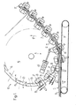
- FIGS. 1 and 2 A conveyor belt 11 with the conveying direction indicated by an arrow 12 feeds printed products 13 - here in the form of a shingled stream S - to the device 10, of which only the takeover section serving to take over the shingled stream S and the beginning of the active conveyor strand is shown in FIG. 1 .
- the device 10 has an endlessly driven traction element 14 in the direction of the arrow 12 ', which - as will be shown - is guided in a hollow rail 15 and in FIG. 1 around a deflection wheel 16 which is only shown schematically.
- the traction element 14 is equipped with grippers 17 fastened at regular intervals and laterally to these.
- Each of these grippers 17 has a fixed jaw 18 with respect to the pulling element 14, and a movable jaw 19 which, as will be shown later, is at right angles to the fixed jaw in the open position, but can first be pivoted in under the fixed jaw 18 in the course of the closing movement after that it can be adjusted (both against the action of a spring) and can be locked in the closed position.
- the clamping surface of each of the fixed jaws 18 essentially defines a plane. This plane is indicated on the left in FIG. 1 for two adjacent, fixed jaws with dashed lines 20, and is therefore opposite the traction element 14 each inclined by the angle ⁇ .
- the fixed jaws 18 of all grippers 17 are connected to one another by a flexible band 21 which is fastened to the clamping surface of the fixed jaw 18 of each gripper 17.
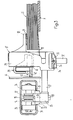
- the hollow rail 15 is a C-shaped profile which is open at the bottom, which houses the traction element 14 inside.
- This consists of a link chain 22, in which the pivot pin 23 is extended between two hinged links on both sides and carries a roller 24 at both ends.
- a bracket 27 projecting to the side is clamped by means of a clamping screw 28 and its end is anchored in the housing 29 of the gripper 17.
- the mounting block 25 partially hides a guide roller 26 in FIG. 3, which is rotatable on a line at right angles to the pin 23 and indicated by dash-dotted lines
- Axis 30 is mounted.
- the guide roller 26 cooperates with the curved edges of the legs 31 of the hollow rail 15, particularly when the hollow rail 15 is curved.
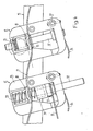
- the structure of the gripper is described below with reference to FIGS. 3 and 4.
- the fixed jaw 18 is integrally formed on the housing 29.
- the movable jaw 19, on the other hand, is anchored in a rotationally fixed manner to a shaft 32 via a clamping ring 37, which is arranged at right angles to the plane defined by the fixed jaw 18 and is mounted in the housing 29 both longitudinally displaceably and rotatably against the action of a spring 33.
- the spring 33 tends to keep the movable jaw 19 in the position shown in FIG. 4 on the left.
- a clamp bolt 34 is also articulated on the housing 29 and has a bore 35 (FIG. 3) through which the shaft 32 extends.
- the clamp bolt 34 is under the action of a compression spring 36 (Fig. 3) which tends to keep the clamp bolt pivoted downward (i.e. counterclockwise in Fig. 4).
- This arrangement allows the shaft 32 to be easily rotated and also easily moved upward from the position shown in FIG. 4, but remains locked in the upwardly displaced position.
- the clamping bolt 34 acts as a kind of "freewheel” for the longitudinal displacement of the shaft 32, which freewheel can be released by lifting the clamping bolt 34.
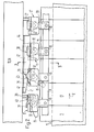
- FIG. 2 further shows that a further block 38 is anchored to the shaft 32 immediately above the clamping ring 37 anchoring the movable jaw 19 to the shaft 32.
- This block 38 carries two follower links, one of which is a nose 39 (FIG. 2), the other a roller 40 rotatably mounted on the block 38.
- FIG. 2 further shows that the nose 39 with the side edge 41 is one Backdrop 42 interacts and, when running onto this side edge 41, causes shaft 32 to rotate counterclockwise (in FIG. 2) against the action of spring 33.
- the roller 40 interacts with the upper, flat side 43 (FIG. 3) of the link 42, which - as indicated by dashed lines in FIG. 4 - forms an ascending ramp.
- the shaft 42 and thus the movable jaw 19 is raised after the rotary movement brought about by the nose 39 with the side edge 41, that is to say it is placed on the fixed jaw 18.
- the movable jaw remains locked by the clamp bolt 34.
- the jaw 19 clamps the shingled stream S from below onto the flexible band 21, which has a wave shape due to the inclination of the clamping surfaces of the jaws 18.
- the link 42 is fastened to a pivotable plate 44 which is actuated by means of an actuating element, e.g. by means of a pneumatic cylinder 45 (FIG. 1) can be pivoted back from the active position into the rest position.
- One or more delivery stations (not shown) of the facility can be located along the active strand of the traction element or in the area of a further deflection wheel, on which the active strand runs.
- a delivery station in addition to a device receiving the conveyed printed products, for example a stacking shaft or a conveyor belt, all that is needed is an organ that interacts with the clamping bars 34 in the sense, for example a backdrop or a roller, that the clamping bar 34 pivots against the action of the compression spring 36 becomes, whereupon the movable jaw 19 suddenly flips back from the position shown on the right in FIG. 4 to the position shown on the left in FIG. 4. This means that the shed flow is released.
Priority Applications (1)
| Application Number | Priority Date | Filing Date | Title |
|---|---|---|---|
| AT83104527T ATE17697T1 (de) | 1982-06-02 | 1983-05-07 | Einrichtung zum transportieren kontinuierlich anfallender, flaechiger papierprodukte. |
Applications Claiming Priority (2)
| Application Number | Priority Date | Filing Date | Title |
|---|---|---|---|
| CH3386/82 | 1982-06-02 | ||
| CH338682 | 1982-06-02 |
Publications (2)
| Publication Number | Publication Date |
|---|---|
| EP0095602A1 true EP0095602A1 (fr) | 1983-12-07 |
| EP0095602B1 EP0095602B1 (fr) | 1986-01-29 |
Family
ID=4254838
Family Applications (1)
| Application Number | Title | Priority Date | Filing Date |
|---|---|---|---|
| EP83104527A Expired EP0095602B1 (fr) | 1982-06-02 | 1983-05-07 | Dispositif pour le transport de produits planes de papier alimentés en continu |
Country Status (13)
| Country | Link |
|---|---|
| US (1) | US4512457A (fr) |
| EP (1) | EP0095602B1 (fr) |
| JP (1) | JPH0829875B2 (fr) |
| AT (1) | ATE17697T1 (fr) |
| AU (1) | AU554453B2 (fr) |
| CA (1) | CA1193625A (fr) |
| DD (1) | DD209790A5 (fr) |
| DE (1) | DE3361987D1 (fr) |
| DK (1) | DK155214C (fr) |
| FI (1) | FI72700C (fr) |
| MX (1) | MX156631A (fr) |
| NO (1) | NO153886C (fr) |
| SU (1) | SU1194264A3 (fr) |
Cited By (2)
| Publication number | Priority date | Publication date | Assignee | Title |
|---|---|---|---|---|
| US5149083A (en) * | 1990-04-11 | 1992-09-22 | Grapha-Holding Ag | Conveyor assembly with gripers for sheet-like products |
| WO1999055609A1 (fr) * | 1998-04-28 | 1999-11-04 | Ferag Ag | Procede et dispositif pour poursuivre l'acheminement d'objets plats arrivant dans un courant lamellaire |
Families Citing this family (17)
| Publication number | Priority date | Publication date | Assignee | Title |
|---|---|---|---|---|
| US4638906A (en) * | 1985-11-19 | 1987-01-27 | Harris Graphics Corporation | Conveyor assembly |
| US4746007A (en) * | 1986-02-20 | 1988-05-24 | Quipp Incorporated | Single gripper conveyor system |
| DE3861306D1 (de) * | 1987-07-21 | 1991-01-31 | Ferag Ag | Transporteur fuer flaechige erzeugnisse, insbesondere druckprodukte. |
| CH683913A5 (de) * | 1987-10-23 | 1994-06-15 | Ferag Ag | Transporteur für kontinuierlich anfallende Flächengebilde, insbesondere Druckereiprodukte. |
| DE58901208D1 (de) * | 1988-03-03 | 1992-05-27 | Ferag Ag | Verfahren und vorrichtung zum wegfoerdern von druckereiprodukten, die in einer schuppenformation zugefuehrt werden. |
| IT1228029B (it) * | 1988-12-15 | 1991-05-27 | Salvagnini Transferica S P A S | Manipolatore di fogli piani, in particolare di lamiera |
| SE9103290L (sv) * | 1991-11-07 | 1993-05-08 | Wamag Idab Ab | Foerfarande och anordning foer att oeppna en sjaelvstaengande gripare paa en griparetransportoer |
| DK0561308T3 (da) * | 1992-03-17 | 1996-12-02 | Graphic Management Assoc | Indretning med en bevægelig transportør og gribere |
| DE59505081D1 (de) * | 1994-11-18 | 1999-03-25 | Grapha Holding Ag | Verfahren zur Herstellung von klebegebundenen Büchern, Broschuren oder dgl. Produkten |
| DK0985617T3 (da) * | 1998-09-04 | 2002-12-16 | Ferag Ag | Transportindretning for i en skælformation fremkommende, fleksible, flade genstande |
| JP2002528356A (ja) * | 1998-10-26 | 2002-09-03 | フェラーク アーゲー | 印刷物の搬送方法および搬送装置 |
| ATE259751T1 (de) * | 1999-05-31 | 2004-03-15 | Ferag Ag | Verfahren und vorrichtung zum transportieren von in einer schuppenformation anfallenden gegenständen |
| DK1063187T3 (da) | 1999-06-23 | 2004-01-19 | Ferag Ag | Indretning til udtagning af flagestrømsdele fra en flagestrøm |
| US6386816B1 (en) | 1999-08-30 | 2002-05-14 | Tokyo Kikai Seisakusho, Ltd. | Printed matter transport device |
| WO2001081216A1 (fr) * | 2000-04-20 | 2001-11-01 | Ferag Ag | Dispositif permettant d"acheminer des objets plats |
| EP1834913A1 (fr) * | 2006-03-17 | 2007-09-19 | Ferag AG | Dispositif pour ramasser et convoyer des produits plats |
| US8556067B2 (en) * | 2007-11-22 | 2013-10-15 | Ferag Ag | Conveyor system and method for conveying planar products |
Citations (1)
| Publication number | Priority date | Publication date | Assignee | Title |
|---|---|---|---|---|
| CH592562A5 (fr) * | 1974-05-28 | 1977-10-31 | Ferag Ag |
Family Cites Families (5)
| Publication number | Priority date | Publication date | Assignee | Title |
|---|---|---|---|---|
| US1079218A (en) * | 1912-11-23 | 1913-11-18 | James J Curtis | Conveyer. |
| US1920715A (en) * | 1931-03-23 | 1933-08-01 | Antone Wayne Julian | Laundry flat piece spreader and carrier |
| GB752322A (en) * | 1953-12-09 | 1956-07-11 | Daverio & Cie A G | Method and device for the conveying of flat paper goods |
| CH559692A5 (fr) * | 1973-01-12 | 1975-03-14 | Ferag Ag | |
| US4424965A (en) * | 1981-06-04 | 1984-01-10 | Advance Enterprises, Inc. | High speed transport system for newspapers and the like |
-
1983
- 1983-05-07 AT AT83104527T patent/ATE17697T1/de active
- 1983-05-07 DE DE8383104527T patent/DE3361987D1/de not_active Expired
- 1983-05-07 EP EP83104527A patent/EP0095602B1/fr not_active Expired
- 1983-05-20 CA CA000428646A patent/CA1193625A/fr not_active Expired
- 1983-05-23 US US06/496,899 patent/US4512457A/en not_active Expired - Fee Related
- 1983-05-30 AU AU15063/83A patent/AU554453B2/en not_active Ceased
- 1983-05-30 FI FI831917A patent/FI72700C/fi not_active IP Right Cessation
- 1983-05-31 JP JP58096843A patent/JPH0829875B2/ja not_active Expired - Lifetime
- 1983-06-01 MX MX197499A patent/MX156631A/es unknown
- 1983-06-01 DD DD83251640A patent/DD209790A5/de not_active IP Right Cessation
- 1983-06-01 DK DK248983A patent/DK155214C/da not_active IP Right Cessation
- 1983-06-01 NO NO831978A patent/NO153886C/no unknown
- 1983-06-01 SU SU833599705A patent/SU1194264A3/ru active
Patent Citations (1)
| Publication number | Priority date | Publication date | Assignee | Title |
|---|---|---|---|---|
| CH592562A5 (fr) * | 1974-05-28 | 1977-10-31 | Ferag Ag |
Cited By (4)
| Publication number | Priority date | Publication date | Assignee | Title |
|---|---|---|---|---|
| US5149083A (en) * | 1990-04-11 | 1992-09-22 | Grapha-Holding Ag | Conveyor assembly with gripers for sheet-like products |
| WO1999055609A1 (fr) * | 1998-04-28 | 1999-11-04 | Ferag Ag | Procede et dispositif pour poursuivre l'acheminement d'objets plats arrivant dans un courant lamellaire |
| AU752572B2 (en) * | 1998-04-28 | 2002-09-26 | Ferag Ag | Method and device for further conveyance of flat objects arriving in a lamellar flow |
| AU752572C (en) * | 1998-04-28 | 2003-07-24 | Ferag Ag | Method and device for further conveyance of flat objects arriving in a lamellar flow |
Also Published As
| Publication number | Publication date |
|---|---|
| FI72700B (fi) | 1987-03-31 |
| FI831917L (fi) | 1983-12-03 |
| DE3361987D1 (en) | 1986-03-13 |
| FI831917A0 (fi) | 1983-05-30 |
| NO153886B (no) | 1986-03-03 |
| EP0095602B1 (fr) | 1986-01-29 |
| MX156631A (es) | 1988-09-20 |
| DK155214C (da) | 1989-07-17 |
| ATE17697T1 (de) | 1986-02-15 |
| US4512457A (en) | 1985-04-23 |
| CA1193625A (fr) | 1985-09-17 |
| NO153886C (no) | 1986-06-11 |
| DD209790A5 (de) | 1984-05-23 |
| DK155214B (da) | 1989-03-06 |
| AU1506383A (en) | 1983-12-08 |
| JPH0829875B2 (ja) | 1996-03-27 |
| DK248983A (da) | 1983-12-03 |
| AU554453B2 (en) | 1986-08-21 |
| FI72700C (fi) | 1987-07-10 |
| NO831978L (no) | 1983-12-05 |
| DK248983D0 (da) | 1983-06-01 |
| SU1194264A3 (ru) | 1985-11-23 |
| JPS58220045A (ja) | 1983-12-21 |
Similar Documents
| Publication | Publication Date | Title |
|---|---|---|
| EP0095602B1 (fr) | Dispositif pour le transport de produits planes de papier alimentés en continu | |
| DE1761688B2 (de) | Transporteinrichtung für in einer Schuppenformation anfallende, flächenhafte Gebilde | |
| CH660353A5 (de) | Verfahren und vorrichtung zum unterteilen eines schuppenstromes aus druckbogen in teilschuppen. | |
| CH668245A5 (de) | Einrichtung zum zusammentragen unterschiedlicher druckprodukte. | |
| EP1046599A1 (fr) | Dispositif pour transporter des articles planes | |
| EP2415700A2 (fr) | Dispositif d'orientation d'un produit plat | |
| DE2346898C2 (de) | Vorrichtung zum Aussondern eines biegeschlaffen, flachen Gegenstandes aus einer Reihe von auf einer Förderstrecke bewegten sich überlappenden Gegenständen | |
| DE3306815C2 (de) | Vorrichtung zum transportieren von in einer schuppenformation anfallenden flaechigen erzeugnissen, insbesondere druckprodukten | |
| DE3023533C2 (de) | Vorrichtung zum Ablegen von Bogen in einem Stapel | |
| DE3130945A1 (de) | "vorrichtung zum herausloesen von mittels eines foerderers gefoerderten biegsamen, flaechigen erzeugnissen, insbesondere druckprodukten, aus dem foerderstrom" | |
| EP0456978B1 (fr) | Pince pour le transport de produits, en particulier de produits plats | |
| CH638149A5 (de) | Staustation in einer faltschachtelpackmaschine. | |
| EP0564812A1 (fr) | Procédé et dispositif pour ouvrir des produits d'imprimerie pliés | |
| EP0300171B1 (fr) | Dispositif de transport pour produits plats, en particulier des produits imprimés | |
| EP0312755B1 (fr) | Convoyeur pour des produits plans amenés en continu, notamment d'imprimés | |
| DE1951598C3 (de) | Auswelchspur für eine Arbeitsvorrichtung enthaltende Fertigungsstraßen | |
| EP0218804B1 (fr) | Dispositif pour reprendre et transférer des feuilles pliées d'un dispositif de transport | |
| DE3244422A1 (de) | Schneidevorrichtung fuer bogen sowie hefte mit mindestens einem rotierenden schneidmesser und einer foerdervorrichtung | |
| DE2519420C3 (de) | Falzvorrichtung | |
| DE3300649C2 (de) | Einrichtung zum Fördern und Trennen von gefalteten Druckprodukten | |
| EP1072546B1 (fr) | Convoyeur pour assembler et traiter des produits imprimés | |
| DE2109468C2 (de) | Faltmaschine zum Umlegen der Laschen von Faltschachteln | |
| WO2001081217A1 (fr) | Dispositif pour le transport d"objets | |
| EP0207271B1 (fr) | Dispositif pour comprimer le pli d'articles imprimés transportés sur un convoyeur | |
| EP1040065B1 (fr) | Pince pour tenir des objets plans |
Legal Events
| Date | Code | Title | Description |
|---|---|---|---|
| PUAI | Public reference made under article 153(3) epc to a published international application that has entered the european phase |
Free format text: ORIGINAL CODE: 0009012 |
|
| 17P | Request for examination filed |
Effective date: 19830928 |
|
| AK | Designated contracting states |
Designated state(s): AT BE CH DE FR GB IT LI NL SE |
|
| GRAA | (expected) grant |
Free format text: ORIGINAL CODE: 0009210 |
|
| AK | Designated contracting states |
Designated state(s): AT BE CH DE FR GB IT LI NL SE |
|
| REF | Corresponds to: |
Ref document number: 17697 Country of ref document: AT Date of ref document: 19860215 Kind code of ref document: T |
|
| ET | Fr: translation filed | ||
| REF | Corresponds to: |
Ref document number: 3361987 Country of ref document: DE Date of ref document: 19860313 |
|
| ITF | It: translation for a ep patent filed |
Owner name: SAIC BREVETTI S.R.L. |
|
| PLBE | No opposition filed within time limit |
Free format text: ORIGINAL CODE: 0009261 |
|
| STAA | Information on the status of an ep patent application or granted ep patent |
Free format text: STATUS: NO OPPOSITION FILED WITHIN TIME LIMIT |
|
| 26N | No opposition filed | ||
| ITTA | It: last paid annual fee | ||
| PGFP | Annual fee paid to national office [announced via postgrant information from national office to epo] |
Ref country code: FR Payment date: 19940420 Year of fee payment: 12 |
|
| PGFP | Annual fee paid to national office [announced via postgrant information from national office to epo] |
Ref country code: NL Payment date: 19940531 Year of fee payment: 12 |
|
| EAL | Se: european patent in force in sweden |
Ref document number: 83104527.3 |
|
| PG25 | Lapsed in a contracting state [announced via postgrant information from national office to epo] |
Ref country code: NL Effective date: 19951201 |
|
| NLV4 | Nl: lapsed or anulled due to non-payment of the annual fee |
Effective date: 19951201 |
|
| PG25 | Lapsed in a contracting state [announced via postgrant information from national office to epo] |
Ref country code: FR Effective date: 19960229 |
|
| REG | Reference to a national code |
Ref country code: FR Ref legal event code: ST |
|
| REG | Reference to a national code |
Ref country code: FR Ref legal event code: ST |
|
| PGFP | Annual fee paid to national office [announced via postgrant information from national office to epo] |
Ref country code: BE Payment date: 19960422 Year of fee payment: 14 |
|
| PGFP | Annual fee paid to national office [announced via postgrant information from national office to epo] |
Ref country code: AT Payment date: 19960423 Year of fee payment: 14 |
|
| PG25 | Lapsed in a contracting state [announced via postgrant information from national office to epo] |
Ref country code: AT Effective date: 19970507 |
|
| PG25 | Lapsed in a contracting state [announced via postgrant information from national office to epo] |
Ref country code: BE Effective date: 19970531 |
|
| BERE | Be: lapsed |
Owner name: FERAG A.G. Effective date: 19970531 |
|
| PGFP | Annual fee paid to national office [announced via postgrant information from national office to epo] |
Ref country code: GB Payment date: 20010412 Year of fee payment: 19 |
|
| PGFP | Annual fee paid to national office [announced via postgrant information from national office to epo] |
Ref country code: SE Payment date: 20010503 Year of fee payment: 19 |
|
| PGFP | Annual fee paid to national office [announced via postgrant information from national office to epo] |
Ref country code: DE Payment date: 20010509 Year of fee payment: 19 |
|
| REG | Reference to a national code |
Ref country code: GB Ref legal event code: IF02 |
|
| PG25 | Lapsed in a contracting state [announced via postgrant information from national office to epo] |
Ref country code: GB Free format text: LAPSE BECAUSE OF NON-PAYMENT OF DUE FEES Effective date: 20020507 |
|
| PG25 | Lapsed in a contracting state [announced via postgrant information from national office to epo] |
Ref country code: SE Free format text: LAPSE BECAUSE OF NON-PAYMENT OF DUE FEES Effective date: 20020508 |
|
| PGFP | Annual fee paid to national office [announced via postgrant information from national office to epo] |
Ref country code: CH Payment date: 20020527 Year of fee payment: 20 |
|
| PG25 | Lapsed in a contracting state [announced via postgrant information from national office to epo] |
Ref country code: DE Free format text: LAPSE BECAUSE OF NON-PAYMENT OF DUE FEES Effective date: 20021203 |
|
| GBPC | Gb: european patent ceased through non-payment of renewal fee |
Effective date: 20020507 |
|
| EUG | Se: european patent has lapsed | ||
| PG25 | Lapsed in a contracting state [announced via postgrant information from national office to epo] |
Ref country code: LI Free format text: LAPSE BECAUSE OF EXPIRATION OF PROTECTION Effective date: 20030506 Ref country code: CH Free format text: LAPSE BECAUSE OF EXPIRATION OF PROTECTION Effective date: 20030506 |
|
| REG | Reference to a national code |
Ref country code: CH Ref legal event code: PL |