EP0095398B1 - Tranformateur électrique à circuits primaires modulaires alimentés sélectivement - Google Patents
Tranformateur électrique à circuits primaires modulaires alimentés sélectivement Download PDFInfo
- Publication number
- EP0095398B1 EP0095398B1 EP83400904A EP83400904A EP0095398B1 EP 0095398 B1 EP0095398 B1 EP 0095398B1 EP 83400904 A EP83400904 A EP 83400904A EP 83400904 A EP83400904 A EP 83400904A EP 0095398 B1 EP0095398 B1 EP 0095398B1
- Authority
- EP
- European Patent Office
- Prior art keywords
- module
- winding
- modules
- primary
- voltage
- Prior art date
- Legal status (The legal status is an assumption and is not a legal conclusion. Google has not performed a legal analysis and makes no representation as to the accuracy of the status listed.)
- Expired
Links
- 230000000694 effects Effects 0.000 claims abstract description 11
- 230000006698 induction Effects 0.000 claims abstract description 11
- 238000004804 winding Methods 0.000 claims description 96
- 230000001939 inductive effect Effects 0.000 claims description 2
- 230000003472 neutralizing effect Effects 0.000 claims description 2
- 238000006243 chemical reaction Methods 0.000 claims 1
- 230000001105 regulatory effect Effects 0.000 abstract description 3
- 238000006386 neutralization reaction Methods 0.000 abstract description 2
- 238000009877 rendering Methods 0.000 abstract 1
- 238000010586 diagram Methods 0.000 description 5
- 238000009434 installation Methods 0.000 description 4
- 238000004519 manufacturing process Methods 0.000 description 4
- 230000008901 benefit Effects 0.000 description 3
- 230000033228 biological regulation Effects 0.000 description 3
- 230000003247 decreasing effect Effects 0.000 description 3
- 230000010363 phase shift Effects 0.000 description 3
- RYGMFSIKBFXOCR-UHFFFAOYSA-N Copper Chemical compound [Cu] RYGMFSIKBFXOCR-UHFFFAOYSA-N 0.000 description 2
- 240000008042 Zea mays Species 0.000 description 2
- 238000010276 construction Methods 0.000 description 2
- 229910052802 copper Inorganic materials 0.000 description 2
- 239000010949 copper Substances 0.000 description 2
- 230000002829 reductive effect Effects 0.000 description 2
- OKTJSMMVPCPJKN-UHFFFAOYSA-N Carbon Chemical compound [C] OKTJSMMVPCPJKN-UHFFFAOYSA-N 0.000 description 1
- 230000009471 action Effects 0.000 description 1
- 230000002411 adverse Effects 0.000 description 1
- 230000005540 biological transmission Effects 0.000 description 1
- 229910052799 carbon Inorganic materials 0.000 description 1
- 210000004027 cell Anatomy 0.000 description 1
- 239000003245 coal Substances 0.000 description 1
- 238000009795 derivation Methods 0.000 description 1
- 238000011161 development Methods 0.000 description 1
- 230000018109 developmental process Effects 0.000 description 1
- 238000009713 electroplating Methods 0.000 description 1
- 238000010438 heat treatment Methods 0.000 description 1
- 230000005415 magnetization Effects 0.000 description 1
- 230000009347 mechanical transmission Effects 0.000 description 1
- 238000005272 metallurgy Methods 0.000 description 1
- 230000004048 modification Effects 0.000 description 1
- 238000012986 modification Methods 0.000 description 1
- 230000036961 partial effect Effects 0.000 description 1
- 239000002994 raw material Substances 0.000 description 1
- 230000002441 reversible effect Effects 0.000 description 1
- 238000009738 saturating Methods 0.000 description 1
- 230000006641 stabilisation Effects 0.000 description 1
- 238000011105 stabilization Methods 0.000 description 1
- 230000009466 transformation Effects 0.000 description 1
Images

Classifications
-
- H—ELECTRICITY
- H01—ELECTRIC ELEMENTS
- H01F—MAGNETS; INDUCTANCES; TRANSFORMERS; SELECTION OF MATERIALS FOR THEIR MAGNETIC PROPERTIES
- H01F29/00—Variable transformers or inductances not covered by group H01F21/00
- H01F29/02—Variable transformers or inductances not covered by group H01F21/00 with tappings on coil or winding; with provision for rearrangement or interconnection of windings
-
- H—ELECTRICITY
- H01—ELECTRIC ELEMENTS
- H01F—MAGNETS; INDUCTANCES; TRANSFORMERS; SELECTION OF MATERIALS FOR THEIR MAGNETIC PROPERTIES
- H01F38/00—Adaptations of transformers or inductances for specific applications or functions
- H01F2038/006—Adaptations of transformers or inductances for specific applications or functions matrix transformer consisting of several interconnected individual transformers working as a whole
Definitions
- the present invention relates to a variable voltage transformer.
- the secondary has several output terminals and a switch is applied selectively to one or other of these terminals to give a variable operating voltage depending on the height of the secondary to which the socket is located.
- Magnetic amplifiers or "transducers include a magnetic circuit and a choke coil, which makes it possible to obtain an adjustment without moving mechanical part, because one acts by saturating and desaturating the magnetic circuit by causing a phase shift.
- document FR-A-2406 908 which describes a regulator composed of several transformers each comprising a primary circuit, a magnetic circuit and a secondary circuit, the latter being electrically connected to the secondary of neighboring transformers.
- each primary is associated with switching means which are intended to short-circuit it when it is not in use.
- the present invention overcomes all these drawbacks as will be seen below, since a transformer according to the invention knows no power limit, operates with a pure sinusoidal regime, has a constant cosine, does not cause breakage of load and allows an adjustment of a finesse as great as is desired because the pitch of this adjustment can be practically insensitive.
- the subject of the invention is an electrical transformer intended to deliver an adjustable electrical quantity, in particular for regulation purposes, comprising several modules which have a binary progression relationship between them and which are associated with switching means making them selectively operative or inoperative for electrical transformation, each module comprising at least one primary circuit winding, characterized in that each of the primaries of each of the modules cooperates with a secondary magnetic circuit which is common to all the modules, in that the switching means are connected to neutralize the effect of the electrical induction of the respective primaries on said common secondary while retaining the magnetic activity of said primaries.
- the supply voltage and each of two terminals of the primary circuit winding of each module are interposed two electronic switches such as thyristors or transistors mounted head to tail and selectively controlled to ensure the reversal of the supply of said circuit winding primary.
- Each module comprises two primary circuit windings selectively supplied, either to ensure induction in the secondary circuit winding, or to neutralize the effect of this induction on said secondary.
- Two primary circuit windings are in opposite directions, a connector being provided to establish contact between the original voltage and one or the other of these two primary circuit windings.
- Two windings are in the same direction and in that an inverter is interposed between the terminals of only one of these windings on the one hand and the original voltage which simultaneously supplies the other winding on the other hand.
- the primary circuit winding of the first module is supplied by the two main lines of a voltage source and that the corresponding winding of the following modules is supplied at one of its ends by one of the two main lines and at its other end by a derivation from an intermediate point, notably in the middle, of the primary circuit winding of the previous module.
- the modules have a nominal voltage providing with a given current a power which is different for each module, the total of these individual powers being substantially equal to the maximum admissible power for the single secondary circuit.
- Each module comprising two magnetic circuits, one for each primary of this module, these magnetic circuits have constant lengths and widths while their thicknesses follow, from one module to another, a binary variation.
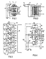
- a transformer according to the invention can comprise, as here, two modules which each comprise a single primary winding respectively 1 and 2 each associated with a magnetic circuit respectively 3 and 4, these two primary circuits being associated with a single secondary circuit winding 5 common to the two modules 1 and 2.
- Each primary winding 1 and 2 is independently connected to a nominally constant voltage source 6, for example 220 volts.
- switch respectively 7 and 8 which can occupy two positions in one of which it establishes the normal circuit (connector 8 in Figures 1 and 2) while in the other (connector 7 in Figure 1), it puts the corresponding winding in short circuit.
- the single secondary circuit 5 has a voltage which corresponds either to that which results from the winding 1 only, or to that which results from the winding 2 only is that which results from the action of the two windings 1 and 2 at the same time.
- a complete installation comprising a transformer according to the invention is equipped with a control device, possibly programmed, and acting on all the connectors to act selectively on the individual power supply of each primary module.
- a simple version consists in providing a plurality of modules all equal to each other.
- the modules have a nominal voltage which is established to provide, with a given current, a power which is different for each module.
- the total of these individual powers is substantially equal to the maximum admissible power for the single secondary circuit.
- the modules are regular decreasing fractions of the total power and are established according to a binary code.
- the denominator of each fraction is an integer power of 2 so that the most powerful module is equal to half of the total power P, or P / 2, the other halves having a power equal to respectively P / 4, P / 8, P / 16, P / 32, P / 64, etc ...
- the adjustment step, or minimum jump is equal to the smallest fraction of P provided in the transformer.
- N-1 being the fraction of the power of the last module of a given set.
- each primary module is not very bulky and that the passage from a setting at 1/127 to a setting at 1/255 requires only the addition of a extra transformer of very small dimensions.
- FIG. 3 we see an electrical diagram of a transformer according to the invention comprising six identical modules 10 to 15 and, of course, always a single secondary circuit winding 16.
- Each module comprises a coil 17 to 22 associated with an individual magnetic circuit 23 to 28.
- the AC voltage source 30 is connected to two main lines 31 and 32 to which the individual power supplies of each primary module are connected respectively 33 to 38 and 39 to 44.
- each module 10 to 15 is associated with a connector 45 to 50 respectively movable between two positions corresponding to the power supply normal or when each winding 17 to 22 is short-circuited.
- module 10 a power equal to P / 2
- module 11 an equal power to P / 4, etc ...
- the voltage of the secondary is a function of the number of modules under voltage and that it can, therefore, vary from 0 to 100 per 100 by modifying the ratio of the number of turns of the primary windings the number of turns of the secondary winding, taking the precaution of shunting the windings of the non-activated modules to give them zero impedance, this which is indeed the case since the secondary then becomes conductive.
- the single transformer according to the invention functions, in a way, like a series of transformers, the secondaries of which are all in series.
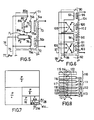
- each module comprises only one primary winding, but with the use of head-to-tail thyristors to act selectively on the induction produced by the primary winding.
- Each module includes a primary circuit winding 54 and 55 respectively and an individual magnetic circuit 56 and 57.
- Each module is supplied from a voltage source 58 connected to two main lines 59 and 60 to each of which are connected the terminals of the two windings 54 and 55.
- Each of these terminals 54a and 54b on the one hand, 55a and 55b on the other hand leads to a branch with two branches on each of which is a thyristor, which are mounted head to tail for the same branches: 61 and 62-63 and 64-65 and 66-67 and 68.
- thyristors are controlled by any known electronic means such that in the same given primary winding is sent a current, either in one direction or in the other.
- the single secondary winding 70 is the seat of a voltage which, if necessary, is added to the other voltages arising from the other modules, while in the other case no voltage is induced in the secondary winding.
- the magnetization of the magnetic circuits is permanent, whatever the effective direction of the current.
- the magnetic circuits are always supplied, but the voltage in the secondary winding is either effectively induced or zero.
- each module comprises two primary circuit windings.
- FIG. 5 shows a complete module 71 and the start of a second 72 with, as always, a single secondary circuit winding 73.
- Each module includes a magnetic circuit 74 and two coils of the same pitch, respectively 75 and 76.
- a voltage source 77 is connected to two lines 78 and 79, the latter directly leading to one of the terminals 76a of the winding 76 and to the terminal 80a of a connector 80.
- Line 78 leads to a branch with two branches, one of which leads to terminal 76b of the winding 76 and the other is connected on the one hand to terminal 75a of the winding 75 and on the other hand, to terminal 81a d a coil 81 whose pitch is opposite to that of the coil 75 and whose second terminal 81b can be connected to line 79, like terminal 75b, depending on the position of the connector 80.
- the induced voltage in the secondary winding 73 is no longer added to but subtracted from the voltage induced from the primary winding 76 so that, ultimately, the secondary winding 73 is traversed either by the nominal voltage of the module 71 or by a zero voltage for the same module 71.
- the secondary winding 73 is traversed, if necessary, by the only voltages induced by the other modules.
- FIG. 6 we can see an assembly which also includes two primary windings for each module but, here, the neutralization of each module is obtained by different means.
- Each of these two modules comprises a primary winding 93 and 94 associated with a magnetic circuit 95 and 96 and the terminals of which are permanently connected to two lines 97 and 98 supplied by a source 99.
- each of these modules comprises a second winding 100 and 101 respectively. associated with a magnetic circuit 102 and 103, all the modules corresponding, as always, to a single secondary winding 104.
- inverters 105 and 106 are interposed between the lines 97 and 98 on the one hand and the terminals of the windings 100 and 101 on the other hand.
- the voltage across the secondary winding 104 is therefore the result of an addition of the voltages of each activated module.
- This graph tends to show visually that one can easily reach an extreme fineness of adjustment since one could, whatever the power P, provide a last power module equal to P / 128 or even P / 256 or P / 512 etc ...
- This graph also shows that obtaining this finesse is done by means of an extremely compact and therefore inexpensive module whereas generally the increase in a given performance is proportionally much more complicated and costly than the performance itself.
- FIG 8 there is shown schematically a transformer according to the invention comprising four modules of the type according to which each of these comprises two primary windings and two magnetic circuits.
- each module 110,111,112 and 113 the two windings respectively 114 and 115, 116 and 117, 118 and 119,120 and 121 are equal as well as the corresponding magnetic circuits 1.22 and 123, 124 and 125, 126 and 127, 128 and 129 .
- Each module has a binary function, 0 and 1, obtained by inverting the field of one primary with respect to the other.
- FIG. 9 represents a diagram of a variant according to which a branch is connected in the middle of one of the two windings of each module and constitutes the supply of the corresponding winding of the following module.
- the module 140 is supplied with 220 Volts from the source 141 by two main lines 142 and 143. This voltage is applied to the winding 144 associated with a counterpart 145.
- a branch 146 leaves which ends at the end of the corresponding winding 147 associated with a counterpart 148 of the next module 149.
- the other end of the winding 147 is connected directly to the line 142 so that the supply voltage of winding 147 is only 110 volts.
- the winding 150 associated with the winding 151 of the module 152 is supplied with 55 Volts and so on, the secondary 153 being always unique and common to all the modules.
- the first module 140 has a power of P / 2 with a current of i / 4 for a nominal current of i.
- Module 149 has P / 4 and i / 8.
- Module 152 has P / 8 and i / 16 etc ...
- the number of turns of the primary windings is constant for all modules, regardless of their power. In this way, a standardization is achieved which leads to a saving in labor.
- control of the various modules can be obtained either by electro-mechanical means, or by electronic means.
- the winding can be obtained either independently for each of them or continuously for the two windings by giving each turn a “8” path, as shown in FIG. 10.
- a transformer according to the invention makes it possible to supply a rectifier while retaining its natural residual ripple.
- a modular transformer can be provided in accordance with the invention using mixed electro-mechanical and electronic solutions, in particular by providing thyristors for the last module only, these thyristors acting only on a tiny fraction of the sinusoid and causing a variation in power only in absolutely insignificant proportions with a very reduced distortion rate.
- the module actuation circuits are cut and closed at 0 on the sinusoid since the modification of the number of modules used has an effect on the amplitude of the sinusoid.
- the leakage surface is reduced to a minimum and is identical to that of a normal high performance transformer and in particular with the embodiments shown in Figures 1 and 8.
- the adjustment is made in an extremely fine step-by-step progression.
- Stabilization devices of all known types can be used.
- the power is unlimited.
- a transformer according to the invention has an efficiency equal to that of a normal transformer.
- the adjustment is made without any interruption of the power supply.
- the voltage variation is carried out using a step-by-step servo system which avoids setting the secondary voltage to zero when it has to be modulated.
Landscapes
- Engineering & Computer Science (AREA)
- Power Engineering (AREA)
- Dc-Dc Converters (AREA)
- Control Of Electrical Variables (AREA)
- Coils Or Transformers For Communication (AREA)
- Magnetic Treatment Devices (AREA)
- Ac-Ac Conversion (AREA)
- Coils Of Transformers For General Uses (AREA)
- Relay Circuits (AREA)
- Arrangements For Transmission Of Measured Signals (AREA)
Priority Applications (1)
| Application Number | Priority Date | Filing Date | Title |
|---|---|---|---|
| AT83400904T ATE31589T1 (de) | 1982-05-25 | 1983-05-05 | Elektrischer transformator mit aus modulen bestehenden, selektiv gespeisten primaerkreisen. |
Applications Claiming Priority (2)
| Application Number | Priority Date | Filing Date | Title |
|---|---|---|---|
| FR8208998 | 1982-05-25 | ||
| FR8208998A FR2527832A1 (fr) | 1982-05-25 | 1982-05-25 | Transformateur electrique a circuits primaires modulaires alimentes selectivement |
Publications (2)
| Publication Number | Publication Date |
|---|---|
| EP0095398A1 EP0095398A1 (fr) | 1983-11-30 |
| EP0095398B1 true EP0095398B1 (fr) | 1987-12-23 |
Family
ID=9274274
Family Applications (1)
| Application Number | Title | Priority Date | Filing Date |
|---|---|---|---|
| EP83400904A Expired EP0095398B1 (fr) | 1982-05-25 | 1983-05-05 | Tranformateur électrique à circuits primaires modulaires alimentés sélectivement |
Country Status (6)
| Country | Link |
|---|---|
| US (1) | US4678986A (enExample) |
| EP (1) | EP0095398B1 (enExample) |
| JP (1) | JPS58213409A (enExample) |
| AT (1) | ATE31589T1 (enExample) |
| DE (1) | DE3375052D1 (enExample) |
| FR (1) | FR2527832A1 (enExample) |
Families Citing this family (21)
| Publication number | Priority date | Publication date | Assignee | Title |
|---|---|---|---|---|
| US4837497A (en) * | 1987-12-29 | 1989-06-06 | Gregory Leibovich | Variable transformer, reactor and method of their control |
| US5177460A (en) * | 1990-01-04 | 1993-01-05 | Dhyanchand P John | Summing transformer for star-delta inverter having a single secondary winding for each group of primary windings |
| JPH05128324A (ja) * | 1991-11-07 | 1993-05-25 | Mitsubishi Electric Corp | 非接触カード、非接触カード用端末機及び非接触伝送システム |
| US5355296A (en) * | 1992-12-10 | 1994-10-11 | Sundstrand Corporation | Switching converter and summing transformer for use therein |
| GB2284939A (en) * | 1993-08-15 | 1995-06-21 | Aziz Fawzy Mekaiel Fanouse | Voltage regulating transformer |
| JP3416809B2 (ja) * | 1994-05-27 | 2003-06-16 | 成勲 井本 | 電気調整器 |
| US6340851B1 (en) | 1998-03-23 | 2002-01-22 | Electric Boat Corporation | Modular transformer arrangement for use with multi-level power converter |
| US6212430B1 (en) | 1999-05-03 | 2001-04-03 | Abiomed, Inc. | Electromagnetic field source with detection of position of secondary coil in relation to multiple primary coils |
| US6664881B1 (en) | 1999-11-30 | 2003-12-16 | Ameritherm, Inc. | Efficient, low leakage inductance, multi-tap, RF transformer and method of making same |
| US6806803B2 (en) * | 2002-12-06 | 2004-10-19 | Square D Company | Transformer winding |
| US6867987B2 (en) * | 2003-06-13 | 2005-03-15 | Ballard Power Systems Corporation | Multilevel inverter control schemes |
| KR101432047B1 (ko) * | 2007-09-20 | 2014-08-20 | 삼성전자주식회사 | 디지털-아날로그 컨버터 |
| CN101692392B (zh) * | 2009-09-08 | 2011-05-11 | 武汉泰普变压器开关有限公司 | 一种变压器用无励磁笼形正反调压分接开关 |
| US9002469B2 (en) | 2010-12-20 | 2015-04-07 | Abiomed, Inc. | Transcutaneous energy transfer system with multiple secondary coils |
| EP4112115A1 (en) | 2010-12-20 | 2023-01-04 | Abiomed, Inc. | Method and apparatus for accurately tracking available charge in a transcutaneous energy transfer system |
| US8766788B2 (en) | 2010-12-20 | 2014-07-01 | Abiomed, Inc. | Transcutaneous energy transfer system with vibration inducing warning circuitry |
| US8620447B2 (en) | 2011-04-14 | 2013-12-31 | Abiomed Inc. | Transcutaneous energy transfer coil with integrated radio frequency antenna |
| US9002468B2 (en) | 2011-12-16 | 2015-04-07 | Abiomed, Inc. | Automatic power regulation for transcutaneous energy transfer charging system |
| US9564266B2 (en) | 2014-10-31 | 2017-02-07 | Raytheon Company | Power converter magnetics assembly |
| US9730366B2 (en) | 2015-02-10 | 2017-08-08 | Raytheon Company | Electromagnetic interference suppressing shield |
| US10270356B2 (en) | 2016-08-09 | 2019-04-23 | Raytheon Company | High voltage high frequency power converter |
Family Cites Families (9)
| Publication number | Priority date | Publication date | Assignee | Title |
|---|---|---|---|---|
| NL278413A (enExample) * | 1961-05-15 | |||
| FR1422650A (fr) * | 1965-01-26 | 1965-12-24 | Dispositif pour le branchement d'éléments électriques, tels que résistance, capacité, self ou autre, ainsi que les ensembles pourvus d'un dispositif de branchement,conforme à l'invention | |
| JPS50497Y1 (enExample) * | 1970-08-13 | 1975-01-09 | ||
| FR2155839B1 (enExample) * | 1971-10-08 | 1975-04-18 | Alsthom Cgee | |
| FR2179507B1 (enExample) * | 1972-04-10 | 1975-03-21 | Drusch Gaston | |
| JPS5232625B2 (enExample) * | 1973-03-29 | 1977-08-23 | ||
| US4011499A (en) * | 1976-02-11 | 1977-03-08 | The Bendix Corporation | Low loss a.c. voltage regulator |
| FR2406908A1 (fr) * | 1977-10-19 | 1979-05-18 | Sirven Pierre | Dispositif de regulation du courant alternatif par commutation electronique d'enroulements de transformateurs |
| GB2063572A (en) * | 1979-11-06 | 1981-06-03 | Westinghouse Electric Corp | Tap changer for electrical inductive apparatus |
-
1982
- 1982-05-25 FR FR8208998A patent/FR2527832A1/fr active Granted
-
1983
- 1983-05-05 AT AT83400904T patent/ATE31589T1/de not_active IP Right Cessation
- 1983-05-05 DE DE8383400904T patent/DE3375052D1/de not_active Expired
- 1983-05-05 EP EP83400904A patent/EP0095398B1/fr not_active Expired
- 1983-05-24 JP JP58090116A patent/JPS58213409A/ja active Pending
-
1986
- 1986-04-24 US US06/856,449 patent/US4678986A/en not_active Expired - Fee Related
Also Published As
| Publication number | Publication date |
|---|---|
| FR2527832B1 (enExample) | 1984-11-23 |
| FR2527832A1 (fr) | 1983-12-02 |
| JPS58213409A (ja) | 1983-12-12 |
| EP0095398A1 (fr) | 1983-11-30 |
| DE3375052D1 (en) | 1988-02-04 |
| US4678986A (en) | 1987-07-07 |
| ATE31589T1 (de) | 1988-01-15 |
Similar Documents
| Publication | Publication Date | Title |
|---|---|---|
| EP0095398B1 (fr) | Tranformateur électrique à circuits primaires modulaires alimentés sélectivement | |
| FR2471702A1 (fr) | Circuit bipolaire et a effet de champ a autocontrole de la commutation | |
| FR2584858A1 (fr) | Interrupteur de circuit sans formation d'arc | |
| FR2541531A1 (fr) | Procede pour creer un courant alternatif a partir d'un courant continu | |
| CH688952B5 (fr) | Circuit d'alimentation pour une feuille électroluminescente. | |
| FR2575324A1 (fr) | Dispositif de commutation de courant electrique pouvant fonctionner de maniere synchrone, permettant de commuter des circuits multiples et/ou de reduire la resistance de contact | |
| CH648708A5 (fr) | Dispositif d'alimentation de courant continu a tension reglable comprenant un transformateur variable. | |
| EP1450474B1 (fr) | Convertisseur en transfert direct d'énergie | |
| FR2547104A1 (fr) | Transformateur de tension de haute precision | |
| EP0147306A2 (fr) | Amplificateur de puissance linéaire | |
| EP0032087A2 (fr) | Plaquette de résistances en ligne à très faible pas | |
| CA2455352C (fr) | Dispositif de conversion d'energie | |
| EP0136225B1 (fr) | Dispositif d'alimentation en énergie électrique pour générateur d'ozone | |
| EP1022855B1 (fr) | Procédé et dispositif de commande d'un circuit de déviation verticale d'un spot balayant un écran, en particulier pour télé viseur ou moniteur informatique | |
| EP0645886B1 (fr) | Générateur d'allumage haute énergie notamment pour turbine à gaz | |
| EP0032335A1 (fr) | Générateur de signaux électriques à puissance élevée | |
| FR2559320A1 (fr) | Montage pour la regulation et la transformation de la tension, en particulier d'un generateur solaire | |
| FR2735919A1 (fr) | Dispositif d'alimentation d'un moteur a reluctance variable | |
| WO2021259649A1 (fr) | Gradateur électronique | |
| FR2500232A1 (fr) | Convertisseur continu-continu regule par reaction | |
| FR2731120A1 (fr) | Procede de commande pour courant electrique bidirectionnel et onduleur de tension a commutation douce | |
| CH456745A (fr) | Dispositif de réglage pour moteur électrique à collecteur | |
| CH477128A (fr) | Circuit générateur d'impulsions | |
| EP0356294A1 (fr) | Procédé en vue de réduire les signaux perturbateurs entre au moins deux éléments interconnectés | |
| BE653121A (enExample) |
Legal Events
| Date | Code | Title | Description |
|---|---|---|---|
| PUAI | Public reference made under article 153(3) epc to a published international application that has entered the european phase |
Free format text: ORIGINAL CODE: 0009012 |
|
| AK | Designated contracting states |
Designated state(s): AT BE CH DE GB IT LI LU NL SE |
|
| 17P | Request for examination filed |
Effective date: 19840526 |
|
| GRAA | (expected) grant |
Free format text: ORIGINAL CODE: 0009210 |
|
| AK | Designated contracting states |
Kind code of ref document: B1 Designated state(s): AT BE CH DE GB IT LI LU NL SE |
|
| PG25 | Lapsed in a contracting state [announced via postgrant information from national office to epo] |
Ref country code: NL Effective date: 19871223 Ref country code: AT Effective date: 19871223 |
|
| REF | Corresponds to: |
Ref document number: 31589 Country of ref document: AT Date of ref document: 19880115 Kind code of ref document: T |
|
| PG25 | Lapsed in a contracting state [announced via postgrant information from national office to epo] |
Ref country code: SE Effective date: 19871231 |
|
| ITF | It: translation for a ep patent filed | ||
| REF | Corresponds to: |
Ref document number: 3375052 Country of ref document: DE Date of ref document: 19880204 |
|
| GBT | Gb: translation of ep patent filed (gb section 77(6)(a)/1977) | ||
| PG25 | Lapsed in a contracting state [announced via postgrant information from national office to epo] |
Ref country code: GB Effective date: 19880505 |
|
| NLV1 | Nl: lapsed or annulled due to failure to fulfill the requirements of art. 29p and 29m of the patents act | ||
| PG25 | Lapsed in a contracting state [announced via postgrant information from national office to epo] |
Ref country code: LU Free format text: LAPSE BECAUSE OF NON-PAYMENT OF DUE FEES Effective date: 19880531 Ref country code: LI Effective date: 19880531 Ref country code: CH Effective date: 19880531 |
|
| PLBE | No opposition filed within time limit |
Free format text: ORIGINAL CODE: 0009261 |
|
| STAA | Information on the status of an ep patent application or granted ep patent |
Free format text: STATUS: NO OPPOSITION FILED WITHIN TIME LIMIT |
|
| BERE | Be: lapsed |
Owner name: BARTHELEMY LOUIS Effective date: 19880531 |
|
| 26N | No opposition filed | ||
| REG | Reference to a national code |
Ref country code: CH Ref legal event code: PL |
|
| GBPC | Gb: european patent ceased through non-payment of renewal fee | ||
| PG25 | Lapsed in a contracting state [announced via postgrant information from national office to epo] |
Ref country code: DE Effective date: 19890201 |
|
| PG25 | Lapsed in a contracting state [announced via postgrant information from national office to epo] |
Ref country code: BE Effective date: 19890531 |