EP0095398B1 - Electric transformer with modular, selectively fed primary circuits - Google Patents
Electric transformer with modular, selectively fed primary circuits Download PDFInfo
- Publication number
- EP0095398B1 EP0095398B1 EP83400904A EP83400904A EP0095398B1 EP 0095398 B1 EP0095398 B1 EP 0095398B1 EP 83400904 A EP83400904 A EP 83400904A EP 83400904 A EP83400904 A EP 83400904A EP 0095398 B1 EP0095398 B1 EP 0095398B1
- Authority
- EP
- European Patent Office
- Prior art keywords
- module
- winding
- modules
- primary
- voltage
- Prior art date
- Legal status (The legal status is an assumption and is not a legal conclusion. Google has not performed a legal analysis and makes no representation as to the accuracy of the status listed.)
- Expired
Links
Images

Classifications
-
- H—ELECTRICITY
- H01—ELECTRIC ELEMENTS
- H01F—MAGNETS; INDUCTANCES; TRANSFORMERS; SELECTION OF MATERIALS FOR THEIR MAGNETIC PROPERTIES
- H01F29/00—Variable transformers or inductances not covered by group H01F21/00
- H01F29/02—Variable transformers or inductances not covered by group H01F21/00 with tappings on coil or winding; with provision for rearrangement or interconnection of windings
-
- H—ELECTRICITY
- H01—ELECTRIC ELEMENTS
- H01F—MAGNETS; INDUCTANCES; TRANSFORMERS; SELECTION OF MATERIALS FOR THEIR MAGNETIC PROPERTIES
- H01F38/00—Adaptations of transformers or inductances for specific applications or functions
- H01F2038/006—Adaptations of transformers or inductances for specific applications or functions matrix transformer consisting of several interconnected individual transformers working as a whole
Definitions
- the present invention relates to a variable voltage transformer.
- the secondary has several output terminals and a switch is applied selectively to one or other of these terminals to give a variable operating voltage depending on the height of the secondary to which the socket is located.
- Magnetic amplifiers or "transducers include a magnetic circuit and a choke coil, which makes it possible to obtain an adjustment without moving mechanical part, because one acts by saturating and desaturating the magnetic circuit by causing a phase shift.
- document FR-A-2406 908 which describes a regulator composed of several transformers each comprising a primary circuit, a magnetic circuit and a secondary circuit, the latter being electrically connected to the secondary of neighboring transformers.
- each primary is associated with switching means which are intended to short-circuit it when it is not in use.
- the present invention overcomes all these drawbacks as will be seen below, since a transformer according to the invention knows no power limit, operates with a pure sinusoidal regime, has a constant cosine, does not cause breakage of load and allows an adjustment of a finesse as great as is desired because the pitch of this adjustment can be practically insensitive.
- the subject of the invention is an electrical transformer intended to deliver an adjustable electrical quantity, in particular for regulation purposes, comprising several modules which have a binary progression relationship between them and which are associated with switching means making them selectively operative or inoperative for electrical transformation, each module comprising at least one primary circuit winding, characterized in that each of the primaries of each of the modules cooperates with a secondary magnetic circuit which is common to all the modules, in that the switching means are connected to neutralize the effect of the electrical induction of the respective primaries on said common secondary while retaining the magnetic activity of said primaries.
- the supply voltage and each of two terminals of the primary circuit winding of each module are interposed two electronic switches such as thyristors or transistors mounted head to tail and selectively controlled to ensure the reversal of the supply of said circuit winding primary.
- Each module comprises two primary circuit windings selectively supplied, either to ensure induction in the secondary circuit winding, or to neutralize the effect of this induction on said secondary.
- Two primary circuit windings are in opposite directions, a connector being provided to establish contact between the original voltage and one or the other of these two primary circuit windings.
- Two windings are in the same direction and in that an inverter is interposed between the terminals of only one of these windings on the one hand and the original voltage which simultaneously supplies the other winding on the other hand.
- the primary circuit winding of the first module is supplied by the two main lines of a voltage source and that the corresponding winding of the following modules is supplied at one of its ends by one of the two main lines and at its other end by a derivation from an intermediate point, notably in the middle, of the primary circuit winding of the previous module.
- the modules have a nominal voltage providing with a given current a power which is different for each module, the total of these individual powers being substantially equal to the maximum admissible power for the single secondary circuit.
- Each module comprising two magnetic circuits, one for each primary of this module, these magnetic circuits have constant lengths and widths while their thicknesses follow, from one module to another, a binary variation.
- a transformer according to the invention can comprise, as here, two modules which each comprise a single primary winding respectively 1 and 2 each associated with a magnetic circuit respectively 3 and 4, these two primary circuits being associated with a single secondary circuit winding 5 common to the two modules 1 and 2.
- Each primary winding 1 and 2 is independently connected to a nominally constant voltage source 6, for example 220 volts.
- switch respectively 7 and 8 which can occupy two positions in one of which it establishes the normal circuit (connector 8 in Figures 1 and 2) while in the other (connector 7 in Figure 1), it puts the corresponding winding in short circuit.
- the single secondary circuit 5 has a voltage which corresponds either to that which results from the winding 1 only, or to that which results from the winding 2 only is that which results from the action of the two windings 1 and 2 at the same time.
- a complete installation comprising a transformer according to the invention is equipped with a control device, possibly programmed, and acting on all the connectors to act selectively on the individual power supply of each primary module.
- a simple version consists in providing a plurality of modules all equal to each other.
- the modules have a nominal voltage which is established to provide, with a given current, a power which is different for each module.
- the total of these individual powers is substantially equal to the maximum admissible power for the single secondary circuit.
- the modules are regular decreasing fractions of the total power and are established according to a binary code.
- the denominator of each fraction is an integer power of 2 so that the most powerful module is equal to half of the total power P, or P / 2, the other halves having a power equal to respectively P / 4, P / 8, P / 16, P / 32, P / 64, etc ...
- the adjustment step, or minimum jump is equal to the smallest fraction of P provided in the transformer.
- N-1 being the fraction of the power of the last module of a given set.
- each primary module is not very bulky and that the passage from a setting at 1/127 to a setting at 1/255 requires only the addition of a extra transformer of very small dimensions.
- FIG. 3 we see an electrical diagram of a transformer according to the invention comprising six identical modules 10 to 15 and, of course, always a single secondary circuit winding 16.
- Each module comprises a coil 17 to 22 associated with an individual magnetic circuit 23 to 28.
- the AC voltage source 30 is connected to two main lines 31 and 32 to which the individual power supplies of each primary module are connected respectively 33 to 38 and 39 to 44.
- each module 10 to 15 is associated with a connector 45 to 50 respectively movable between two positions corresponding to the power supply normal or when each winding 17 to 22 is short-circuited.
- module 10 a power equal to P / 2
- module 11 an equal power to P / 4, etc ...
- the voltage of the secondary is a function of the number of modules under voltage and that it can, therefore, vary from 0 to 100 per 100 by modifying the ratio of the number of turns of the primary windings the number of turns of the secondary winding, taking the precaution of shunting the windings of the non-activated modules to give them zero impedance, this which is indeed the case since the secondary then becomes conductive.
- the single transformer according to the invention functions, in a way, like a series of transformers, the secondaries of which are all in series.
- each module comprises only one primary winding, but with the use of head-to-tail thyristors to act selectively on the induction produced by the primary winding.
- Each module includes a primary circuit winding 54 and 55 respectively and an individual magnetic circuit 56 and 57.
- Each module is supplied from a voltage source 58 connected to two main lines 59 and 60 to each of which are connected the terminals of the two windings 54 and 55.
- Each of these terminals 54a and 54b on the one hand, 55a and 55b on the other hand leads to a branch with two branches on each of which is a thyristor, which are mounted head to tail for the same branches: 61 and 62-63 and 64-65 and 66-67 and 68.
- thyristors are controlled by any known electronic means such that in the same given primary winding is sent a current, either in one direction or in the other.
- the single secondary winding 70 is the seat of a voltage which, if necessary, is added to the other voltages arising from the other modules, while in the other case no voltage is induced in the secondary winding.
- the magnetization of the magnetic circuits is permanent, whatever the effective direction of the current.
- the magnetic circuits are always supplied, but the voltage in the secondary winding is either effectively induced or zero.
- each module comprises two primary circuit windings.
- FIG. 5 shows a complete module 71 and the start of a second 72 with, as always, a single secondary circuit winding 73.
- Each module includes a magnetic circuit 74 and two coils of the same pitch, respectively 75 and 76.
- a voltage source 77 is connected to two lines 78 and 79, the latter directly leading to one of the terminals 76a of the winding 76 and to the terminal 80a of a connector 80.
- Line 78 leads to a branch with two branches, one of which leads to terminal 76b of the winding 76 and the other is connected on the one hand to terminal 75a of the winding 75 and on the other hand, to terminal 81a d a coil 81 whose pitch is opposite to that of the coil 75 and whose second terminal 81b can be connected to line 79, like terminal 75b, depending on the position of the connector 80.
- the induced voltage in the secondary winding 73 is no longer added to but subtracted from the voltage induced from the primary winding 76 so that, ultimately, the secondary winding 73 is traversed either by the nominal voltage of the module 71 or by a zero voltage for the same module 71.
- the secondary winding 73 is traversed, if necessary, by the only voltages induced by the other modules.
- FIG. 6 we can see an assembly which also includes two primary windings for each module but, here, the neutralization of each module is obtained by different means.
- Each of these two modules comprises a primary winding 93 and 94 associated with a magnetic circuit 95 and 96 and the terminals of which are permanently connected to two lines 97 and 98 supplied by a source 99.
- each of these modules comprises a second winding 100 and 101 respectively. associated with a magnetic circuit 102 and 103, all the modules corresponding, as always, to a single secondary winding 104.
- inverters 105 and 106 are interposed between the lines 97 and 98 on the one hand and the terminals of the windings 100 and 101 on the other hand.
- the voltage across the secondary winding 104 is therefore the result of an addition of the voltages of each activated module.
- This graph tends to show visually that one can easily reach an extreme fineness of adjustment since one could, whatever the power P, provide a last power module equal to P / 128 or even P / 256 or P / 512 etc ...
- This graph also shows that obtaining this finesse is done by means of an extremely compact and therefore inexpensive module whereas generally the increase in a given performance is proportionally much more complicated and costly than the performance itself.
- FIG 8 there is shown schematically a transformer according to the invention comprising four modules of the type according to which each of these comprises two primary windings and two magnetic circuits.
- each module 110,111,112 and 113 the two windings respectively 114 and 115, 116 and 117, 118 and 119,120 and 121 are equal as well as the corresponding magnetic circuits 1.22 and 123, 124 and 125, 126 and 127, 128 and 129 .
- Each module has a binary function, 0 and 1, obtained by inverting the field of one primary with respect to the other.
- FIG. 9 represents a diagram of a variant according to which a branch is connected in the middle of one of the two windings of each module and constitutes the supply of the corresponding winding of the following module.
- the module 140 is supplied with 220 Volts from the source 141 by two main lines 142 and 143. This voltage is applied to the winding 144 associated with a counterpart 145.
- a branch 146 leaves which ends at the end of the corresponding winding 147 associated with a counterpart 148 of the next module 149.
- the other end of the winding 147 is connected directly to the line 142 so that the supply voltage of winding 147 is only 110 volts.
- the winding 150 associated with the winding 151 of the module 152 is supplied with 55 Volts and so on, the secondary 153 being always unique and common to all the modules.
- the first module 140 has a power of P / 2 with a current of i / 4 for a nominal current of i.
- Module 149 has P / 4 and i / 8.
- Module 152 has P / 8 and i / 16 etc ...
- the number of turns of the primary windings is constant for all modules, regardless of their power. In this way, a standardization is achieved which leads to a saving in labor.
- control of the various modules can be obtained either by electro-mechanical means, or by electronic means.
- the winding can be obtained either independently for each of them or continuously for the two windings by giving each turn a “8” path, as shown in FIG. 10.
- a transformer according to the invention makes it possible to supply a rectifier while retaining its natural residual ripple.
- a modular transformer can be provided in accordance with the invention using mixed electro-mechanical and electronic solutions, in particular by providing thyristors for the last module only, these thyristors acting only on a tiny fraction of the sinusoid and causing a variation in power only in absolutely insignificant proportions with a very reduced distortion rate.
- the module actuation circuits are cut and closed at 0 on the sinusoid since the modification of the number of modules used has an effect on the amplitude of the sinusoid.
- the leakage surface is reduced to a minimum and is identical to that of a normal high performance transformer and in particular with the embodiments shown in Figures 1 and 8.
- the adjustment is made in an extremely fine step-by-step progression.
- Stabilization devices of all known types can be used.
- the power is unlimited.
- a transformer according to the invention has an efficiency equal to that of a normal transformer.
- the adjustment is made without any interruption of the power supply.
- the voltage variation is carried out using a step-by-step servo system which avoids setting the secondary voltage to zero when it has to be modulated.
Landscapes
- Engineering & Computer Science (AREA)
- Power Engineering (AREA)
- Dc-Dc Converters (AREA)
- Coils Or Transformers For Communication (AREA)
- Control Of Electrical Variables (AREA)
- Relay Circuits (AREA)
- Arrangements For Transmission Of Measured Signals (AREA)
- Ac-Ac Conversion (AREA)
- Magnetic Treatment Devices (AREA)
- Coils Of Transformers For General Uses (AREA)
Abstract
Description
La présente invention concerne un transformateur à tension variable.The present invention relates to a variable voltage transformer.
On sait que ce genre de transformateur tend à résoudre le problème qui consiste à faire varier une tension de sortie à partir d'une tension d'entrée nominale constante.We know that this kind of transformer tends to solve the problem of varying an output voltage from a constant nominal input voltage.
De tels transformateurs ont de multiples applications :
- en galvanoplastie ils permettent d'ajuster le courant en fonction du produit traité et de la surface intéressée ;
- en transmission mécanique ils entrent dans la constitution de variateurs de vitesse ;
- en métallurgie ils assurent une alimentation des fours à induction réglables.
- Jusqu'à maintenant, les transformateurs connus présentent de très nombreux inconvénients.
- in electroplating they make it possible to adjust the current according to the product treated and the surface concerned;
- in mechanical transmission they are part of the constitution of variable speed drives;
- in metallurgy they supply adjustable induction ovens.
- Up to now, known transformers have had numerous drawbacks.
Ainsi, par exemple, dans les transformateurs à prise, le secondaire comporte plusieurs bornes de sortie et un commutateur est appliqué sélectivement à l'une ou l'autre de ces bornes pour donner une tension d'utilisation variable en fonction de la hauteur du secondaire à laquelle se trouve la prise.Thus, for example, in plug-in transformers, the secondary has several output terminals and a switch is applied selectively to one or other of these terminals to give a variable operating voltage depending on the height of the secondary to which the socket is located.
Avec un tel dispositif, on se heurte à des sauts et à des ruptures de charge très graves qui obligent à une limitation extrême des puissances à réguler et, malgré cela, l'installation subit une usure rapide.With such a device, very serious jumps and breaks in load are encountered, which require extreme limitation of the powers to be regulated and, despite this, the installation undergoes rapid wear.
On connaît également les « auto-transformateurs à à curseur qui prévoient une seule prise de sortie sur le secondaire mais celle-ci est mobile et constituée par un galet en charbon.There are also known "slider auto-transformers which provide a single outlet on the secondary but this is mobile and constituted by a roller made of carbon.
On comprend aisément que lorsque le galet passe d'une spire à l'autre il les met en court-circuit et cela provoque une chauffe du charbon qui s'use rapidement et qui oblige à limiter la puissance de variation.It is easy to understand that when the roller passes from one turn to another it puts them in short circuit and that causes a heating of the coal which wears out quickly and which obliges to limit the power of variation.
Toutefois, on rencontre ici un avantage qui vient de la régulation qui est quasi continue, puisque le pas est d'une seule spire, de sorte que si l'on imagine que le secondaire est formé par un bobinage de 220 spires, le pas est égal à 1/220.However, there is an advantage here which comes from the regulation which is almost continuous, since the pitch is of a single turn, so that if we imagine that the secondary is formed by a winding of 220 turns, the pitch is equal to 1/220.
Les amplificateurs magnétiques ou « transducteurs comprennent un circuit magnétique et une bobine de self, ce qui permet d'obtenir un réglage sans pièce mécanique en mouvement, car on agit en saturant et en désaturant le circuit magnétique en provoquant un déphasage.Magnetic amplifiers or "transducers include a magnetic circuit and a choke coil, which makes it possible to obtain an adjustment without moving mechanical part, because one acts by saturating and desaturating the magnetic circuit by causing a phase shift.
Il en résulte un régime non sinusoïdal et, par voie de conséquence, un décalage entre le courant et la tension qui conduit à un cosinus très mauvais.This results in a non-sinusoidal regime and, consequently, a shift between the current and the voltage which leads to a very bad cosine.
Enfin, les développements de l'électronique ont permis d'utiliser des thyristors qui donnent un signal de sortie non sinusoïdal et analogue, par conséquent, à celui d'un transducteur, mais sans déphasage.Finally, developments in electronics have made it possible to use thyristors which give a non-sinusoidal output signal and analogous, therefore, to that of a transducer, but without phase shift.
En revanche, chaque interruption provoque des sautes de courant inadmissibles dans la pratique.On the other hand, each interruption causes unacceptable current surges in practice.
En résumé, les dispositifs connus présentent les inconvénients suivants :
- commutation avec rupture de charge,
- puissance d'utilisation limitée,
- régime sinusoïdal déformé,
- cosinus y variable,
- puissance massique identique à celle d'un transformateur normal,
- incidence économique défavorable par le coût élevé.
- switching with load break,
- limited operating power,
- distorted sinusoidal regime,
- cosine y variable,
- mass power identical to that of a normal transformer,
- adverse economic impact by the high cost.
Par ailleurs, on connaît le document FR-A-2406 908 qui décrit un régulateur composé de plusieurs transformateurs comprenant chacun un circuit primaire, un circuit magnétique et un circuit secondaire, ce dernier étant relié électriquement au secondaire des transformateurs voisins. En outre, chaque primaire est associé à des moyens de commutation qui sont destinés à le court-circuiter lorsqu'il n'est pas utilisé.Furthermore, document FR-A-2406 908 is known which describes a regulator composed of several transformers each comprising a primary circuit, a magnetic circuit and a secondary circuit, the latter being electrically connected to the secondary of neighboring transformers. In addition, each primary is associated with switching means which are intended to short-circuit it when it is not in use.
Un tel ensemble ne peut pas être appliqué à des installations de puissance significative, du fait que la mise en court-circuit des primaires engendrerait une surtension très importante en raison de la self formée par tous les secondaires qui restent en circuit.Such an assembly cannot be applied to installations of significant power, since the short-circuiting of the primaries would generate a very significant overvoltage due to the self formed by all the secondary ones which remain in circuit.
De plus, la présence de plusieurs secondaires en série impose la présence de connecteurs.In addition, the presence of several secondary in series requires the presence of connectors.
La présente invention remédie à tous ces inconvénients comme on le verra par la suite, puisqu'un transformateur conforme à l'invention ne connaît aucune limite de puissance, fonctionne avec un régime sinusoïdal pur, présente un cosinus constant, ne provoque pas de rupture de charge et permet un réglage d'une finesse aussi grande que l'on veut du fait que le pas de ce réglage peut être pratiquement insensible.The present invention overcomes all these drawbacks as will be seen below, since a transformer according to the invention knows no power limit, operates with a pure sinusoidal regime, has a constant cosine, does not cause breakage of load and allows an adjustment of a finesse as great as is desired because the pitch of this adjustment can be practically insensitive.
L'invention sera bien comprise par la description détaillée ci-après faite en référence au dessin annexé. Bien entendu la description et le dessin ne sont donnés qu'à titre d'exemple indicatif et non limitatif.The invention will be better understood from the detailed description below made with reference to the accompanying drawing. Of course, the description and the drawing are given only by way of an indicative and nonlimiting example.
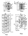
- Les figures 1 et 2 sont des vues schématiques, respectivement en plan et de face, d'un transformateur élémentaire conforme à l'invention.Figures 1 and 2 are schematic views, respectively in plan and front, of an elementary transformer according to the invention.
- Les figures 3 à 6 sont des schémas montrant différentes solutions pour l'alimentation sélective individuelle des différents modules primaires que comporte un transformateur conforme à l'invention.Figures 3 to 6 are diagrams showing different solutions for the selective individual supply of the different primary modules that a transformer according to the invention comprises.
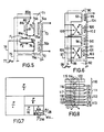
- La figure 7 est un schéma montrant la conception possible d'un transformateur conforme à l'invention.Figure 7 is a diagram showing the possible design of a transformer according to the invention.
- La figure 8 est une vue schématique d'un mode de réalisation particulier de l'invention.Figure 8 is a schematic view of a particular embodiment of the invention.
- La figure 9 est un schéma partiel d'une variante de réalisation.Figure 9 is a partial diagram of an alternative embodiment.
- La figure 10 montre schématiquement une possibilité de bobinage « en huit pour le secondaire commun à deux circuits primaires.FIG. 10 schematically shows a possibility of winding “in eight for the secondary common to two primary circuits.
L'invention a pour objet un transformateur électrique destiné à délivrer une grandeur électrique réglable, notamment à des fins de régulation, comportant plusieurs modules qui ont entre eux une relation de progression binaire et qui sont associés à des moyens de commutation les rendant sélectivement opérant ou inopérant pour la transformation électrique, chaque module comprenant au moins un bobinage de circuit primaire, caractérisé en ce que chacun des primaires de chacun des modules coopère avec un circuit magnétique secondaire qui est commun à tous les modules, en ce que les moyens de commutation sont branchés pour permettre de neutraliser l'effet de l'induction électrique des primaires respectifs sur ledit secondaire commun tout en conservant l'activité magnétique desdits primaires.The subject of the invention is an electrical transformer intended to deliver an adjustable electrical quantity, in particular for regulation purposes, comprising several modules which have a binary progression relationship between them and which are associated with switching means making them selectively operative or inoperative for electrical transformation, each module comprising at least one primary circuit winding, characterized in that each of the primaries of each of the modules cooperates with a secondary magnetic circuit which is common to all the modules, in that the switching means are connected to neutralize the effect of the electrical induction of the respective primaries on said common secondary while retaining the magnetic activity of said primaries.
Selon d'autres caractéristiques de l'invention :
- Les moyens de commutation sont constitués par un connecteur individuel à chaque module et ayant deux positions dans l'une desquelles le bobinage de circuit primaire est alimenté normalement par une tension d'origine nominalement constante et dans l'autre desquelles le circuit magnétique reste activé à partir de la même tension d'origine mais en induisant dans le secondaire une tension nulle par soustraction.
- The switching means consist of an individual connector to each module and having two positions in one of which the primary circuit winding is normally supplied by a nominally constant original voltage and in the other of which the magnetic circuit remains activated at starting from the same original voltage but inducing in the secondary a zero voltage by subtraction.
La tension d'alimentation et chacune de deux bornes du bobinage de circuit primaire de chaque module sont intercalés deux interrupteurs électroniques tels que des thyristors ou des transistors montés tête-bêche et commandés sélectivement pour assurer l'inversion de l'alimentation dudit bobinage de circuit primaire.The supply voltage and each of two terminals of the primary circuit winding of each module are interposed two electronic switches such as thyristors or transistors mounted head to tail and selectively controlled to ensure the reversal of the supply of said circuit winding primary.
Chaque module comprend deux bobinages de circuit primaire alimentés sélectivement, soit pour assurer l'induction dans le bobinage de circuit secondaire, soit pour neutraliser l'effet de cette induction sur ledit secondaire.Each module comprises two primary circuit windings selectively supplied, either to ensure induction in the secondary circuit winding, or to neutralize the effect of this induction on said secondary.
Deux bobinages de circuit primaire sont de sens inverses, un connecteur étant prévu pour établir le contact entre la tension d'origine et l'un ou l'autre de ces deux bobinages de circuit primaire.Two primary circuit windings are in opposite directions, a connector being provided to establish contact between the original voltage and one or the other of these two primary circuit windings.
Deux bobinages sont de même sens et en ce qu'un inverseur est intercalé entre les bornes d'un seul de ces bobinages d'une part et la tension d'origine qui alimente simultanément l'autre bobinage d'autre part.Two windings are in the same direction and in that an inverter is interposed between the terminals of only one of these windings on the one hand and the original voltage which simultaneously supplies the other winding on the other hand.
Le bobinage de circuit primaire du premier module est alimenté par les deux lignes principales d'une source de tension et que le bobinage correspondant .des modules suivants est alimenté à l'une de ses extrémités par l'une des deux lignes principales et à son autre extrémité par une dérivation issue d'un point intermédiaire, notamment médian, du bobinage de circuit primaire du module précédent.The primary circuit winding of the first module is supplied by the two main lines of a voltage source and that the corresponding winding of the following modules is supplied at one of its ends by one of the two main lines and at its other end by a derivation from an intermediate point, notably in the middle, of the primary circuit winding of the previous module.
Les modules ont une tension nominale procurant avec un courant donné une puissance qui est différente pour chaque module, le total de ces puissances individuelles étant sensiblement égal à la puissance maximum admissible pour le circuit secondaire unique.The modules have a nominal voltage providing with a given current a power which is different for each module, the total of these individual powers being substantially equal to the maximum admissible power for the single secondary circuit.
Chaque module comprenant deux circuits magnétiques, un pour chaque primaire de ce module, ces circuits magnétiques ont des longueurs et des largeurs constantes tandis que leurs épaisseurs suivent, d'un module à l'autre, une variation binaire.Each module comprising two magnetic circuits, one for each primary of this module, these magnetic circuits have constant lengths and widths while their thicknesses follow, from one module to another, a binary variation.
En se reportant aux figures 1 et 2, on voit qu'un transformateur conforme à l'invention peut comprendre, comme ici, deux modules qui comprennent chacun un seul bobinage primaire respectivement 1 et 2 associés chacun à un circuit magnétique respectivement 3 et 4, ces deux circuits primaires étant associés à un seul bobinage de circuit secondaire 5 commun aux deux modules 1 et 2.Referring to FIGS. 1 and 2, it can be seen that a transformer according to the invention can comprise, as here, two modules which each comprise a single primary winding respectively 1 and 2 each associated with a magnetic circuit respectively 3 and 4, these two primary circuits being associated with a single secondary circuit winding 5 common to the two modules 1 and 2.
Chaque bobinage primaire 1 et 2 est relié indépendamment à une source de tension 6 nominalement constante, par exemple 220 volts.Each primary winding 1 and 2 is independently connected to a nominally constant voltage source 6, for example 220 volts.
Pour chaque bobinage, se trouve un commutateur respectivement 7 et 8 pouvant occuper deux positions dans l'une desquelles il établit le circuit normal (connecteur 8 sur les figures 1 et 2) tandis que dans l'autre (connecteur 7 figure 1), il met le bobinage correspondant en court-circuit.For each winding, there is a switch respectively 7 and 8 which can occupy two positions in one of which it establishes the normal circuit (connector 8 in Figures 1 and 2) while in the other (
De la sorte, selon que le commutateur de chaque bobinage de circuit primaire est dans l'une ou l'autre de ses deux positions, le circuit secondaire unique 5 a une tension qui correspond soit à celle qui résulte du bobinage 1 seulement, soit à celle qui résulte du bobinage 2 seulement soit à celle qui résulte de l'action des deux bobinages 1 et 2 à la fois.In this way, depending on whether the switch of each primary circuit winding is in one or other of its two positions, the single secondary circuit 5 has a voltage which corresponds either to that which results from the winding 1 only, or to that which results from the winding 2 only is that which results from the action of the two windings 1 and 2 at the same time.
Une installation complète comprenant un transformateur conforme à l'invention, est équipé d'un dispositif de commande, éventuellement programmé, et agissant sur tous les connecteurs pour agir sélectivement sur l'alimentation individuelle de chaque module primaire.A complete installation comprising a transformer according to the invention is equipped with a control device, possibly programmed, and acting on all the connectors to act selectively on the individual power supply of each primary module.
Il en résulte qu'en calibrant convenablement les modules primaires, on peut atteindre un très grand degré de précision et de finesse de réglage.As a result, by properly calibrating the primary modules, a very high degree of precision and fine tuning can be achieved.
Naturellement, une version simple consiste à prévoir une pluralité de modules tous égaux entre eux.Naturally, a simple version consists in providing a plurality of modules all equal to each other.
Mais, selon une version plus élaborée, il est intéressant de prévoir que les modules ont une tension nominale qui est établie pour procurer, avec un courant donné, une puissance qui est différente pour chaque module.However, according to a more elaborate version, it is advantageous to provide that the modules have a nominal voltage which is established to provide, with a given current, a power which is different for each module.
Le total de ces puissances individuelles est sensiblement égal à la puissance maximum admissible pour le circuit secondaire unique.The total of these individual powers is substantially equal to the maximum admissible power for the single secondary circuit.
Selon une variante de l'invention qui s'avère être particulièrement intéressante, les modules sont des fractions dégressives régulières de la puissance totale et s'établissent selon un code binaire.According to a variant of the invention which proves to be particularly advantageous, the modules are regular decreasing fractions of the total power and are established according to a binary code.
En d'autres termes, le dénominateur de chaque fraction est une puissance entière de 2 de sorte que le module le plus puissant est égal à la moitié de la puissance totale P, soit P/2, les autres moitiés ayant une puissance égale respectivement à P/4, P/8, P/16, P/32, P/64, etc...In other words, the denominator of each fraction is an integer power of 2 so that the most powerful module is equal to half of the total power P, or P / 2, the other halves having a power equal to respectively P / 4, P / 8, P / 16, P / 32, P / 64, etc ...
On voit, ainsi, que le pas de réglage, ou saut minimum, est égal à la plus petite fraction de P prévue dans le transformateur.It can thus be seen that the adjustment step, or minimum jump, is equal to the smallest fraction of P provided in the transformer.
Il est par conséquent possible dans la pratique, sans aucune difficulté, de réaliser un transformateur composé d'une pluralité de modules de dimensions décroissantes qui, au nombre de huit procurent une finesse de réglage égale à 1/255 pour le dernier module ce qui est une excellente performance (1/255 = P/N-1).It is therefore possible in practice, without any difficulty, to make a transformer composed of a plurality of modules of decreasing dimensions which, eight in number provide a fineness of adjustment equal to 1/255 for the last module which is excellent performance (1/255 = P / N-1).
Lorsque la puissance demandée est égale à P/2, on n'active que le module N° 1. Si l'on désire l'augmenter de P/255, on active en plus le module N° 8. Pour l'augmenter encore de P/255 on active le module ? 7 en neutralisant, simultanément le module N° 8 etc...When the requested power is equal to P / 2, only module N ° 1 is activated. If one wishes to increase it by P / 255, module N ° 8 is also activated. To increase it further from P / 255 we activate the module? 7 by simultaneously neutralizing module No. 8 etc ...
Chaque module'étant commandé sélectivement, toutes les combinaisons sont possibles avec une finesse de réglage égale à P/N-1, N-1 étant-la fraction de la puissance du dernier module d'un ensemble donné.Each module being selectively controlled, all combinations are possible with a fine adjustment equal to P / N-1, N-1 being the fraction of the power of the last module of a given set.
Il faut souligner, car cela est une caractéristique intéressante de l'invention, que chaque module primaire est peu volumineux et que le passage d'un réglage au 1/127 à un réglage au 1/255 ne nécessite que l'adjonction d'un transformateur supplémentaire de très petites dimensions.It should be emphasized, because this is an interesting characteristic of the invention, that each primary module is not very bulky and that the passage from a setting at 1/127 to a setting at 1/255 requires only the addition of a extra transformer of very small dimensions.
En se reportant maintenant à la figure 3, on voit un schéma électrique d'un transformateur conforme à l'invention comprenant six modules identiques 10 à 15 et, bien entendu, toujours un seul bobinage de circuit secondaire 16.Referring now to FIG. 3, we see an electrical diagram of a transformer according to the invention comprising six
Chaque module comprend un bobinage 17 à 22 associé à un circuit magnétique individuel 23 à 28.Each module comprises a
La source de tension alternative 30 est reliée à deux lignes principales 31 et 32 sur lesquelles sont branchées les alimentations individuelles de chaque module primaire respectivement 33 à 38 et 39 à 44.The
Le type de connexion choisi est celui qui a déjà été décrit en regard des figures 1 et 2 c'est-à-dire que chaque module 10 à 15 est associé à un connecteur respectivement 45 à 50 mobile entre deux positions correspondant à l'alimentation normale ou à la mise en court-circuit de chaque bobinage 17 à 22.The type of connection chosen is that which has already been described with reference to FIGS. 1 and 2, that is to say that each
Pour simplifier le dessin, on a représenté tous les modules 10 à 15 comme s'ils avaient tous les mêmes dimensions.To simplify the drawing, all the
Cependant, dans la réalité, si on adopte le mode de réalisation préféré selon lequel les modules procurent des puissances différentes, il est clair qu'ils ont des dimensions d'autant plus faibles que la puissance développée est elle-même faible.However, in reality, if we adopt the preferred embodiment according to which the modules provide different powers, it is clear that they have dimensions the smaller the power developed is itself low.
Si l'on retient la variation binaire de cette puissance par rapport à la puissance totale P admissible par l'unique bobinage de circuit secondaire 16, on a pour le module 10 une puissance égale à P/2, pour le module 11 une puissance égale à P/4, etc...If we take the binary variation of this power with respect to the total power P admissible by the single secondary circuit winding 16, we have for module 10 a power equal to P / 2, for module 11 an equal power to P / 4, etc ...
En supposant que l'installation est alimentée en 220 Volts avec un courant efficace de 48 Ampères, on obtient les résultats groupés dans le tableau ci-après :

Il ressort de la description ci-dessus, que la tension du secondaire est fonction du nombre de modules sous tension et qu'elle peut, de ce fait, varier de 0 à 100 pour 100 en modifiant le rapport du nombre de spires des bobinages primaires au nombre de spires du bobinage secondaire en prenant la précaution de shunter les bobinages des modules non activés pour leur donner une impédance nulle, ce qui est bien le cas puisque le secondaire devient alors conducteur.It emerges from the description above, that the voltage of the secondary is a function of the number of modules under voltage and that it can, therefore, vary from 0 to 100 per 100 by modifying the ratio of the number of turns of the primary windings the number of turns of the secondary winding, taking the precaution of shunting the windings of the non-activated modules to give them zero impedance, this which is indeed the case since the secondary then becomes conductive.
Le transformateur unique conforme à l'invention fonctionne, en quelque sorte, comme une série de transformateurs dont les secondaires seraient tous en série.The single transformer according to the invention functions, in a way, like a series of transformers, the secondaries of which are all in series.
Cette solution entraîne une économie massique très sensible puisque la puissance d'un tel transformateur-variateur est la même que celle qu'aurait un transformateur classique sans réglage.This solution results in a very significant mass saving since the power of such a transformer-variator is the same as that which a conventional transformer would have without adjustment.
En se reportant maintenant à la figure 4, on va décrire un transformateur du même type que celui qui a été décrit précédemment, c'est-à-dire dont chaque module ne comprend qu'un seul bobinage primaire, mais avec l'utilisation de thyristors tête-bêche pour agir sélectivement sur l'induction produite par le bobinage primaire.Referring now to FIG. 4, we will describe a transformer of the same type as that which has been described previously, that is to say of which each module comprises only one primary winding, but with the use of head-to-tail thyristors to act selectively on the induction produced by the primary winding.
Sur cette figure, on n'a représenté que deux modules respectivement 51 et 52 mais l'ébauche du module 53 montre que l'on peut, comme cela résulte des explications précédentes, prévoir un nombre de modules quelconque au-dessus de deux.In this figure, only two
Chaque module comprend un bobinage de circuit primaire respectivement 54 et 55 et un circuit magnétique individuel 56 et 57.Each module includes a primary circuit winding 54 and 55 respectively and an individual
Chaque module est alimenté à partir d'une source de tension 58 raccordée à deux lignes principales 59 et 60 à chacune desquelles sont raccordées les bornes des deux bobinages 54 et 55. Chacune de ces bornes 54a et 54b d'une part, 55a et 55b d'autre part aboutit à une dérivation à deux branches sur chacune desquelles se trouve un thyristor, lesquels sont montés tête-bêche pour les mêmes dérivations : 61 et 62-63 et 64-65 et 66-67 et 68.Each module is supplied from a
Ces thyristors sont commandés par tous moyens électroniques connus de telle manière que dans le même bobinage primaire donné soit envoyé un courant, soit dans un sens soit dans l'autre.These thyristors are controlled by any known electronic means such that in the same given primary winding is sent a current, either in one direction or in the other.
Il en résulte que dans un cas le bobinage secondaire unique 70 est le siège d'une tension qui, le cas échéant, s'ajoute aux autres tensions nées des autres modules, tandis que dans l'autre cas aucune tension n'est induite dans le bobinage secondaire.It follows that in one case the single secondary winding 70 is the seat of a voltage which, if necessary, is added to the other voltages arising from the other modules, while in the other case no voltage is induced in the secondary winding.
On voit ainsi que selon le sens dans lequel le bobinage est parcouru il y a neutralisation de l'effet d'induction.It can thus be seen that, depending on the direction in which the winding is traversed, the induction effect is neutralized.
Mais, ici encore, la magnétisation des circuits magnétiques est permanente, quel que soit le sens effectif du courant. En d'autres termes, les circuits magnétiques sont toujours alimentés, mais la tension dans le bobinage secondaire est soit effectivement induite soit nulle.But, here again, the magnetization of the magnetic circuits is permanent, whatever the effective direction of the current. In other words, the magnetic circuits are always supplied, but the voltage in the secondary winding is either effectively induced or zero.
La solution électronique qui vient d'être décrite présente de nombreux avantages parmi lesquels on peut citer le fait que l'enclenchement et la rupture se font au zéro de la sinusoïde de sorte que quelle que soit la combinaison utilisée pour les modules, il y a conservation du régime sinusoïdal pur.The electronic solution which has just been described has many advantages among which we can cite the fact that the engagement and the break are made at the zero of the sinusoid so that whatever the combination used for the modules, there is conservation of the pure sinusoidal regime.
En outre, l'emploi de thyristors ou de transistors pour effectuer la commutation d'une manière sélective des modules, permet d'obtenir des vitesses de commutation extrêmement grandes, nécessaires pour réguler des grandeurs électriques à très hautes performances.In addition, the use of thyristors or transistors to effect the selective switching of the modules makes it possible to obtain extremely high switching speeds, necessary for regulating electrical quantities with very high performance.
En se reportant maintenant aux figures 5 et 6, on voit un autre mode de réalisation de l'invention selon lequel chaque module comprend deux bobinages de circuit primaire.Referring now to Figures 5 and 6, there is shown another embodiment of the invention according to which each module comprises two primary circuit windings.
Sur la figure 5 on a représenté un module complet 71 et l'amorce d'un second 72 avec, comme toujours, un seul et unique bobinage de circuit secondaire 73.FIG. 5 shows a complete module 71 and the start of a second 72 with, as always, a single secondary circuit winding 73.
Chaque module comprend un circuit magnétique 74 et deux bobinages de même pas respectivement 75 et 76.Each module includes a magnetic circuit 74 and two coils of the same pitch, respectively 75 and 76.
Une source de tension 77 est reliée à deux lignes 78 et 79, cette dernière aboutissant directement à l'une des bornes 76a du bobinage 76 et à la borne 80a d'un connecteur 80.A voltage source 77 is connected to two
La ligne 78 aboutit à une dérivation à deux branches dont l'une aboutit à la borne 76b du bobinage 76 et l'autre est reliée d'une part à la borne 75a du bobinage 75 et d'autre part, à la borne 81a d'un bobinage 81 dont le pas est inverse de celui du bobinage 75 et dont la seconde borne 81 b peut être reliée à la ligne 79, comme la borne 75b, selon la position du connecteur 80.
Avec ce montage, on voit que le courant qui se divise selon les flèches F1 et F2 parcourt toujours le bobinage 76 et, selon la position du connecteur 80, parcourt soit le bobinage 75 soit le bobinage 81.With this arrangement, it can be seen that the current which divides according to the arrows F1 and F2 always flows through the
Dans le premier cas une tension est induite dans le bobinage secondaire 73 et cette tension vient s'ajouter à la tension induite du bobinage 76 tandis que dans l'autre cas le bobinage 81 ayant un enroulement de pas inverse du bobinage 75, la tension induite dans le bobinage secondaire 73 vient non plus s'ajouter mais se soustraire à la tension induite à partir du bobinage primaire 76 de sorte que, finalement, le bobinage secondaire 73 est parcouru soit par la tension nominale du module 71 soit par une tension nulle pour le même module 71.In the first case a voltage is induced in the secondary winding 73 and this tension is added to the induced voltage of the winding 76 while in the other case the winding 81 having a reverse pitch winding of the winding 75, the induced voltage in the secondary winding 73 is no longer added to but subtracted from the voltage induced from the primary winding 76 so that, ultimately, the secondary winding 73 is traversed either by the nominal voltage of the module 71 or by a zero voltage for the same module 71.
Dans cette hypothèse, le bobinage secondaire 73 est parcouru, le cas échéant, par les seules tensions induites par les autres modules.In this case, the secondary winding 73 is traversed, if necessary, by the only voltages induced by the other modules.
En se reportant maintenant à la figure 6, on voit un montage qui lui aussi comprend deux bobinages primaires pour chaque module mais, ici, la neutralisation de chaque module s'obtient par des moyens différents.Referring now to FIG. 6, we can see an assembly which also includes two primary windings for each module but, here, the neutralization of each module is obtained by different means.
On a représenté deux modules complets 90 et 91 et l'ébauche d'un troisième 92.Two
Chacun de ces deux modules comprend un bobinage primaire 93 et 94 associé à un circuit magnétique 95 et 96 et dont les bornes sont reliées en permanence à deux lignes 97 et 98 alimentées par une source 99.Each of these two modules comprises a primary winding 93 and 94 associated with a
En outre, chacun de ces modules comprend un deuxième bobinage respectivement 100 et 101 associé à un circuit magnétique 102 et 103, l'ensemble des modules correspondant, comme toujours, à un unique bobinage secondaire 104.In addition, each of these modules comprises a second winding 100 and 101 respectively. associated with a
Entre les lignes 97 et 98 d'une part et les bornes des bobinages 100 et 101 d'autre part, sont intercalés des inverseurs respectivement 105 et 106.Between the
On comprend qu'avec ce montage, selon la position que l'on donne à chaque inverseur situé dans chaque module, le bobinage correspondant 100, 101, etc... est parcouru de la même manière que le bobinage correspondant 93, 94, etc... ou se trouve en opposition de sorte que, comme dans le cas de la figure 5, le bobinage secondaire 104 est parcouru par une tension induite qui s'ajoute ou qui se retranche à celle, permanente, des bobinages 93, 94, etc...We understand that with this arrangement, depending on the position that is given to each inverter located in each module, the corresponding winding 100, 101, etc ... is traversed in the same way as the corresponding winding 93, 94, etc. ... or is in opposition so that, as in the case of FIG. 5, the secondary winding 104 is traversed by an induced voltage which is added or subtracted from that, permanent, of the
La tension aux bornes du bobinage secondaire 104 est donc bien le résultat d'une addition des tensions de chaque module activé.The voltage across the secondary winding 104 is therefore the result of an addition of the voltages of each activated module.
En se reportant maintenant à la figure 7, on voit que l'on a représenté graphiquement la manière de diviser la puissance totale P admissible par le bobinage secondaire en des modules ayant chacun, pour un courant donné, une puissance qui est une fraction régulièrement dégressive de la puissance P.Referring now to FIG. 7, we see that we have graphically represented the way of dividing the total power P admissible by the secondary winding into modules each having, for a given current, a power which is a regularly declining fraction of the power P.
Ce graphique tend à montrer visuellement que l'on peut sans difficulté atteindre une extrême finesse de réglage puisque l'on pourrait, quelle que soit la puissance P, prévoir un dernier module de puissance égale à P/128 ou même P/256 ou P/512 etc...This graph tends to show visually that one can easily reach an extreme fineness of adjustment since one could, whatever the power P, provide a last power module equal to P / 128 or even P / 256 or P / 512 etc ...
Ce graphique montre également que l'obtention de cette finesse se fait moyennant un module extrêmement compact et donc bon marché alors que généralement l'augmentation d'une performance donnée est proportionnellement beaucoup plus compliquée et coûteuse que la performance elle-même.This graph also shows that obtaining this finesse is done by means of an extremely compact and therefore inexpensive module whereas generally the increase in a given performance is proportionally much more complicated and costly than the performance itself.
Sur la figure 8, on a schématisé un transformateur conforme à l'invention comprenant quatre modules du type selon lequel chacun de ceux-ci comprend deux bobinages primaires et deux circuits magnétiques.In Figure 8, there is shown schematically a transformer according to the invention comprising four modules of the type according to which each of these comprises two primary windings and two magnetic circuits.
On voit que pour chaque module 110,111,112 et 113 les deux bobinages respectivement 114 et 115, 116 et 117, 118 et 119,120 et 121 sont égaux de même que les circuits magnétiques correspondants 1.22 et 123, 124 et 125, 126 et 127, 128 et 129.We see that for each module 110,111,112 and 113 the two windings respectively 114 and 115, 116 and 117, 118 and 119,120 and 121 are equal as well as the corresponding magnetic circuits 1.22 and 123, 124 and 125, 126 and 127, 128 and 129 .
Il est en effet fondamental que les deux circuits primaires et les deux circuits magnétiques de chaque module soient rigoureusement égaux pour que l'un puisse neutraliser l'autre.It is indeed fundamental that the two primary circuits and the two magnetic circuits of each module are strictly equal so that one can neutralize the other.
On comprend, bien entendu, que la tension résultante est soit nulle, soit égale à l'addition des deux circuits primaires de chaque module.It is understood, of course, that the resulting voltage is either zero or equal to the addition of the two primary circuits of each module.
Chaque module a une fonction binaire, 0 et 1, obtenue par l'inversion du champ d'un primaire par rapport à l'autre.Each module has a binary function, 0 and 1, obtained by inverting the field of one primary with respect to the other.
La figure 9 représente un schéma d'une variante selon laquelle une dérivation est connectée au milieu de l'un des deux enroulements de chaque module et constitue l'alimentation de l'enroulement correspondant du module suivant.FIG. 9 represents a diagram of a variant according to which a branch is connected in the middle of one of the two windings of each module and constitutes the supply of the corresponding winding of the following module.
Ainsi, par exemple, le module 140 est alimenté en 220 Volts à partir de la source 141 par deux lignes principales 142 et 143. Cette tension est appliquée à l'enroulement 144 associé à un homologue 145.Thus, for example, the
Du milieu de l'enroulement 144, part une dérivation 146 qui aboutit à l'extrémité de l'enroulement correspondant 147 associé à un homologue 148 du module suivant 149. L'autre extrémité de l'enroulement 147 est reliée directement à la ligne 142 de sorte que la tension d'alimentation de l'enroulement 147 est de 110 Volts seulement.From the middle of the winding 144, a
De la même manière, l'enroulement 150 associé à l'enroulement 151 du module 152 est alimenté en 55 Volts et ainsi de suite, le secondaire 153 étant toujours unique et commun à tous les modules.In the same way, the winding 150 associated with the winding 151 of the
Le premier module 140 a une puissance de P/2 avec un courant de i/4 pour un courant nominal de i. Le module 149 a P/4 et i/8. Le module 152 a P/8 et i/16 etc...The
Avec cette variante, le nombre de spires des enroulements du primaire est constant pour tous les modules, quelle que soit leur puissance. On parvient de la sorte à une standardisation qui conduit à une économie de main d'oeuvre.With this variant, the number of turns of the primary windings is constant for all modules, regardless of their power. In this way, a standardization is achieved which leads to a saving in labor.
D'autre part, on réalise des économies de matière première (cuivre) puisque le courant, dans chaque module, a une valeur décroissante pour laquelle le diamètre du fil de bobinage peut être exactement adapté. Pour un ensemble de module, on parvient à une excellente adéquation entre le courant et la quantité de cuivre nécessaire et suffisante.On the other hand, savings are made in raw material (copper) since the current in each module has a decreasing value for which the diameter of the winding wire can be exactly adapted. For a set of modules, an excellent match is obtained between the current and the quantity of copper necessary and sufficient.
Les détails pratiques de la construction d'un transformateur conforme à l'invention sont à la portée de l'homme de métier mais on peut citer, toutefois, les dispositions ci-après :
- plutôt que d'avoir des dimensions rationnelles, certes, mais peu pratiques comme celles qui sont schématisées sur la figure 7, il est préférable de prévoir pour les circuits magnétiques des dimensions constantes pour ce qui est de la longueur et de la largeur tandis que l'on fait varier seulement l'épaisseur selon la puissance désirée pour chaque module.
- rather than having rational dimensions, certainly, but impractical like those shown in Figure 7, it is better to provide for magnetic circuits constant dimensions in terms of length and width while l 'we only vary the thickness according to the desired power for each module.
Ce mode de construction est schématisé par la figure 8.This construction method is shown diagrammatically in FIG. 8.
Un exemple chiffré se trouve dans le tableau de la page 8 où la dernière colonne indique l'épaisseur du circuit magnétique en millimètres comme seule dimension variable d'un module à l'autre, la longueur et la largeur étant établies une fois pour toutes.A numerical example is found in the table on page 8 where the last column indicates the thickness of the magnetic circuit in millimeters as the only variable dimension from one module to another, the length and the width being established once and for all.
Plutôt que de construire un important transformateur composé exclusivement de modules conformes à l'invention, il est possible d'associer un transformateur banal à un transformateur conforme à l'invention et comportant plusieurs modules de petite puissance, ce transformateur agissant comme régulateur du premier.Rather than building a large transformer composed exclusively of modules according to the invention, it is possible to associate a common transformer with a transformer according to the invention and comprising several low power modules, this transformer acting as regulator of the first.
Une application de ce principe se trouve dans les transformateurs de ligne auxquels on peut adjoindre quelques modules qui régulent automatiquement les variations de tension.An application of this principle is found in line transformers to which we can add a few modules that automatically regulate voltage variations.
La possibilité de combiner un gros transformateur à tension constante et un transformateur conforme à l'invention à tension réglagle, conduit à quatre solutions possibles qui sont respectivement :
- la réalisation d'un transformateur complet conforme à l'invention dans une seule structure ;
- la réalisation dans une première structure d'un transformateur à tension constante et d'une partie modulaire conforme à l'invention puis, dans une deuxième structure, un ensemble de modules ne servant qu'aux réglages fins de la puissance minimum :
- la réalisation dans deux structures différentes d'un transformateur à tension constante et d'un transformateur modulaire conforme à l'invention, ces deux structures étant électriquement connectées ;
- la réalisation d'un ensemble de régulation comprenant d'une part un transformateur à tension constante aux bornes du secondaire et d'autre part, un transformateur à tension réglable au primaire dans la plage de -15 à + 15 %.
- the production of a complete transformer according to the invention in a single structure;
- the production in a first structure of a constant voltage transformer and a modular part according to the invention then, in a second structure, a set of modules used only for fine adjustments of the minimum power:
- the production in two different structures of a constant voltage transformer and a modular transformer according to the invention, these two structures being electrically connected;
- the production of a regulation assembly comprising on the one hand a transformer with constant voltage across the secondary and on the other hand, a transformer with adjustable voltage at the primary in the range from -15 to + 15%.
Comme indiqué plus haut, la commande des différents modules peut être obtenue soit par des moyens électro-mécaniques, soit par des moyens électroniques.As indicated above, the control of the various modules can be obtained either by electro-mechanical means, or by electronic means.
Lorsque le circuit primaire des modules comporte deux bobinages et deux circuits magnétiques. l'enroulement peut être obtenu soit indépendamment pour chacun d'eux soit en continu pour les deux bobinages en donnant à chaque spire un parcours « en 8 •, comme cela est schématisé sur la figure 10.When the primary circuit of the modules has two windings and two magnetic circuits. the winding can be obtained either independently for each of them or continuously for the two windings by giving each turn a “8” path, as shown in FIG. 10.
Le régime sinusoïdal restant pur à tous les instants, un transformateur selon l'invention permet d'alimenter un redresseur en conservant son ondulation résiduelle naturelle.The sinusoidal regime remaining pure at all times, a transformer according to the invention makes it possible to supply a rectifier while retaining its natural residual ripple.
Il faut noter que la disposition de deux circuits magnétiques avec deux circuits primaires pour chaque module donne des résultats tout à fait différents du montage connu sous le nom de « shunt magnétique car celui-ci n'a pas d'enroulement primaire. Il en résulte des fuites créant un déphasage courant-tension important d'où un cosinus <p médiocre.It should be noted that the arrangement of two magnetic circuits with two primary circuits for each module gives results quite different from the assembly known as the “magnetic shunt because it has no primary winding. This results in leaks creating a large current-voltage phase shift, hence a mediocre cosine <p.
Selon l'invention, au contraire, on obtient un cosinus voisin de 1 avec les réalisations du type représenté notamment sur les figures 1 et 8.According to the invention, on the contrary, a cosine close to 1 is obtained with the embodiments of the type shown in particular in FIGS. 1 and 8.
On peut prévoir un transformateur modulaire conforme à l'invention utilisant des solutions mixtes électro-mécaniques et électroniques notamment en prévoyant des thyristors pour le dernier module seulement, ces thyristors ne jouant que sur une fraction infime de la sinusoïde et ne provoquant une variation de puissance que dans des proportions absolument insignifiantes avec un taux de distorsion très réduit.A modular transformer can be provided in accordance with the invention using mixed electro-mechanical and electronic solutions, in particular by providing thyristors for the last module only, these thyristors acting only on a tiny fraction of the sinusoid and causing a variation in power only in absolutely insignificant proportions with a very reduced distortion rate.
Il ressort que la description ci-dessus, que l'invention permet de réaliser un transformateur à tension réglable qui comprend des avantages extrêmement marqués par rapport aux dispositifs connus :
- A tout instant la charge appliquée au secondaire reste sous tension et, celà, même pendant le temps des interruptions dues aux commutations.
- At all times the load applied to the secondary remains energized and this, even during the time of interruptions due to switching.
La coupure et la fermeture des circuits de mise en action des modules se fait au 0 de la sinusoïde puisque la modification du nombre de modules utilisés a pour conséquence une action sur l'amplitude de la sinusoïde.The module actuation circuits are cut and closed at 0 on the sinusoid since the modification of the number of modules used has an effect on the amplitude of the sinusoid.
La surface de fuite est réduite au minimum et est identique à celle d'un transformateur normal de haute performance et notamment avec des réalisations représentées sur les figures 1 et 8.The leakage surface is reduced to a minimum and is identical to that of a normal high performance transformer and in particular with the embodiments shown in Figures 1 and 8.
La commutation se fait sans rupture de charge.Switching takes place without a load break.
Le réglage se fait selon une progression pas-à-pas extrêmement fine.The adjustment is made in an extremely fine step-by-step progression.
On peut utiliser des dispositifs de stabilisation de tous types connus.Stabilization devices of all known types can be used.
La puissance est illimitée.The power is unlimited.
Un transformateur conforme à l'invention a un rendement égal à celui d'un transformateur normal.A transformer according to the invention has an efficiency equal to that of a normal transformer.
Le réglage se fait sans aucune interruption de l'alimentation électrique.The adjustment is made without any interruption of the power supply.
La variation de tension est réalisée à partir d'un système d'asservissement pas-à-pas qui évite une mise à zéro de la tension du secondaire, lorsqu'il faut la moduler.The voltage variation is carried out using a step-by-step servo system which avoids setting the secondary voltage to zero when it has to be modulated.
Claims (9)
Priority Applications (1)
| Application Number | Priority Date | Filing Date | Title |
|---|---|---|---|
| AT83400904T ATE31589T1 (en) | 1982-05-25 | 1983-05-05 | ELECTRICAL TRANSFORMER WITH MODULAR, SELECTIVELY POWERED PRIMARY CIRCUITS. |
Applications Claiming Priority (2)
| Application Number | Priority Date | Filing Date | Title |
|---|---|---|---|
| FR8208998A FR2527832A1 (en) | 1982-05-25 | 1982-05-25 | ELECTRICAL TRANSFORMER WITH MODULAR PRIMARY CIRCUITS POWERED SELECTIVELY |
| FR8208998 | 1982-05-25 |
Publications (2)
| Publication Number | Publication Date |
|---|---|
| EP0095398A1 EP0095398A1 (en) | 1983-11-30 |
| EP0095398B1 true EP0095398B1 (en) | 1987-12-23 |
Family
ID=9274274
Family Applications (1)
| Application Number | Title | Priority Date | Filing Date |
|---|---|---|---|
| EP83400904A Expired EP0095398B1 (en) | 1982-05-25 | 1983-05-05 | Electric transformer with modular, selectively fed primary circuits |
Country Status (6)
| Country | Link |
|---|---|
| US (1) | US4678986A (en) |
| EP (1) | EP0095398B1 (en) |
| JP (1) | JPS58213409A (en) |
| AT (1) | ATE31589T1 (en) |
| DE (1) | DE3375052D1 (en) |
| FR (1) | FR2527832A1 (en) |
Families Citing this family (21)
| Publication number | Priority date | Publication date | Assignee | Title |
|---|---|---|---|---|
| US4837497A (en) * | 1987-12-29 | 1989-06-06 | Gregory Leibovich | Variable transformer, reactor and method of their control |
| US5177460A (en) * | 1990-01-04 | 1993-01-05 | Dhyanchand P John | Summing transformer for star-delta inverter having a single secondary winding for each group of primary windings |
| JPH05128324A (en) * | 1991-11-07 | 1993-05-25 | Mitsubishi Electric Corp | Non-contact card, terminal machine for non-contact card, and non-contact transmission system |
| US5355296A (en) * | 1992-12-10 | 1994-10-11 | Sundstrand Corporation | Switching converter and summing transformer for use therein |
| GB2284939A (en) * | 1993-08-15 | 1995-06-21 | Aziz Fawzy Mekaiel Fanouse | Voltage regulating transformer |
| JP3416809B2 (en) * | 1994-05-27 | 2003-06-16 | 成勲 井本 | Electric regulator |
| US6340851B1 (en) | 1998-03-23 | 2002-01-22 | Electric Boat Corporation | Modular transformer arrangement for use with multi-level power converter |
| US6212430B1 (en) | 1999-05-03 | 2001-04-03 | Abiomed, Inc. | Electromagnetic field source with detection of position of secondary coil in relation to multiple primary coils |
| US6664881B1 (en) | 1999-11-30 | 2003-12-16 | Ameritherm, Inc. | Efficient, low leakage inductance, multi-tap, RF transformer and method of making same |
| US6806803B2 (en) * | 2002-12-06 | 2004-10-19 | Square D Company | Transformer winding |
| US6867987B2 (en) * | 2003-06-13 | 2005-03-15 | Ballard Power Systems Corporation | Multilevel inverter control schemes |
| KR101432047B1 (en) * | 2007-09-20 | 2014-08-20 | 삼성전자주식회사 | Digital to analog converter |
| CN101692392B (en) * | 2009-09-08 | 2011-05-11 | 武汉泰普变压器开关有限公司 | Non-excitation cage-type positive and negative voltage regulation tap switch for transformer |
| WO2012087816A2 (en) | 2010-12-20 | 2012-06-28 | Abiomed, Inc. | Method and apparatus for accurately tracking available charge in a transcutaneous energy transfer system |
| US8766788B2 (en) | 2010-12-20 | 2014-07-01 | Abiomed, Inc. | Transcutaneous energy transfer system with vibration inducing warning circuitry |
| US9002469B2 (en) | 2010-12-20 | 2015-04-07 | Abiomed, Inc. | Transcutaneous energy transfer system with multiple secondary coils |
| EP3485819B1 (en) | 2011-04-14 | 2022-09-07 | Abiomed, Inc. | Transcutaneous energy transfer coil with integrated radio frequency antenna |
| US9002468B2 (en) | 2011-12-16 | 2015-04-07 | Abiomed, Inc. | Automatic power regulation for transcutaneous energy transfer charging system |
| US9564266B2 (en) | 2014-10-31 | 2017-02-07 | Raytheon Company | Power converter magnetics assembly |
| US9730366B2 (en) | 2015-02-10 | 2017-08-08 | Raytheon Company | Electromagnetic interference suppressing shield |
| US10270356B2 (en) | 2016-08-09 | 2019-04-23 | Raytheon Company | High voltage high frequency power converter |
Family Cites Families (9)
| Publication number | Priority date | Publication date | Assignee | Title |
|---|---|---|---|---|
| NL278413A (en) * | 1961-05-15 | |||
| FR1422650A (en) * | 1965-01-26 | 1965-12-24 | Device for connecting electrical elements, such as resistance, capacitor, inductor or the like, as well as assemblies provided with a connection device, in accordance with the invention | |
| JPS50497Y1 (en) * | 1970-08-13 | 1975-01-09 | ||
| FR2155839B1 (en) * | 1971-10-08 | 1975-04-18 | Alsthom Cgee | |
| FR2179507B1 (en) * | 1972-04-10 | 1975-03-21 | Drusch Gaston | |
| JPS5232625B2 (en) * | 1973-03-29 | 1977-08-23 | ||
| US4011499A (en) * | 1976-02-11 | 1977-03-08 | The Bendix Corporation | Low loss a.c. voltage regulator |
| FR2406908A1 (en) * | 1977-10-19 | 1979-05-18 | Sirven Pierre | Binary controlled AC supply regulator - uses 7 transformers to provide voltage components as required according to input 7-bit binary number |
| GB2063572A (en) * | 1979-11-06 | 1981-06-03 | Westinghouse Electric Corp | Tap changer for electrical inductive apparatus |
-
1982
- 1982-05-25 FR FR8208998A patent/FR2527832A1/en active Granted
-
1983
- 1983-05-05 AT AT83400904T patent/ATE31589T1/en not_active IP Right Cessation
- 1983-05-05 EP EP83400904A patent/EP0095398B1/en not_active Expired
- 1983-05-05 DE DE8383400904T patent/DE3375052D1/en not_active Expired
- 1983-05-24 JP JP58090116A patent/JPS58213409A/en active Pending
-
1986
- 1986-04-24 US US06/856,449 patent/US4678986A/en not_active Expired - Fee Related
Also Published As
| Publication number | Publication date |
|---|---|
| FR2527832A1 (en) | 1983-12-02 |
| US4678986A (en) | 1987-07-07 |
| JPS58213409A (en) | 1983-12-12 |
| FR2527832B1 (en) | 1984-11-23 |
| EP0095398A1 (en) | 1983-11-30 |
| DE3375052D1 (en) | 1988-02-04 |
| ATE31589T1 (en) | 1988-01-15 |
Similar Documents
| Publication | Publication Date | Title |
|---|---|---|
| EP0095398B1 (en) | Electric transformer with modular, selectively fed primary circuits | |
| FR2471702A1 (en) | BIPOLAR CIRCUIT AND AUTOCONTROL FIELD EFFECT OF SWITCHING | |
| FR2584858A1 (en) | CIRCUIT SWITCH WITHOUT ARC FORMATION | |
| WO1981003722A1 (en) | Transistor or thyristor inverter with energy recovery | |
| FR2575324A1 (en) | SYNCHRONOUSLY OPERATING ELECTRIC CURRENT SWITCH DEVICE FOR SWITCHING MULTIPLE CIRCUITS AND / OR REDUCING CONTACT RESISTANCE | |
| FR2736767A1 (en) | DEVICE FOR COMPENSATION OF A GROUNDING CURRENT OF A POLYPHASE ELECTRICAL NETWORK | |
| CH648708A5 (en) | ADJUSTABLE VOLTAGE DIRECT CURRENT SUPPLY DEVICE INCLUDING A VARIABLE TRANSFORMER. | |
| CH651990A5 (en) | MODULATION INSTALLATION FOR THE POWER SUPPLY OF POWER ORGANS. | |
| EP1450474B1 (en) | Converter and direct energy transfer | |
| FR2547104A1 (en) | HIGH PRECISION VOLTAGE TRANSFORMER | |
| EP0147306A2 (en) | Linear power amplifier | |
| CA2455352C (en) | Energy converting device | |
| EP0136225B1 (en) | Power supply circuit for an ozone generator | |
| EP1022855B1 (en) | Control device and method for a vertical deflection circuit of a spot scanning a screen, in particular for television or computer monitor | |
| EP0645886B1 (en) | High energy ignition generator especially for a gas turbine | |
| EP0032335A1 (en) | High-power electrical signals generator | |
| EP0260164B1 (en) | Power programmer for a network of lighting lamps | |
| FR2559320A1 (en) | Switching regulator for solar generator | |
| FR2612685A1 (en) | CONTROL DEVICE FOR OPENING AND CLOSING ELECTRICAL POWER CIRCUITS | |
| WO2021259649A1 (en) | Electronic controller | |
| FR2500232A1 (en) | DC to DC power supply - has inductor as pre-inverter circuitry and drives inverter so that on-times of opposite transistors overlap | |
| FR2735919A1 (en) | Supply circuit variable reluctance electric motor of variable mutual inductance type | |
| FR2731120A1 (en) | CONTROL METHOD FOR TWO-WAY ELECTRIC CURRENT AND SOFT SWITCHED VOLTAGE INVERTER | |
| EP0356294A1 (en) | Method for reducing disturbing signals between at least two interconnected elements | |
| BE457578A (en) |
Legal Events
| Date | Code | Title | Description |
|---|---|---|---|
| PUAI | Public reference made under article 153(3) epc to a published international application that has entered the european phase |
Free format text: ORIGINAL CODE: 0009012 |
|
| AK | Designated contracting states |
Designated state(s): AT BE CH DE GB IT LI LU NL SE |
|
| 17P | Request for examination filed |
Effective date: 19840526 |
|
| GRAA | (expected) grant |
Free format text: ORIGINAL CODE: 0009210 |
|
| AK | Designated contracting states |
Kind code of ref document: B1 Designated state(s): AT BE CH DE GB IT LI LU NL SE |
|
| PG25 | Lapsed in a contracting state [announced via postgrant information from national office to epo] |
Ref country code: NL Effective date: 19871223 Ref country code: AT Effective date: 19871223 |
|
| REF | Corresponds to: |
Ref document number: 31589 Country of ref document: AT Date of ref document: 19880115 Kind code of ref document: T |
|
| PG25 | Lapsed in a contracting state [announced via postgrant information from national office to epo] |
Ref country code: SE Effective date: 19871231 |
|
| ITF | It: translation for a ep patent filed |
Owner name: ING. A. GIAMBROCONO & C. S.R.L. |
|
| REF | Corresponds to: |
Ref document number: 3375052 Country of ref document: DE Date of ref document: 19880204 |
|
| GBT | Gb: translation of ep patent filed (gb section 77(6)(a)/1977) | ||
| PG25 | Lapsed in a contracting state [announced via postgrant information from national office to epo] |
Ref country code: GB Effective date: 19880505 |
|
| NLV1 | Nl: lapsed or annulled due to failure to fulfill the requirements of art. 29p and 29m of the patents act | ||
| PG25 | Lapsed in a contracting state [announced via postgrant information from national office to epo] |
Ref country code: LU Free format text: LAPSE BECAUSE OF NON-PAYMENT OF DUE FEES Effective date: 19880531 Ref country code: LI Effective date: 19880531 Ref country code: CH Effective date: 19880531 |
|
| PLBE | No opposition filed within time limit |
Free format text: ORIGINAL CODE: 0009261 |
|
| STAA | Information on the status of an ep patent application or granted ep patent |
Free format text: STATUS: NO OPPOSITION FILED WITHIN TIME LIMIT |
|
| BERE | Be: lapsed |
Owner name: BARTHELEMY LOUIS Effective date: 19880531 |
|
| 26N | No opposition filed | ||
| REG | Reference to a national code |
Ref country code: CH Ref legal event code: PL |
|
| GBPC | Gb: european patent ceased through non-payment of renewal fee | ||
| PG25 | Lapsed in a contracting state [announced via postgrant information from national office to epo] |
Ref country code: DE Effective date: 19890201 |
|
| PG25 | Lapsed in a contracting state [announced via postgrant information from national office to epo] |
Ref country code: BE Effective date: 19890531 |