EP0094762A2 - Automatische Zeitbereichs-Ausgleichsvorrichtung für Audiosignale - Google Patents
Automatische Zeitbereichs-Ausgleichsvorrichtung für Audiosignale Download PDFInfo
- Publication number
- EP0094762A2 EP0094762A2 EP83302496A EP83302496A EP0094762A2 EP 0094762 A2 EP0094762 A2 EP 0094762A2 EP 83302496 A EP83302496 A EP 83302496A EP 83302496 A EP83302496 A EP 83302496A EP 0094762 A2 EP0094762 A2 EP 0094762A2
- Authority
- EP
- European Patent Office
- Prior art keywords
- filter
- time
- coefficients
- signal
- discrete
- Prior art date
- Legal status (The legal status is an assumption and is not a legal conclusion. Google has not performed a legal analysis and makes no representation as to the accuracy of the status listed.)
- Withdrawn
Links
- 230000005236 sound signal Effects 0.000 title claims description 19
- 238000012360 testing method Methods 0.000 claims abstract description 70
- 230000004044 response Effects 0.000 claims abstract description 55
- 238000000034 method Methods 0.000 claims description 42
- 238000001228 spectrum Methods 0.000 claims description 34
- 238000005070 sampling Methods 0.000 claims description 28
- 238000012546 transfer Methods 0.000 claims description 15
- 230000003044 adaptive effect Effects 0.000 claims description 13
- 238000004422 calculation algorithm Methods 0.000 claims description 13
- 238000001914 filtration Methods 0.000 claims description 12
- 238000004891 communication Methods 0.000 claims description 11
- 230000000694 effects Effects 0.000 claims description 11
- 230000003595 spectral effect Effects 0.000 claims description 6
- 238000003860 storage Methods 0.000 claims description 5
- 238000001514 detection method Methods 0.000 claims description 4
- 238000004519 manufacturing process Methods 0.000 claims description 4
- 230000005540 biological transmission Effects 0.000 claims description 3
- 230000000977 initiatory effect Effects 0.000 claims description 2
- 238000006243 chemical reaction Methods 0.000 claims 3
- 230000006870 function Effects 0.000 description 14
- 230000008569 process Effects 0.000 description 14
- 238000012937 correction Methods 0.000 description 9
- 230000015572 biosynthetic process Effects 0.000 description 8
- 230000006978 adaptation Effects 0.000 description 7
- 238000004458 analytical method Methods 0.000 description 7
- 230000005855 radiation Effects 0.000 description 7
- 238000013461 design Methods 0.000 description 4
- 238000010586 diagram Methods 0.000 description 4
- 238000005259 measurement Methods 0.000 description 4
- 230000003287 optical effect Effects 0.000 description 4
- 238000012545 processing Methods 0.000 description 4
- 238000003786 synthesis reaction Methods 0.000 description 4
- 230000001052 transient effect Effects 0.000 description 4
- 238000011160 research Methods 0.000 description 3
- 238000010521 absorption reaction Methods 0.000 description 2
- 238000004590 computer program Methods 0.000 description 2
- 238000012552 review Methods 0.000 description 2
- 239000007787 solid Substances 0.000 description 2
- 238000010183 spectrum analysis Methods 0.000 description 2
- 206010064127 Solar lentigo Diseases 0.000 description 1
- 238000013459 approach Methods 0.000 description 1
- 230000002238 attenuated effect Effects 0.000 description 1
- 230000003416 augmentation Effects 0.000 description 1
- 238000005311 autocorrelation function Methods 0.000 description 1
- 230000006399 behavior Effects 0.000 description 1
- 238000004364 calculation method Methods 0.000 description 1
- 239000003990 capacitor Substances 0.000 description 1
- 230000000295 complement effect Effects 0.000 description 1
- 238000005314 correlation function Methods 0.000 description 1
- 230000003247 decreasing effect Effects 0.000 description 1
- 230000003111 delayed effect Effects 0.000 description 1
- 208000037265 diseases, disorders, signs and symptoms Diseases 0.000 description 1
- 238000003780 insertion Methods 0.000 description 1
- 230000037431 insertion Effects 0.000 description 1
- 230000003993 interaction Effects 0.000 description 1
- 238000012804 iterative process Methods 0.000 description 1
- 238000012986 modification Methods 0.000 description 1
- 230000004048 modification Effects 0.000 description 1
- 230000000737 periodic effect Effects 0.000 description 1
- 230000010363 phase shift Effects 0.000 description 1
- 238000002360 preparation method Methods 0.000 description 1
- 238000009877 rendering Methods 0.000 description 1
- 230000008054 signal transmission Effects 0.000 description 1
- 238000010561 standard procedure Methods 0.000 description 1
- 238000012731 temporal analysis Methods 0.000 description 1
- 238000000700 time series analysis Methods 0.000 description 1
- 230000009466 transformation Effects 0.000 description 1
- 238000000844 transformation Methods 0.000 description 1
Images


Classifications
-
- H—ELECTRICITY
- H04—ELECTRIC COMMUNICATION TECHNIQUE
- H04R—LOUDSPEAKERS, MICROPHONES, GRAMOPHONE PICK-UPS OR LIKE ACOUSTIC ELECTROMECHANICAL TRANSDUCERS; DEAF-AID SETS; PUBLIC ADDRESS SYSTEMS
- H04R3/00—Circuits for transducers, loudspeakers or microphones
- H04R3/04—Circuits for transducers, loudspeakers or microphones for correcting frequency response
-
- H—ELECTRICITY
- H03—ELECTRONIC CIRCUITRY
- H03G—CONTROL OF AMPLIFICATION
- H03G5/00—Tone control or bandwidth control in amplifiers
- H03G5/005—Tone control or bandwidth control in amplifiers of digital signals
-
- H—ELECTRICITY
- H03—ELECTRONIC CIRCUITRY
- H03G—CONTROL OF AMPLIFICATION
- H03G5/00—Tone control or bandwidth control in amplifiers
- H03G5/16—Automatic control
- H03G5/165—Equalizers; Volume or gain control in limited frequency bands
Definitions
- the present invention relates generally to sound reproduction apparatus, and more particularly to an audio equalizer system for providing spectral accuracy in the reproduction of acoustic signals as from a recording or broadcast, such accuracy constituting a primary criterion of quality in sound reproduction.
- each component such as tape recorders, loudspeakers, turntables, broadcast receivers
- the transfer function of each component should be uniform over the entire audio frequency range from about 20 to 16,000 Hertz.
- the performance of even the finest system assembled from the finest components may be severely degraded by wave interference effects caused by the boundaries of the typical listening room. This is especially true at frequencies below about 1000 Hertz, a range including all of the bass tones and most of the voice and fundamental component frequencies of musical sounds.
- Acoustic radiation from a loudspeaker system also varies in its spectrum with azimuth and elevation of the axis of radiation due to the finite size of the individual loudspeakers used and the geometry of multiple loudspeaker placement.
- an equalizer is a device which alters the transfer function of one part of a system to compensate for errors in the transfer function of another part of that system; although the parts of the system may have nonuniform individual transfer functions, the overall performance of the system is thus improved.
- Such equalizers have heretofore generally operated by increasing or decreasing the gain in different fixed frequency bands.
- the prior art early included equalizing systems which typically radiated a band of white or pink noise into the listening environment and detected that noise with a microphone.
- the detected signals were then fed to a sound level meter through band-pass filters each of which defined a band of audio frequencies, often one or more octaves per band.
- the operator then generated a plot of amplitude versus frequency over the entire audio spectrum and adjusted the filters accordingly to obtain a uniform acoustic output in each frequency band.
- This technique necessitated the adjustment and readjustment of individual filters many times in order to balance the system, creating an excessive expenditure of time and cost in professional applications and inaccuracies in equalization in consumer equalizers.
- a pink noise electrical signal is fed into a loudspeaker and converted to sound for detection by a microphone placed at an appropriate listening location.
- the output signal from the microphone is then examined or analyzed to determine the total energy content in each of several octave-wide, fixed frequency bands of the sound radiated by the loudspeaker.
- the energy measured in each such frequency band is then compared automatically to the energy in the comparable frequency band in the electrical input audio signal to the loudspeaker, to produce correction signals.
- the latter are then employed to set the parameters of a set of physical, band-pass filters with fixed center frequencies, the set being disposed in the electrical signal input circuit to the speaker.
- the gain in each band is adjusted to make the final output uniform from band to band.
- the separated signal components now equalized, are combined to reconstitute the original but improved signal.
- Equalizing systems operating in the frequency domain generally require a physical or analog filter (i.e. one made of the usual capacitors, resistors and/or inductors) for each frequency band examined. Because the band edges cannot be made infinitely steep, the settings of each necessarily affects the settings of the others, so that the process of adjusting all of the filters optimally is lengthy and difficult.
- a physical or analog filter i.e. one made of the usual capacitors, resistors and/or inductors
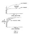
- Figure 1 shows the result obtained by adjusting the input level of the signal fed to the loudspeaker on the basis of equalization test measurements made with a pink noise signal in equilibrium with the room as is the standard procedure followed almost universally by those engaged in the correction of room acoustic anomalies by frequency domain multi-band equalization.
- Fig. 1 It will be seen in Fig. 1 that increased input at high frequencies by an amount calculated to assure equality of level in the equilibrium state (during which the test of the system is made), will lead to a severe anomaly during the onset period.
- the duration of such anomaly is directly related to the onset time of the room or, more correctly, to the difference between onset times at high and low frequencies and the overall onset time characteristic.
- the nature of the anomaly is such that early arriving sound at the listener's location will contain far too high an amount of high frequency energy.
- transient signals such as the attack occurring at the initial sounding of a musical instrument, will have too much high frequency energy, distorting the sound quality and seriously affecting the perceived realism of reproduced sound.
- the present invention is intended to overcome the foregoing problems through a relatively inexpensive, novel equalization system that directly synthesizes the required filter in the time domain, without need for either measurement or computation of the system transfer function or power spectrum.
- the filter synthesis is accomplished without requiring any technical knowledge or skill on the part of the system user.
- the correction achieved by such filter can be precise within a bandwidth of as small as 1/100 octave or even smaller.
- the invention in sum, solves acoustic problems that heretofore have been considered beyond the control of sound engineers.
- a primary object of the present invention is therefore to provide an improved audio equalization system.
- an object of the present invention is to provide an equalization system operating in the time rather than the frequency domain, thereby permitting solution of a number of the problems found in the prior art.
- the equalizing filter means includes a filter operative in the time domain; to provide such a system in which the filter is a discrete-time filter; to provide such a filter means which includes a digital computer programmed to generate coefficients for a discrete-time filter to be used for equalizing the perceived acoustic output of a sound reproduction system including an electroacoustic transducer disposed in a predetermined location in a particular environment; to provide such a filter means in which the digital computer is also programmed to perform discrete-time filtering of the electrical audio- frequency signals intended to be equalized, all in accordance with the coefficients previously generated; to provide such a filter means which can readily correct for acoustic anomalies which are linearly or irregularly spaced in the frequency domain; to provide such an equalizing system in which the digital computer is programmed to design matched filters to thereby alter the spectrum of an input signal to approximate that of a selected reference signal; and to provide such an equalizing system which can correct selective
- Yet another object of the present invention is to provide time-domain equalization which does not create an anomaly in reproduction related to the onset time of the room in which reproduction takes place, and therefore makes possible the rendering of natural and accurate augmentation of sound level.
- apparatus for modifying the audio response of a sound reproduction system particularly in the form of an improved audio equalizer comprising a discrete-time filter connected in the sound reproduction system.
- Means are provided for introducing an electrical test signal into a first point in the sound reproduction system, typically at the input of an elctroacoustic transducer.
- Means, such as a microphone are provided for detecting at a predetermined location the acoustic output produced by the transducer of the sound reproduction system in response to the test signal.
- the equalizer includes means for generating a sampled sequence of signals from the detected acoustic output of the sound reproduction system.
- Means are provided for generating from the sequence of signals, coefficients of the discrete-time filter and the tap locations or time slots of the respective coefficients. Means are also included for storing those coefficients and time slots or locations in appropriate order together with the addresses at which they are stored.
- the term "sound reproduction system” is intended to be construed broadly enough to include a system embracing a signal path between means which detects the original audio signal to be reproduced and the ultimate listener, at least part of that path being an electrical signal channel. It will be apparent that this definition is intended to include, as part of the total signal path, typical components such as recording and broadcast apparatus, turntables, pick-up cartridges, tuners, amplifiers, loudspeakers and other components that affect the signal transmission along the path, as well as other elements such recording and broadcast media and the enclosure into which the final reproduced sonic pressure waves are radiated.
- discrete-time filter is intended to refer to a finite impulse response (FIR) filter whether digital or analog in structure and operation.
- FIR finite impulse response
- Such a discrete-time filter is typified by a tapped delay line in which the signal level from each tap is weighted by some predetermined value, for example of an output resistor in analog filters of this type.
- the means for generating the coefficients and tap locations of a finite impulse response filter is conveniently a digital computer programmed to convolve the digitized, perceived test signal with a target spectrum signal to generate the filter coefficients and tap locations.
- the target spectrum may be that of the detected signal itself, in which case the convolution is akin to an autocorrelation function, or can be some other target spectrum which may or may not be functionally related to the test signal, in which instance the convolution is akin to a cross-correlation function.
- a preferred convolution operation is one which generates discrete-time filter coefficients and time locations on the basis of the detected acoustic output of the sound reproduction system, using an adaptive least mean square error algorithm.
- a communications link is provided between the output of the microphone means and the input of the means for generating the time-sampled sequence of signals.
- This communications link is preferably electro-optical and includes manually operable means coupled to the microphone means and communications link for initiating generation of an optical carrier.
- the means for providing the test signal is actuated to provide the test signal responsively to detection of the optical carrier by a sensor connected to the sound reproduction system.
- the means for generating the time-sampled sequence includes time-sampling means and an analog-to-digital converter. Switching means are provided for alternatively connecting the input of the time-sampling means between (1) a source of signals to be equalized by the equalizing system, and (2) the communications link to receive signals transmitted from the output of the microphone means.
- Means are also provided operative initially upon provision of the test signal, for actuating the switching means so as to connect electrical signals from the communications link to the input of the time sampling means, and operative after generation and storage of the coefficients and time locations, for actuating the switching means so as to connect the source of signals to be equalized to the input of the time-sampling means, the digital computer means being also programmmed to then convolve the stored coefficients at their respective time locations with digital signals received from the time-sampling means, thereby linearly filtering such digital signals to achieve equalization.
- the time locations of the coefficients are not necessarily contiguous with one another but may be irregularly spaced apart in time. Such coefficents and their relative location in time (i.e. their time locations) will be in the specification and claims hereinafter referred to simply as coefficients or set thereof, and it will be seen that such set defines the impulse response of the filter.
- FIG. 2 there is shown an equalizing system of the present invention embodied for the sake of illustration only, in a single audio channel system, it being understood that the principles of the present invention are equally applicable to multichannel systems such as stereophonic systems.
- the embodiment of Fig. 2 comprises input terminal 20 at which an audio signal to be equalized is applied, typically from a preamplifier or the like.
- Terminal 20 is couplable, through operation of switching means 22, to input terminal 24 of an equalizing circuit.
- terminal 24 can be connected through operation of switching means to terminal 26.
- Terminal 24 is connected to two parallel channels, one a high frequency path, the other providing a path for low frequencies for which equalization is to be provided.
- the bandwidth of the low frequency path is about 20 to about 1000 Hz inasmuch as the major anomalies in room acoustics occur within this frequency range, but it is to be understood that the invention is not limited to any particular bandwidth and can be applied, for example, to the entire broadband audio input spectrum to the system.
- the low frequency path therefore includes an appropriate low-pass signal filter 32 having its input connected to terminal 24.
- Filter 32 serves as an anti-aliasing filter, attenuating signal components above the Nyquist frequency to insure that no aliasing errors occur during the sampling process.
- Low-pass filters are well known in the art and need not be described further herein.
- sample-and-hold circuit 34 a well known analog signal storage device which permits readout and storage of a value x(tl) of a variable voltage x(t) at a specified sampling time t l .
- sample-and-hold circuit 34 a well known analog signal storage device which permits readout and storage of a value x(tl) of a variable voltage x(t) at a specified sampling time t l .
- the latter can be a Model SHC 298 AM currently obtainable from Burr-Brown Research Corporation, Arlington, Arizona.
- analog-to-digital converter 36 the latter typically being an AD 574 integrated circuit obtainable from Analog Devices of Norwood, Mass.
- the output of converter 36 is connected as a data input of microcomputer circuit 37 which is basically a microprocessor with memory.
- Circuit 37 can be either an analog computer, in which instance no input A/D or output D/A converter is required, or a digital computer as will be described for purposes of illustration herein.
- the central processor unit 90 and a random access memory of circuit 37 are exemplified by a TMS 9995 chip obtainable from Texas Instruments of Dallas, Texas. The ancillary parts and operation of circuit 37 will be described later here.
- the processed digital signals are fed to digital-to-analog converter 38, for example a Model DAC 80 from Burr Brown Research Corporation.
- the output of converter 38 is connected to the input of low-pass reconstruction filter 40 which serves to remove high frequency components introduced in the reconstruction of the digital signals to analog signals by converter 38.
- the output of filter 40 is connected to amplitude equalizer circuit 42, the latter serving to correct the sinx/x rolloff introduced by converter 38.
- Gain control circuit 44 is connected to control the amplitude of the output signal from circuit 42 and may be designed to provide a fixed gain, or to be user- adjustable or to be under the control of micropro- computer circuit 37.
- the low frequency channel terminates by connection of the output of gain control circuit 44 to the input of analog summing device 46, typically a well-known operational amplifier.
- the high-frequency channel is formed of high-pass analog filter 50 having its input connected to terminal 24 and its output connected to delay equalization circuit 52.
- the latter typically is an all-pass, active filter designed to have a phase response which complements that of the low pass channel.
- the output of circuit 52 is connected as another input to summing device 46.
- the output of the latter is connected through power amplifier 56 to the drivers of loudspeaker system 58.
- test signal generator 60 for example a well known white noise generator, for providing a signal over a wide bandwidth with a constant power spectrum.
- generator 60 may be a circuit including a digital-to-analog converter and reconstruction filter, for generating a test signal from digital data or test spectrum, typically stored for example in a memory device within microcomputer 37.
- Generator 60 may be manually turned on and off, but in a preferred form is electrically coupled (as shown by lead 61) to microcomputer 37 so that the generator can be turned on and off on command from the microcomputer.
- the output of generator 60 is connected to the input of low-pass filter 62 which serves to remove unwanted high frequency components, typically those above 1000 Hz for this embodiment.
- the output of filter 62 is connectable to the input to power amplifier 56 by switching means 64 operable in tandem with switching means 22 by relay 87, as will be hereinafter described.
- the apparatus of Fig. 2 also comprises microphone 70, the output of which is coupled to the input of high pass filter 71 which serves to remove extraneous noise.
- the output of filter 71 is connected to the input of modulator circuit 72.
- modulator circuit 72 includes typically an oscillator to establish a carrier frequency higher than the bandwidth over which equalization is to occur.
- the microphone output signal typically is used to modulate the carrier signal from the oscillator i.e. in frequency, amplitude, pulse width or the like.
- the modulated electrical signal is then introduced into power circuit 74, the output of the latter being coupled to drive light-emitting diode (LED) 76 to follow the modulations of the signal from modulator circuit 72.
- LED 76 preferably, for purposes of the present invention, emits in the infra-red. Of course, other modulation schemes, well known in the art, may also be used. It will be apparent that the combination of microphone 70, modulator circuit 72, driver circuit 74 and LED 76 serve to detect and convert the acoustical signals received by microphone 70 into corresponding light signals radiated by LED 76 within a narrow light frequency range.
- Power source 78 is connectable through manually operable switch means 80 for powering microphone 70 and circuits 72 and 74.
- the entire ensemble of microphone 70, circuits 72 and 74, LED 76, power source 78 and switch 80 are preferably packaged as a unit physically independent of and unconnected with any of the other equipment, so as to be capable of being hand-held and carried about a room to any desired location by a listener.
- the apparatus of Fig. 2 further comprises photoelectric detector means 82 capable of being responsive to light emitted by LED 76, typically by having a spectral response to only light within the frequency range generated by LED 76. Such selective response can readily be obtained, if desired, by an appropriate light filter 84 to screen photoelectric means 82.
- the output of the latter is connected to known demodulator circuit 86 which serves to demodulate or to recover the original electrical signal (or a signal proportional thereto) generated by microphone 70.
- the output of demodulator circuit 86 is connected to terminal 26.
- the latter in turn is connectable to terminal 24 by operation of switch 22 which, although the latter may be manually controlled, in the preferred embodiment is operable by a relay 87 responsive to an initial signal from demodulator 86.
- Relay 87 is typically of the type which, after a predetermined delay, opens and permits switch 22 to return to its normal position wherein terminal 24 is connected to terminal 20. As earlier indicated, relay 87 also serves to operate switch 64 so that the output of filter 62 is respectively connected to the input of amplifier 56 and the output of amplifier 46 is disconnected from the input to amplifier 56 simultaneously with connection of terminal 24 to terminal 26.
- such communications link may simply be in the form of electrically conductive wiring, thereby replacing the modulation/demodulation circuits with a sigle amplifier.
- Microcomputer circuit 37 includes central processing unit 90 and a read-only memory (ROM), in general both erasable and programmable, exemplified by a TMS 2532 EPROM chip from Texas Instruments, Dallas, Texas.
- the read-only memory is divided into two or more sections.
- One such section is filter synthesis program ROM 92 for storing a program for analyzing an array of digital signal values which constitute the output of converter 36 when the test signal generator 60 is providing the acoustic input to the system, and for computing the digital values of the coefficients and tap locations of a finite impulse response filter.
- Another section is filtering program ROM 94 for storing a program which convolves the computed set of coefficients with the digitized samples of the audio signal provided at terminal 20.
- ROM 36 can be another TMS 253R EPROM if desired.
- Microcomputer circuit 37 also includes random-access memory (RAM) means in the form of coefficients RAM 98 for storing the set of filter coefficients computed by CPU 90, RAM 98 typically being the memory included in the TMS 9995 integrated circuit above-identified.
- RAM random-access memory
- Circuit 37 also includes, in the form of TMS 4016 RAMs from Texas Instruments, analysis data RAM 100 for storing the samples of the digitized test signal received by microphone 70 and transmitted to terminal 24, and RAM 102, a type of scratch-pad memory for storing temporary data created during convolution operations or in operations performed in creating the filter.
- loudspeaker 58 In operation, to equalize loudspeaker 58 with regard to any desired location of a listener in a room containing the loudspeaker, it is first necessary to generate or compute an equalization filter. Thus, the listener disposes himself at that desired locale in the room and manually operates switch 80 to power LED 76, directing a light beam from LED 76 toward detector 82. Initially unmodulated radiation from LED 76 as detected by photoelectric detector 82 produces an initial signal which operates relay 87 to close switch 22 so as to connect terminals 26 and 24 and closes switch 64 to connect the output of test signal generator 60 to amplifier 56 and disconnect amplifier 46 from amplifier 56.
- the initial signal then serves to trigger over line 104, microcomputer 37 to initiate execution of the synthesis program and to initiate operation of generator 60 to generate its test signal or alternatively a signal having its samples stored in ROM 96, all resulting in the subsequent production of a corresponding acoustic test signal from speaker 58.
- That test signal picked up by microphone 70 at the desired location and converted to an optical waveform, is transmitted on the optical link between LED 76 and photoelectric detector 82, converted back into an electrical waveform, and filtered in filter 32 to provide signals typically below about 1kHz and introduced into sample-and-hold circuit 34.
- the choice of a band-pass of from 20Hz to 1 Khz is exemplary; the present invention is not particularly limited to any particular bandwidth, nor to the use of any specific input filters, although the major problems in equalization tend to occur with respect to signals below about 1 Khz.
- the signal introduced into sample-and-hold 34 can be the full range of input audio frequencies, assuming that sample-and-hold circuit 34 possess an appropriate sampling rate.
- the system need not include filter 32, or for that matter the high frequency path established by filter 50 and delay circuit 52, inasmuch as microcomputer 37, if of sufficient capacity, can be used to accomplish the desired input filtering and crossover digitally.
- microcomputer 37 if of sufficient capacity, can be used to accomplish the desired input filtering and crossover digitally.
- additional arithmetic and/or memory units can be coupled to microcomputer 37 to increase the operating capacity of the latter, if desired.
- sampling rate of sample-and-hold circuit 34 is established by a clock (not shown), that sampling rate being a function of the repetition rate of the clock.
- the sampling rate as well-known in accordance with the Nyquist criterion, must be at least double the highest frequency of interest. Thus typically a sampling rate of 2.5 kHz will sample an exemplary 20Hz to 1 Khz audio frequency range passed by filter 32.
- sample-and-hold circuit 34 If the data signal introduced into sample-and-hold circuit 34 has any frequency components higher than half the sampling rate it cannot be accurately reconstructed subsequently by digital-to-analog converter 38.
- the sampling system will generate an aliased signal component, the frequency of which is the difference between the frequency of the original input signal component and the sampling rate or frequency.
- anti-aliasing filter 32 at the input of circuit 34 serves to attenuate very sharply any signal over half of the sampling rate.
- the anti-aliasing filter can be made relatively inexpensively and more importantly, will exhibit a relatively negligible phase shift.
- the low-pass filtered electrical form of the test signal is then sampled in sample-and-hold circuit 34 to provide a sequence in time of analog samples of the signal amplitude, each sample having substantially the same time duration and separated in time from the others according to the sampling rate used.
- These analog samples are then fed to analog-to-digital converter 38 where the amplitude of each sample is translated or converted into a digital value, typically expressed as a binary number.
- the purpose of converting the samples to digital form is so that they can be processed by the digital techniques employed by microcomputer 37.
- the digitized samples are transferred to microcomputer 37 and initially stored in analysis data RAM 100 under control of the program in synthesis program ROM 92.
- any linear network or system with input and output terminals can be characterized by describing its properties in terms of either the "frequency domain” or the "time domain".
- a "frequency domain” description of a system is one in which amplitude and phase of an output signal from the system are represented as a function of signal frequency. In the frequency domain, one does not deal explicitly with time functions but instead, for example, with Fourier or Laplace transforms and the like, which are functions of frequency.
- the "time domain” description is one in which the amplitude of the output signal of the system is represented purely as a function of time.
- time domain description is contained in the impulse response of the system to an input impulse which ideally is of infinitesmal duration and unit amplitude. It is recognized that the time domain and frequency domain systems are mathematically related, and typically one may be transformed into the other by known transformations. For example, in the frequency domain the transfer function of the network or system can be described as the Fourier transform of its impulse response.
- the present invention operates in the time domain, and employs discrete-time filter means specially adaptable for equalizing the sound arriving at a listener's selected location.
- the present invention samples the sound signals in the time domain, a process which translates them into numerical values, and then the latter are convolved with a set of predetermined filter coefficients.
- a sampled and digitized signal of speech, music or any other time-varying quantity can be considered as a sequence of impulses of varying amplitude and polarity, the magnitude and polarity of any impulse corresponding to the magnitude and polarity of the original signal wave form at the exact time of sampling.
- a digital representation of the impulse response of a filter after the impulse response has been sampled and digitized, consists generally of a finite sequence of numbers, the numbers correponding to amplitude during consecutive sampling periods, i.e. spaced equally apart in time. Each such number in the series bears a fixed proportional relation to the others. Any convenient numerical scale can be used to represent the filter impulse response, which is fully defined by this proportional relation.
- the absolute values of the numbers in the sequence are exactly proportional to the magnitude of the applied impulse, and it is common to assume in such descriptions-that this magnitude has a numerical value of 1.0, with the impulse designated the unit impulse, (n), although clearly one can arbitrarily scale the numbers of the sequence.
- Convolution of a digital filter impulse response and a sampled, digitized signal will thus create a sequence of sums of scaled filter impulse response.
- the result of the convolution process is an output signal as described in the following exemplary way, simplified for purposes of exposition.
- the values of the filter impulse response need not correspond to the physical response of any existing analog filter or system, but can be simply any sequence of numbers designated a filter. It is therefore possible to create a digital filter which could not be synthesized with analog filter components, such as a sparsely populated filter i.e. one in which a section of the filter impule response is zero. Reasons why such a filter is desirable will be discussed later herein.
- the filter numbers are ordinarily referred to as "coefficients".
- a conventional mathematical expression for the convolution process derives the final output signal values one at a time by summing the products of previous consecutive input signal values and the coefficients:
- the input signal x(n) for exemplary purposes here consists of the values 2 and -2, beginning at time zero and alternating for a long period of time, or
- linear prediction The method of time series analysis known as linear prediction is a technique which has been widely applied in speech analysis and synthesis, geophysics and other fields.
- a detailed review of the subject is given in a paper entitled "Linear Prediction: A tutorial Review", by J. Makhoul, Proc. IEEE, Vol. 63, pp. 561-580, April, 1975.
- COVAR covariance method
- AUTO autocorrelation method
- Equations (4) and (5) represent the following procedure: a filter is convolved as set forth in equation (1) with a sampled input signal, for a single iteration only; the result is taken as the error signal e(n), the difference between x(n) and its "predicted value" represented by the summation term in equation (4).
- Equation (5) represents the subsequent adjustment or adaptation of the coefficients numbered 1 through m-1, by adding to each coefficient the product obtained by multiplying e(n) by x(n-j), the jth signal sample counting back from the present, and by p, the latter being a number selected to give the most rapid and accurate convergence of the coefficient values to a final and stable form. In practise the value of p will be adjusted in the course of the adaptation to improve convergence.
- equation (1) can be said to obscure the intuitive significance of a convolution as a repeated multiplication and addition of the filter impulse response, equations (2) and (3), although simple and elegant, do not immediately suggest their profound significance.
- the synthesis of the filter coefficients is, in fact, a process of detecting correlations or order in the input signal, the value of the coefficients tending toward zero as the disorder of the input signal increases.
- the correlations will be seen to arise out of the disturbances to the test signal created by, for example, acoustic reflections from the room boundaries and contents.
- a filter complementary preferably to the greatest anomalies appearing in the test signal as perceived by a listener.
- one processes in microcomputer 37 a sequence of N digitized test signal samples from microphone 70 as stored in RAM 100.
- the length of the sequence N is preferably a number small enough to permit the microcomputer to perform the processing with reasonable constraints on memory size and execution time, yet large enough to provide an accurate representation of the anomalies to be corrected.
- the process in effect seeks correlations introduced into the sequence by the electromechanical properties of the loudspeaker system and by acoustical phenomena such as reflections and diffractrion.
- This correlation information is used to produce the desired correction filter used for equalization.
- a simplified example of the numerical process of convolution is provided hereinafter in connection with preparation of the filter, but such numerical process is substantially illustrative of the use of the filter to provide equalization as well.
- adaptive linear prediction is initially performed on the N data samples with a prediction filter of M contiguous tap locations, where for example M is selected to be 128.
- a subset is chosen, (the subset preferably being a given submultiple of M (e.g. 112 of 64), which subset contains the 64 largest or most important coefficients of the original set. All other coefficients of that subset of 64 are then set to zero and the selected set is then again subjected to the adaptive process to establish a new set of 64 coefficients. These latter in turn are compared with one another to select the next subset (32) of coefficients using the same criteria for selection.
- the new subset is again processed as above described and the iterative process is continued until a final filter has been designed with a desired number of non- zero coefficients.
- the coefficients and their respective tap locations are then stored in RAM 98 for use in correcting or equalizing the audio signal intended to be applied at terminal 20.
- Fig. 4a Shown in Fig. 4a is an exemplary flow diagram from which one can readily prepare a computer program to control the operation of microcomputer 37 to effect the objects of the present invention.
- Subroutine A shown in Fig. 4b, partly in Fortran notation, sets forth a flow diagram illustrating the formation of a digital filter according to the principles above described, while Fig. 4c shows Subroutine B which is used to apply the computer filter to equalization of audio signals also as earlier described herein.
- test signal In evaluating the response of, an electroacoustic system, the choice of test signal is extremely important, and this is no less true in the case of the present invention.
- the test signal should have as little auto-correlation as possible, and should allow the system to produce results to the desired degree of accuracy.
- the better test signal of this kind must also take into account the length of the data upon which the filter will be based.
- An optimal test signal for purposes of the present invention is a numerical sequency of the kind termed a quadratic-residue sequence, known and described in the literature of number theory by A. M. Legendre and C. F. Gauss, and also employed in acoustical applications to architectural design by M. R. Schroeder (J. Acoust. Soc. Am., 65 (4), April, 1979, "Binaural Dissimilarity and Concert Halls").
- N An approach to the proper selection of N is indicated by the need to include enough data samples so that the repetition rate is at at least below the lowest frequency of interest.
- a sampling rate of 2.0 kHz for example, a signal band limited (theoretically) to 1.0 kHz is dictated, less in practice.
- a lower limit of 20 Hz would be considered reasonable for music transmission. Since one wave at 20 Hz corresponds to a period of 50 milliseconds or 100 samples, and one might allow a factor of 2 for flexibility in system design, the prime 257 would be a good candidate for N.
- the test signal in digital form is preferably stored in target data ROM 96, and thus can be modified as desired. While that test signal optimally exhibits a uniform power spectrum, for certain purposes other target spectra may be desirable.
- the target spectrum may be white noise or a quadratic-residue sequence modified by reflections within a specified concert hall.
- Production of a filter from such a target spectrum according to the present invention and convolution of that filter with an audio signal which is desired to be equalized will endow equalization with characteristics of the audio response of that concert hall.
- the filter can be designed to alter the spectrum of an input audio signal spectrum to cause the latter to approximate virtually any type of signal spectrum desired, when reproduced by the loudspeaker of the system.
- a delay time, t d is established equal to the early portion of the arriving sound as defined by the user, and the coefficient values are set to a fixed value of zero for all sample periods up to that time. Only after t d are the time and adaptation steps allowed to operate.
- a filter will be synthesized based only on the correlation between the present signal and signal events some time in the past, i.e. the system will ignore any correlation between recent signal information and the present value.
- the developed filter will be determined entirely by detected correlation between a signal arriving at time t d and signal samples which arrived at a prior time t d -t' and earlier. Control of the duration of the excluded period can be provided by a number of simple known techniques such that the user of such an equalizer may readily select the portion of the reverberant or later arriving sound for equalization.
- the filter should equalize out components due to the later portions of the system impulse response only, i.e. the diffuse field corresponding to reflected energy.
- the filter should leave unaffected the early information reaching the listener, in order to maintain as nearly as possible the purity of the sound of the direct radiation from the loudspeaker.
- a first step prior to execution of the initial convolution is the insertion, as part of the system impulse response, of an ordinal zeroth coefficient with an assigned value which results in a corresponding zeroth coefficient of unit cardinal value in the filter derived by this method.
- the next step is the use of additional coefficients of cardinal value zero immediately following the zeroth coefficient, these additional coefficients replacing the same number of samples of the original impulse response which represent the time delay desired.
- the purpose of each of these steps is as follows.
- the zero cardinal value coefficients in the leading places serve to delay any output from the filter until the arrival of the later information at the listener's location.
- the unity coefficient in ordinal place zero appears again in the derived filter automatically, and provides an unmodified output of the direct signal (each sample simply multiplied by 1).
- Such early sound time interval is preferably specified in units of time, to indicate the start of the period when the direct radiation is first mixed with the reflected or reverberant sound when the acoustic field is thought to become diffuse, or alternatively in units of distance, where the path length of the first reflection is calculated by the user.
- a simple arithmetic circuit or an algorithm executed by microcomputer 37 then serves to convert the user's setting of a dial (e.g. calibrated in milliseconds or meters) into an integer representing the number of early samples to be truncated or skipped, i.e., assigned cardinal values of zero.
- a counter inserted into the circuit of Fig.
- the counter can be set to provide an inhibit signal which instructs microcomputer 37 to store a unit cardinal value for the zeroth coefficient upon count of the first sample and to permit the determination of no other coefficients for the filter until the time period set by the manual control has expired.
- a simplified system impulse response h(n) is illustrated by the sequence (here merely exemplary)
- a room impulse b(n) defined as is simply here represented in Fig. 5b as the direct signal or unit sample at time zero, and a reflective spike of value a (I i ⁇ 1) at a time T , T being greater than zero.
- a room impulse b(n) defined as is simply here represented in Fig. 5b as the direct signal or unit sample at time zero
- a reflective spike of value a (I i ⁇ 1) at a time T being greater than zero.
- T the time delay introduced by the path distance from the acoustic source to receiver has been ignored.
- the response f(n) of the system in the room is obtained by convolving h(n) with b(n) as both are above defined for purposes of this example:
- f(n) is an early or immediate sequence with the values 3, -2, 1 representing the direct field, and a much later sequence of values 1.5, -1, 0.5 representing the diffuse field.
- any signal X(n) passing through the system f(n) will produce an output signal:
- the invention may also be employed to create a filter which will convert audio spectrum B to some audio target spectrum A.
- a filter which will convert audio spectrum B to some audio target spectrum A.
- the behaviour of an adaptive LMS algorithm in the context of the present invention is to produce a filter which will maximally whiten the output of the sound reproduction system. Consequently, the introduction of a test signal with target spectrum A into an equalizer of the present invention before adaptation of the latter, i.e. for purposes of creating a filter, in accordance with the teachings hereinbefore set forth will produce an output signal with a white noise spectrum W.
- the transfer function of the equalizer following such adaptation is W/A. If now one introduces into the thus adapted equalizer an input audio signal with a spectrum B, the output signal must have a spectrum characterized as BW/A. The latter signal, when used as the input test signal to another similar equalizer before adaptation of the latter, will generate a filter with a transfer function of WA/WB, or A/B. If one uses an audio signal with a spectrum B as the audio input to an equalizer with a filter having a transfer function A/B, then the output signal from that equalizer must have the characteristics of the target spectrum A.
- Fig. 6 Operation of the invention in comparison with a prior art equalization system is shown in Fig. 6 wherein there is shown in solid line, the normal frequency response of a model AR93 loudspeaker (a product of Acoustic Research, a division of Teledyne, Inc., Norwood, Mass.), the finely dotted line showing the response of the same speaker filtered by one of the better of the prior art equalization systems using fixed frequency bands, and the heavily dotted line shows the frequency response obtained by filtering according to the principles of the present invention employing a 16 coefficient filter operating between 20Hz and 1 Khz.
- the advantages of the present invention, particularly in reducing the greatest deviation from a flat response are immediately apparent.
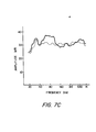
- Fig. 7 Operation of the present invention in improving the perceived response of loudspeakers generally is shown in Fig. 7 wherein Figs. 7A, 7B and 7C are respectively illustrative of the operation of a Model L50 speaker from James B. Lansing Sound, Inc., Los Angeles, California, a Model 301 speaker from Bose Corp., Framingham, Mass., and a Model 105 speaker from KEF Electronics, Ltd., Kent, England.
- the unfiltered response of each speaker is shown in solid line and the response following filtering according to the principles of the present invention with a 16 coefficient filter between 20Hz and 1 KHz, is shown in broken line.
Landscapes
- Physics & Mathematics (AREA)
- Engineering & Computer Science (AREA)
- Acoustics & Sound (AREA)
- Signal Processing (AREA)
- Circuit For Audible Band Transducer (AREA)
- Tone Control, Compression And Expansion, Limiting Amplitude (AREA)
- Stereophonic System (AREA)
- Measurement Of Mechanical Vibrations Or Ultrasonic Waves (AREA)
- Filters That Use Time-Delay Elements (AREA)
Applications Claiming Priority (2)
| Application Number | Priority Date | Filing Date | Title |
|---|---|---|---|
| US06/378,009 US4458362A (en) | 1982-05-13 | 1982-05-13 | Automatic time domain equalization of audio signals |
| US378009 | 1999-08-19 |
Publications (2)
| Publication Number | Publication Date |
|---|---|
| EP0094762A2 true EP0094762A2 (de) | 1983-11-23 |
| EP0094762A3 EP0094762A3 (de) | 1985-09-11 |
Family
ID=23491360
Family Applications (1)
| Application Number | Title | Priority Date | Filing Date |
|---|---|---|---|
| EP83302496A Withdrawn EP0094762A3 (de) | 1982-05-13 | 1983-05-04 | Automatische Zeitbereichs-Ausgleichsvorrichtung für Audiosignale |
Country Status (3)
| Country | Link |
|---|---|
| US (1) | US4458362A (de) |
| EP (1) | EP0094762A3 (de) |
| JP (1) | JPS5932299A (de) |
Cited By (17)
| Publication number | Priority date | Publication date | Assignee | Title |
|---|---|---|---|---|
| EP0145997A2 (de) * | 1983-11-28 | 1985-06-26 | Peter Michael Dipl.-Ing. Pfleiderer | Einrichtung zur Kompensation von Wiedergabefehlern eines elektroakustischen Wandlers |
| EP0168078A1 (de) * | 1984-06-08 | 1986-01-15 | Koninklijke Philips Electronics N.V. | Anordnung zur Umwandlung eines elektrischen Signals in ein akustisches Signal oder umgekehrt und ein nichtlineares Netzwerk zur Anwendung in dieser Anordnung |
| EP0219865A2 (de) * | 1985-10-23 | 1987-04-29 | Matsushita Electric Industrial Co., Ltd. | System und Verfahren zum Überwachen der Tonqualität |
| EP0288159A2 (de) * | 1987-03-23 | 1988-10-26 | Matsushita Electric Industrial Co., Ltd. | Digitales Entzerrergerät für getrennte Phasen- und Amplitudenmodifikation |
| WO1990000851A1 (en) * | 1988-07-08 | 1990-01-25 | Adaptive Control Limited | Improvements in or relating to sound reproduction systems |
| WO1992010876A1 (en) * | 1990-12-11 | 1992-06-25 | B & W Loudspeakers Ltd. | Compensating filters |
| GB2221595B (en) * | 1988-07-08 | 1992-09-30 | Univ Southampton | Improvements in or relating to sound reproduction systems |
| EP0508392A2 (de) * | 1991-04-09 | 1992-10-14 | Jbl Incorporated | Schaltungsanordnung zur Korrektur des linearen und nichtlinearen Übertragungsverhaltens elektroakustischer Wandler |
| EP0529158A1 (de) * | 1989-11-14 | 1993-03-03 | Lovejoy Controls Corporation | Vorrichtung zur Steuerung des Klunges |
| EP0556867A1 (de) * | 1987-03-23 | 1993-08-25 | Matsushita Electric Industrial Co., Ltd. | Digitales Entzerrungsgerät mit Möglichkeit zur getrennten Modifikation der Phasen- und Amplitudencharakteristik |
| EP0748143A2 (de) * | 1986-03-27 | 1996-12-11 | SRS LABS, Inc. | Stereoeffekt-Verbesserungssystem |
| GB2403360A (en) * | 2003-06-28 | 2004-12-29 | Zarlink Semiconductor Inc | Reduced complexity filter implementation |
| US7907736B2 (en) | 1999-10-04 | 2011-03-15 | Srs Labs, Inc. | Acoustic correction apparatus |
| US7987281B2 (en) | 1999-12-10 | 2011-07-26 | Srs Labs, Inc. | System and method for enhanced streaming audio |
| US8050434B1 (en) | 2006-12-21 | 2011-11-01 | Srs Labs, Inc. | Multi-channel audio enhancement system |
| GB2485510B (en) * | 2009-09-15 | 2014-04-09 | Hewlett Packard Development Co | System and method for modifying an audio signal |
| CN109931967A (zh) * | 2019-02-21 | 2019-06-25 | 电子科技大学 | 一种光电探测器频率响应测量的频率配置方法 |
Families Citing this family (83)
| Publication number | Priority date | Publication date | Assignee | Title |
|---|---|---|---|---|
| NL8300671A (nl) * | 1983-02-23 | 1984-09-17 | Philips Nv | Automatisch egalisatiesysteem met dtf of fft. |
| JPH0663777B2 (ja) * | 1984-03-24 | 1994-08-22 | ソニー株式会社 | イコライザ装置 |
| DE3580402D1 (de) * | 1984-05-31 | 1990-12-13 | Pioneer Electronic Corp | Verfahren und geraet zur messung und korrektur der akustischen charakteristik eines schallfeldes. |
| US4631749A (en) * | 1984-06-22 | 1986-12-23 | Heath Company | ROM compensated microphone |
| US4611343A (en) * | 1984-06-29 | 1986-09-09 | Heath Company | Audio spectrum analyzer operable in a difference mode |
| JPS61108289A (ja) * | 1984-10-31 | 1986-05-26 | Pioneer Electronic Corp | 自動音場補正装置 |
| JPS61108213A (ja) * | 1984-10-31 | 1986-05-26 | Pioneer Electronic Corp | オ−トグラフイツクイコライザ |
| US4698680A (en) * | 1985-12-24 | 1987-10-06 | Rca Corporation | Digital correlation apparatus as for a television deghosting system |
| US4852176A (en) * | 1986-05-12 | 1989-07-25 | Truhe Jr Joseph V | Continuous differential signal equalizer |
| US4823391A (en) * | 1986-07-22 | 1989-04-18 | Schwartz David M | Sound reproduction system |
| JP2681349B2 (ja) * | 1986-08-08 | 1997-11-26 | ヤマハ株式会社 | スピーカ再生装置 |
| US4785475A (en) * | 1987-01-29 | 1988-11-15 | Eugene Rimkeit | Apparatus and method for equalizing a soundfield |
| US4955058A (en) * | 1987-01-29 | 1990-09-04 | Eugene Rimkeit | Apparatus and method for equalizing a soundfield |
| JP2646210B2 (ja) * | 1987-05-27 | 1997-08-27 | ヤマハ株式会社 | 電気音響的残響支援装置 |
| US4811097A (en) * | 1987-10-29 | 1989-03-07 | Videotek, Inc. | Video signal processor |
| US5014320A (en) * | 1988-05-25 | 1991-05-07 | Yamaha Corporation | Driving apparatus, and control information storage body and protection circuit therefor |
| JP2649948B2 (ja) * | 1988-06-21 | 1997-09-03 | 株式会社ザナヴィ・インフォマティクス | 電子グライコ付オーディオ装置 |
| JP2592955B2 (ja) * | 1989-04-04 | 1997-03-19 | 株式会社東芝 | プログラム自動生成装置 |
| WO1992005501A1 (en) * | 1990-09-21 | 1992-04-02 | Cambridge Signal Technologies, Inc. | System and method of producing adaptive fir digital filter with non-linear frequency resolution |
| US5272656A (en) * | 1990-09-21 | 1993-12-21 | Cambridge Signal Technologies, Inc. | System and method of producing adaptive FIR digital filter with non-linear frequency resolution |
| US5325435A (en) * | 1991-06-12 | 1994-06-28 | Matsushita Electric Industrial Co., Ltd. | Sound field offset device |
| IT1272418B (it) * | 1993-04-29 | 1997-06-23 | Alcatel Italia | Sistema per il trattamento di segnali affetti da errori di trasmissione |
| US5572443A (en) * | 1993-05-11 | 1996-11-05 | Yamaha Corporation | Acoustic characteristic correction device |
| KR0129989B1 (ko) * | 1993-06-30 | 1998-10-01 | 김광호 | 자동 음색 조정방법 및 장치 |
| US5386478A (en) * | 1993-09-07 | 1995-01-31 | Harman International Industries, Inc. | Sound system remote control with acoustic sensor |
| US5596650A (en) * | 1994-04-29 | 1997-01-21 | Audio Products International Corp. | Equalizing circuit for a loudspeaker system |
| US5727074A (en) * | 1996-03-25 | 1998-03-10 | Harold A. Hildebrand | Method and apparatus for digital filtering of audio signals |
| DE19740601C1 (de) * | 1997-09-16 | 1999-05-27 | Ralf Heinrich | Gerät zur Beeinflussung und Korrektur von Gruppenlaufzeitverzerrungen bei drahtgebundener Übertragung analoger und digitaler Signale |
| US6721428B1 (en) * | 1998-11-13 | 2004-04-13 | Texas Instruments Incorporated | Automatic loudspeaker equalizer |
| US6724706B1 (en) * | 1999-02-26 | 2004-04-20 | Matsushita Electric Industrial Co., Ltd. | Digital adaptive equalizer for different quality signals |
| US6518903B1 (en) * | 2000-01-06 | 2003-02-11 | International Business Machines Corporation | Analog-to-digital converter |
| US20040013272A1 (en) * | 2001-09-07 | 2004-01-22 | Reams Robert W | System and method for processing audio data |
| WO2002021505A2 (en) * | 2000-09-08 | 2002-03-14 | Neural Audio, Inc. | System and method for processing audio data |
| US6727428B2 (en) * | 2001-02-28 | 2004-04-27 | Thomas & Betts International, Inc. | Electrical outlet box |
| AT411415B (de) * | 2001-12-11 | 2003-12-29 | Bier Guenther Ing | Verfahren und vorrichtung zur erzeugung einer einem eingangs-datenstrom folgenden wechselspannung |
| US7483540B2 (en) * | 2002-03-25 | 2009-01-27 | Bose Corporation | Automatic audio system equalizing |
| FR2840759B1 (fr) | 2002-06-10 | 2004-07-23 | Cynove | Procede de sonorisation |
| US20050220959A1 (en) * | 2002-06-19 | 2005-10-06 | Ryuzo Ueno | Process for producing crystalline maltitol |
| JP4257079B2 (ja) * | 2002-07-19 | 2009-04-22 | パイオニア株式会社 | 周波数特性調整装置および周波数特性調整方法 |
| NZ542420A (en) * | 2003-03-10 | 2008-03-28 | Daniel E Cohen | Sound and vibration transmission pad and system |
| US7553288B2 (en) * | 2003-03-10 | 2009-06-30 | Cohen Daniel E | Sound and vibration transmission pad and system |
| US8668045B2 (en) * | 2003-03-10 | 2014-03-11 | Daniel E. Cohen | Sound and vibration transmission pad and system |
| US20040218701A1 (en) * | 2003-04-29 | 2004-11-04 | Prashant Singh | Protocol agnostic method for adaptive equalization |
| JP2005072676A (ja) * | 2003-08-27 | 2005-03-17 | Pioneer Electronic Corp | 自動音場補正装置及びそのためのコンピュータプログラム |
| US7929708B2 (en) * | 2004-01-12 | 2011-04-19 | Dts, Inc. | Audio spatial environment engine |
| JP4568536B2 (ja) * | 2004-03-17 | 2010-10-27 | ソニー株式会社 | 測定装置、測定方法、プログラム |
| US8284955B2 (en) | 2006-02-07 | 2012-10-09 | Bongiovi Acoustics Llc | System and method for digital signal processing |
| US10158337B2 (en) | 2004-08-10 | 2018-12-18 | Bongiovi Acoustics Llc | System and method for digital signal processing |
| US11431312B2 (en) | 2004-08-10 | 2022-08-30 | Bongiovi Acoustics Llc | System and method for digital signal processing |
| US10848118B2 (en) | 2004-08-10 | 2020-11-24 | Bongiovi Acoustics Llc | System and method for digital signal processing |
| US20060106620A1 (en) * | 2004-10-28 | 2006-05-18 | Thompson Jeffrey K | Audio spatial environment down-mixer |
| US7853022B2 (en) * | 2004-10-28 | 2010-12-14 | Thompson Jeffrey K | Audio spatial environment engine |
| KR101283741B1 (ko) * | 2004-10-28 | 2013-07-08 | 디티에스 워싱턴, 엘엘씨 | N채널 오디오 시스템으로부터 m채널 오디오 시스템으로 변환하는 오디오 공간 환경 엔진 및 그 방법 |
| US20060153404A1 (en) * | 2005-01-07 | 2006-07-13 | Gardner William G | Parametric equalizer method and system |
| US20070032895A1 (en) * | 2005-07-29 | 2007-02-08 | Fawad Nackvi | Loudspeaker with demonstration mode |
| WO2007016465A2 (en) * | 2005-07-29 | 2007-02-08 | Klipsch, L.L.C. | Loudspeaker with automatic calibration and room equalization |
| US7529377B2 (en) * | 2005-07-29 | 2009-05-05 | Klipsch L.L.C. | Loudspeaker with automatic calibration and room equalization |
| KR100677622B1 (ko) * | 2005-12-02 | 2007-02-02 | 삼성전자주식회사 | 오디오 파일의 이퀄라이저 설정 방법 및 이를 이용한오디오 파일 재생 방법 |
| WO2007076863A1 (en) * | 2006-01-03 | 2007-07-12 | Slh Audio A/S | Method and system for equalizing a loudspeaker in a room |
| US11202161B2 (en) | 2006-02-07 | 2021-12-14 | Bongiovi Acoustics Llc | System, method, and apparatus for generating and digitally processing a head related audio transfer function |
| US10848867B2 (en) | 2006-02-07 | 2020-11-24 | Bongiovi Acoustics Llc | System and method for digital signal processing |
| US10701505B2 (en) | 2006-02-07 | 2020-06-30 | Bongiovi Acoustics Llc. | System, method, and apparatus for generating and digitally processing a head related audio transfer function |
| US10069471B2 (en) | 2006-02-07 | 2018-09-04 | Bongiovi Acoustics Llc | System and method for digital signal processing |
| EP2025193B1 (de) * | 2006-05-17 | 2013-07-17 | Francesco Pellisari | Akustikkorrekturvorrichtung |
| US7845233B2 (en) * | 2007-02-02 | 2010-12-07 | Seagrave Charles G | Sound sensor array with optical outputs |
| US20090052701A1 (en) * | 2007-08-20 | 2009-02-26 | Reams Robert W | Spatial teleconferencing system and method |
| WO2009103832A1 (es) * | 2008-02-20 | 2009-08-27 | Manuel Benedito Lozano | Método de control y procesado de señales analógicas, digitales o una combinación de ambas |
| EP2545716B1 (de) * | 2010-03-12 | 2019-11-13 | Nokia Technologies Oy | Vorrichtung, verfahren und computerprogramm zur steuerung eines akustischen signals |
| US9094768B2 (en) | 2012-08-02 | 2015-07-28 | Crestron Electronics Inc. | Loudspeaker calibration using multiple wireless microphones |
| US8773793B1 (en) * | 2012-08-03 | 2014-07-08 | Western Digital Technologies, Inc. | Disk drive selecting target response based on identified response |
| US9250338B2 (en) | 2013-05-20 | 2016-02-02 | Teledyne Instruments, Inc. | Multilayer jacket for marine acoustic array applications |
| US9264004B2 (en) * | 2013-06-12 | 2016-02-16 | Bongiovi Acoustics Llc | System and method for narrow bandwidth digital signal processing |
| US9883318B2 (en) | 2013-06-12 | 2018-01-30 | Bongiovi Acoustics Llc | System and method for stereo field enhancement in two-channel audio systems |
| US9906858B2 (en) | 2013-10-22 | 2018-02-27 | Bongiovi Acoustics Llc | System and method for digital signal processing |
| US10639000B2 (en) | 2014-04-16 | 2020-05-05 | Bongiovi Acoustics Llc | Device for wide-band auscultation |
| US10820883B2 (en) | 2014-04-16 | 2020-11-03 | Bongiovi Acoustics Llc | Noise reduction assembly for auscultation of a body |
| EP3146704A4 (de) | 2014-05-20 | 2018-01-17 | Bugatone Ltd. | Akustische messungen von kopfhörerausgangslautsprechern |
| EP3259927A1 (de) * | 2015-02-19 | 2017-12-27 | Dolby Laboratories Licensing Corporation | Lautsprecherraumentzerrung mit perzeptueller korrektur von spektralen dips |
| US9621994B1 (en) | 2015-11-16 | 2017-04-11 | Bongiovi Acoustics Llc | Surface acoustic transducer |
| US11211043B2 (en) | 2018-04-11 | 2021-12-28 | Bongiovi Acoustics Llc | Audio enhanced hearing protection system |
| WO2020028833A1 (en) | 2018-08-02 | 2020-02-06 | Bongiovi Acoustics Llc | System, method, and apparatus for generating and digitally processing a head related audio transfer function |
| WO2020037044A1 (en) | 2018-08-17 | 2020-02-20 | Dts, Inc. | Adaptive loudspeaker equalization |
| CN109831398B (zh) * | 2018-12-29 | 2021-11-26 | 晶晨半导体(上海)股份有限公司 | 一种串行数据接收器的多级均衡器增益的自动调整方法 |
Citations (3)
| Publication number | Priority date | Publication date | Assignee | Title |
|---|---|---|---|---|
| US4224482A (en) * | 1978-11-30 | 1980-09-23 | Bell Telephone Laboratories, Incorporated | Mobile microphone-transmitter assembly |
| GB2068678A (en) * | 1980-01-04 | 1981-08-12 | Dbx | Equalizing system |
| US4306113A (en) * | 1979-11-23 | 1981-12-15 | Morton Roger R A | Method and equalization of home audio systems |
Family Cites Families (10)
| Publication number | Priority date | Publication date | Assignee | Title |
|---|---|---|---|---|
| US3732370A (en) * | 1971-02-24 | 1973-05-08 | United Recording Electronic In | Equalizer utilizing a comb of spectral frequencies as the test signal |
| JPS5622820B2 (de) * | 1973-03-24 | 1981-05-27 | ||
| JPS52125251A (en) * | 1976-02-23 | 1977-10-20 | Bio Communication Res | Electric filter and method of designing same |
| US4027258A (en) * | 1976-06-01 | 1977-05-31 | Xerox Corporation | Time domain automatic equalizer with frequency domain control |
| US4118601A (en) * | 1976-11-24 | 1978-10-03 | Audio Developments International | System and a method for equalizing an audio sound transducer system |
| DE2819386A1 (de) * | 1978-05-03 | 1979-11-08 | Bosch Gmbh Robert | Fernbedienung fuer funksprechgeraete |
| US4340778A (en) * | 1979-11-13 | 1982-07-20 | Bennett Sound Corporation | Speaker distortion compensator |
| US4340780A (en) * | 1980-03-07 | 1982-07-20 | Transcale Ab | Self-correcting audio equalizer |
| JPS56166620A (en) * | 1980-05-28 | 1981-12-21 | Toshiba Corp | Automatic equalizer |
| US4392022A (en) * | 1981-01-30 | 1983-07-05 | Rca Corporation | Television remote control system for selectively controlling a plurality of external apparatus |
-
1982
- 1982-05-13 US US06/378,009 patent/US4458362A/en not_active Expired - Lifetime
-
1983
- 1983-05-04 EP EP83302496A patent/EP0094762A3/de not_active Withdrawn
- 1983-05-12 JP JP58081839A patent/JPS5932299A/ja active Pending
Patent Citations (3)
| Publication number | Priority date | Publication date | Assignee | Title |
|---|---|---|---|---|
| US4224482A (en) * | 1978-11-30 | 1980-09-23 | Bell Telephone Laboratories, Incorporated | Mobile microphone-transmitter assembly |
| US4306113A (en) * | 1979-11-23 | 1981-12-15 | Morton Roger R A | Method and equalization of home audio systems |
| GB2068678A (en) * | 1980-01-04 | 1981-08-12 | Dbx | Equalizing system |
Non-Patent Citations (2)
| Title |
|---|
| 11th ASILOMAR CONFERENCE ON CIRCUITS, SYSTEMS AND COMPUTERS, November 7-9, 1977, pages 253-258, Pacific Grove California, US; J.E. PAUL: "Automatic digital audio processsor (ADAP)" * |
| AES (An Audio Engineering Society Preprint), 67th Convention, October 31 - November 3, 1980, pages 1-16, New York, US; R.W. ADAMS: "An automatic equaliyzer/analyzer" * |
Cited By (30)
| Publication number | Priority date | Publication date | Assignee | Title |
|---|---|---|---|---|
| EP0145997A3 (en) * | 1983-11-28 | 1987-09-30 | Peter Michael Dipl.-Ing. Pfleiderer | Reproduction errors compensation device for electroacoustic transducers |
| EP0145997A2 (de) * | 1983-11-28 | 1985-06-26 | Peter Michael Dipl.-Ing. Pfleiderer | Einrichtung zur Kompensation von Wiedergabefehlern eines elektroakustischen Wandlers |
| EP0168078A1 (de) * | 1984-06-08 | 1986-01-15 | Koninklijke Philips Electronics N.V. | Anordnung zur Umwandlung eines elektrischen Signals in ein akustisches Signal oder umgekehrt und ein nichtlineares Netzwerk zur Anwendung in dieser Anordnung |
| EP0219865A2 (de) * | 1985-10-23 | 1987-04-29 | Matsushita Electric Industrial Co., Ltd. | System und Verfahren zum Überwachen der Tonqualität |
| EP0219865A3 (en) * | 1985-10-23 | 1989-06-21 | Matsushita Electric Industrial Co., Ltd. | Apparatus and method for controlling tone quality |
| EP0748143A2 (de) * | 1986-03-27 | 1996-12-11 | SRS LABS, Inc. | Stereoeffekt-Verbesserungssystem |
| EP0748143A3 (de) * | 1986-03-27 | 1997-04-16 | Srs Labs Inc | Stereoeffekt-Verbesserungssystem |
| EP0288159A2 (de) * | 1987-03-23 | 1988-10-26 | Matsushita Electric Industrial Co., Ltd. | Digitales Entzerrergerät für getrennte Phasen- und Amplitudenmodifikation |
| EP0288159A3 (en) * | 1987-03-23 | 1990-06-20 | Matsushita Electric Industrial Co., Ltd. | Digital equalizer apparatus enabling separate phase and amplitude characteristic modification |
| EP0556867A1 (de) * | 1987-03-23 | 1993-08-25 | Matsushita Electric Industrial Co., Ltd. | Digitales Entzerrungsgerät mit Möglichkeit zur getrennten Modifikation der Phasen- und Amplitudencharakteristik |
| WO1990000851A1 (en) * | 1988-07-08 | 1990-01-25 | Adaptive Control Limited | Improvements in or relating to sound reproduction systems |
| GB2221595B (en) * | 1988-07-08 | 1992-09-30 | Univ Southampton | Improvements in or relating to sound reproduction systems |
| EP0529158A1 (de) * | 1989-11-14 | 1993-03-03 | Lovejoy Controls Corporation | Vorrichtung zur Steuerung des Klunges |
| US5511129A (en) * | 1990-12-11 | 1996-04-23 | Craven; Peter G. | Compensating filters |
| WO1992010876A1 (en) * | 1990-12-11 | 1992-06-25 | B & W Loudspeakers Ltd. | Compensating filters |
| US5627899A (en) * | 1990-12-11 | 1997-05-06 | Craven; Peter G. | Compensating filters |
| US5815580A (en) * | 1990-12-11 | 1998-09-29 | Craven; Peter G. | Compensating filters |
| EP0508392A3 (en) * | 1991-04-09 | 1993-12-15 | Klippel Wolfgang | Circuit arrangement for correcting linear and non-linear transfer characteristics of electroacustic transducers |
| EP0508392A2 (de) * | 1991-04-09 | 1992-10-14 | Jbl Incorporated | Schaltungsanordnung zur Korrektur des linearen und nichtlinearen Übertragungsverhaltens elektroakustischer Wandler |
| US7907736B2 (en) | 1999-10-04 | 2011-03-15 | Srs Labs, Inc. | Acoustic correction apparatus |
| US7987281B2 (en) | 1999-12-10 | 2011-07-26 | Srs Labs, Inc. | System and method for enhanced streaming audio |
| US8751028B2 (en) | 1999-12-10 | 2014-06-10 | Dts Llc | System and method for enhanced streaming audio |
| GB2403360B (en) * | 2003-06-28 | 2006-07-26 | Zarlink Semiconductor Inc | Reduced complexity adaptive filter implementation |
| US7461113B2 (en) | 2003-06-28 | 2008-12-02 | Zarlink Semiconductor Inc. | Reduced complexity adaptive filter |
| GB2403360A (en) * | 2003-06-28 | 2004-12-29 | Zarlink Semiconductor Inc | Reduced complexity filter implementation |
| US8050434B1 (en) | 2006-12-21 | 2011-11-01 | Srs Labs, Inc. | Multi-channel audio enhancement system |
| US8509464B1 (en) | 2006-12-21 | 2013-08-13 | Dts Llc | Multi-channel audio enhancement system |
| US9232312B2 (en) | 2006-12-21 | 2016-01-05 | Dts Llc | Multi-channel audio enhancement system |
| GB2485510B (en) * | 2009-09-15 | 2014-04-09 | Hewlett Packard Development Co | System and method for modifying an audio signal |
| CN109931967A (zh) * | 2019-02-21 | 2019-06-25 | 电子科技大学 | 一种光电探测器频率响应测量的频率配置方法 |
Also Published As
| Publication number | Publication date |
|---|---|
| US4458362A (en) | 1984-07-03 |
| EP0094762A3 (de) | 1985-09-11 |
| JPS5932299A (ja) | 1984-02-21 |
Similar Documents
| Publication | Publication Date | Title |
|---|---|---|
| US4458362A (en) | Automatic time domain equalization of audio signals | |
| KR100312636B1 (ko) | 보상필터 | |
| US6760451B1 (en) | Compensating filters | |
| US5727074A (en) | Method and apparatus for digital filtering of audio signals | |
| US4306113A (en) | Method and equalization of home audio systems | |
| US7158643B2 (en) | Auto-calibrating surround system | |
| US4823391A (en) | Sound reproduction system | |
| Schafer et al. | Design and simulation of a speech analysis-synthesis system based on short-time Fourier analysis | |
| EP0762804B1 (de) | Dreidimensionaler akustischer Prozessor mit Anwendung von linearen prädiktiven Koeffizienten | |
| EP0119645B1 (de) | Automatisches Entzerrungssystem mit diskreter Fourier-Transformation (DFT) oder schneller Fourier-Transformation (FFT) | |
| US4661982A (en) | Digital graphic equalizer | |
| US7257230B2 (en) | Impulse response collecting method, sound effect adding apparatus, and recording medium | |
| US6091824A (en) | Reduced-memory early reflection and reverberation simulator and method | |
| US20070121955A1 (en) | Room acoustics correction device | |
| US20050157891A1 (en) | Method of digital equalisation of a sound from loudspeakers in rooms and use of the method | |
| US6970568B1 (en) | Apparatus and method for analyzing an electro-acoustic system | |
| RU2145446C1 (ru) | Способ оптимальной передачи сообщений любой физической природы, например, способ оптимального звуковоспроизведения и система для его осуществления, способ оптимального, пространственного, активного понижения уровня сигналов любой физической природы | |
| Berkovitz | Digital equalization of audio signals | |
| Farina et al. | Spatial Equalization of sound systems in cars | |
| EP0288159B1 (de) | Digitales Entzerrergerät für getrennte Phasen- und Amplitudenmodifikation | |
| JP4306815B2 (ja) | 線形予測係数を用いた立体音響処理装置 | |
| JPH04295727A (ja) | インパルス応答測定方法 | |
| Massarani | Transfer-function measurement with sweeps | |
| Bellini et al. | Car cockpit equalization by warping filters | |
| Abramov et al. | Resampling in Audio Broadcast Formation Pipeline |
Legal Events
| Date | Code | Title | Description |
|---|---|---|---|
| PUAI | Public reference made under article 153(3) epc to a published international application that has entered the european phase |
Free format text: ORIGINAL CODE: 0009012 |
|
| AK | Designated contracting states |
Designated state(s): AT BE CH DE FR GB IT LI LU NL SE |
|
| PUAL | Search report despatched |
Free format text: ORIGINAL CODE: 0009013 |
|
| AK | Designated contracting states |
Designated state(s): AT BE CH DE FR GB IT LI LU NL SE |
|
| 17P | Request for examination filed |
Effective date: 19860212 |
|
| STAA | Information on the status of an ep patent application or granted ep patent |
Free format text: STATUS: THE APPLICATION IS DEEMED TO BE WITHDRAWN |
|
| 18D | Application deemed to be withdrawn |
Effective date: 19861202 |
|
| RIN1 | Information on inventor provided before grant (corrected) |
Inventor name: BERKOVITZ, ROBERT A. Inventor name: GENEREUX, RONALD P. |