EP0094439A1 - Ventilkupplung für fluidische Systeme - Google Patents
Ventilkupplung für fluidische Systeme Download PDFInfo
- Publication number
- EP0094439A1 EP0094439A1 EP82104164A EP82104164A EP0094439A1 EP 0094439 A1 EP0094439 A1 EP 0094439A1 EP 82104164 A EP82104164 A EP 82104164A EP 82104164 A EP82104164 A EP 82104164A EP 0094439 A1 EP0094439 A1 EP 0094439A1
- Authority
- EP
- European Patent Office
- Prior art keywords
- sealing
- valve
- coupling
- bush
- sealing ring
- Prior art date
- Legal status (The legal status is an assumption and is not a legal conclusion. Google has not performed a legal analysis and makes no representation as to the accuracy of the status listed.)
- Granted
Links
- 238000007789 sealing Methods 0.000 claims abstract description 106
- 238000011144 upstream manufacturing Methods 0.000 claims abstract description 11
- 239000013536 elastomeric material Substances 0.000 claims abstract description 5
- 230000008878 coupling Effects 0.000 claims description 60
- 238000010168 coupling process Methods 0.000 claims description 60
- 238000005859 coupling reaction Methods 0.000 claims description 60
- 210000002445 nipple Anatomy 0.000 claims description 5
- 238000000034 method Methods 0.000 claims description 3
- 238000012856 packing Methods 0.000 abstract 2
- 230000003111 delayed effect Effects 0.000 abstract 1
- 239000012530 fluid Substances 0.000 abstract 1
- 238000012360 testing method Methods 0.000 description 5
- 230000000694 effects Effects 0.000 description 4
- 239000007789 gas Substances 0.000 description 4
- 238000004519 manufacturing process Methods 0.000 description 3
- 238000005259 measurement Methods 0.000 description 3
- 238000013461 design Methods 0.000 description 2
- 239000000806 elastomer Substances 0.000 description 2
- 229920001971 elastomer Polymers 0.000 description 2
- 238000002386 leaching Methods 0.000 description 2
- 239000000463 material Substances 0.000 description 2
- 229910001060 Gray iron Inorganic materials 0.000 description 1
- 230000006835 compression Effects 0.000 description 1
- 238000007906 compression Methods 0.000 description 1
- 238000011161 development Methods 0.000 description 1
- 230000002349 favourable effect Effects 0.000 description 1
- 238000009434 installation Methods 0.000 description 1
- 239000007788 liquid Substances 0.000 description 1
- 239000002557 mineral fiber Substances 0.000 description 1
- 238000012544 monitoring process Methods 0.000 description 1
- 239000004033 plastic Substances 0.000 description 1
- -1 polytetrafluoroethylene Polymers 0.000 description 1
- 229920001343 polytetrafluoroethylene Polymers 0.000 description 1
- 239000004810 polytetrafluoroethylene Substances 0.000 description 1
- 230000001681 protective effect Effects 0.000 description 1
- 238000012549 training Methods 0.000 description 1
- 238000009423 ventilation Methods 0.000 description 1
Images
Classifications
-
- F—MECHANICAL ENGINEERING; LIGHTING; HEATING; WEAPONS; BLASTING
- F16—ENGINEERING ELEMENTS AND UNITS; GENERAL MEASURES FOR PRODUCING AND MAINTAINING EFFECTIVE FUNCTIONING OF MACHINES OR INSTALLATIONS; THERMAL INSULATION IN GENERAL
- F16L—PIPES; JOINTS OR FITTINGS FOR PIPES; SUPPORTS FOR PIPES, CABLES OR PROTECTIVE TUBING; MEANS FOR THERMAL INSULATION IN GENERAL
- F16L37/00—Couplings of the quick-acting type
- F16L37/28—Couplings of the quick-acting type with fluid cut-off means
- F16L37/38—Couplings of the quick-acting type with fluid cut-off means with fluid cut-off means in only one of two pipe-end fittings
- F16L37/40—Couplings of the quick-acting type with fluid cut-off means with fluid cut-off means in only one of two pipe-end fittings with a lift valve being opened automatically when the coupling is applied
- F16L37/42—Couplings of the quick-acting type with fluid cut-off means with fluid cut-off means in only one of two pipe-end fittings with a lift valve being opened automatically when the coupling is applied the valve having an axial bore communicating with lateral apertures
-
- F—MECHANICAL ENGINEERING; LIGHTING; HEATING; WEAPONS; BLASTING
- F16—ENGINEERING ELEMENTS AND UNITS; GENERAL MEASURES FOR PRODUCING AND MAINTAINING EFFECTIVE FUNCTIONING OF MACHINES OR INSTALLATIONS; THERMAL INSULATION IN GENERAL
- F16L—PIPES; JOINTS OR FITTINGS FOR PIPES; SUPPORTS FOR PIPES, CABLES OR PROTECTIVE TUBING; MEANS FOR THERMAL INSULATION IN GENERAL
- F16L37/00—Couplings of the quick-acting type
- F16L37/28—Couplings of the quick-acting type with fluid cut-off means
- F16L37/38—Couplings of the quick-acting type with fluid cut-off means with fluid cut-off means in only one of two pipe-end fittings
- F16L37/40—Couplings of the quick-acting type with fluid cut-off means with fluid cut-off means in only one of two pipe-end fittings with a lift valve being opened automatically when the coupling is applied
Definitions
- the invention relates to a valve coupling, in particular valve measuring coupling for fluidic systems with high working pressures, consisting of a coupling bushing under line pressure, in the bore of which a spring-loaded and mechanically actuated check valve is arranged.
- Valve couplings of this type are used, for example, for the production of test or measurement connections on pressure lines, the coupling socket with an external thread generally being permanently installed on the pressure line of a hydraulic or pneumatic system, for example.
- a sealing nipple designed as a hollow pin is screwed onto this coupling bush by means of a union nut, which is firmly connected to a hose.
- the couplings can be connected, for example under pressure, ie without shutting down the system, to the corresponding measuring devices via measuring hoses.
- permanently installed devices such as pressure gauges, pressure gauge selector switches and pressure switches are connected, the flexible measuring hoses such as electrical cables can be laid, so that there is no need for complex pipe laying.
- valve body is arranged as a non-return valve on a compression spring and has a flow channel at its upper contact end.
- the valve coupling is provided with a sealing and anti-rotation ring, the sealing function of which is only guaranteed if a corresponding hose or closure cap is screwed tightly onto the coupling bushing with its sealing nipple.
- the invention has for its object to remedy this and in particular to propose a valve coupling, preferably a valve measuring coupling, which is suitable for fluidic systems with high working pressures and media of various viscosities, measures being proposed which consist of an elastomeric seal to protect against cavitation and leaching and to eliminate the effect of large volumes in measuring lines or the like of the connected circuit on the elastomeric seal.
- the decrease in the sealing function of the seals arranged downstream and / or upstream of the sealing ring extends during the opening process of the valve body in comparison with the decrease in the sealing function of the sealing ring and takes a longer stroke.
- the seals arranged downstream and / or upstream of the sealing ring still perform their sealing function, while due to the shorter stroke of the sealing ring, this is removed from the disadvantageous effect of an otherwise occurring flow and a cavitation or leaching which is formed as a result.
- the seals which are present downstream and / or upstream of the sealing ring, are designed as throttle sections and / or labyrinth seals. This makes it possible to have the pressure equalization run in a defined and predetermined manner. Measurements have shown that the effect of the Reducing the speed of the medium flowing past the seals is usually sufficient to prevent washouts and cavitation on the sealing ring itself.
- the seals arranged downstream and / or upstream of the sealing ring each have a cavitation and wear-resistant sealing ring mounted in an annular groove.
- the cylindrical valve body has an axial bore which merges into radially directed bores, with the sealing shoulder being arranged above the radial bores, which is followed by the cylindrical throttle section with a conical end piece, the coupling bush for receiving the sealing shoulder of the valve body and the sealing bush has an enlarged bore.
- the coupling bushing is provided in the lower part of its bore with a shoulder piece against which the valve spring is supported, while the upper end of the coupling bushing has a flanged ring which, after assembly, secures the sealing bushing. This considerably simplifies assembly, since the entire elements can be inserted from one side and the valve and sealing system can then be anchored by producing the crimp ring.
- the sealing bush is formed in several parts, the lower part having an annular web, the radial outside of which forms a sealing ring chamber with the inner wall of the coupling bush for receiving the sealing ring, the radial inside of which represents the outer boundary of the seal.
- the ring web is advantageously designed as a stop for the sealing shoulder of the valve body.
- the sealing shoulder presses with its outer edge and / or end face in the closed valve state against the sealing ring, and the axial outer surface of the sealing shoulder forms an annular channel with the enlarged bore of the coupling bush.
- the upper part of the sealing bush forms with the lower part of the sealing bush an annular groove for receiving an O-ring, against which a nipple of a union protection cap rests when the valve is closed.
- the manometer selector switch housing 2a or the coupling bush 2 is provided with a bore 29 and accommodates the valve spring 6, the valve body 5 above it and a sealing bush 3 consisting of two parts.
- the coupling sleeve 2 is provided at its lower end with an external thread 26 so that it is connected in a simple manner to the hydraulic or pneumatic system can be. In the case of a selector switch housing 2a, corresponding to FIG. 2, the external thread 26 does not apply.
- valve body 5 has an axial bore 13 which merges into radially directed bores 8.
- the embodiment according to FIG. 2 instead has a spiral groove 33 which is favorable to manufacture.
- valve body 5 Above the radial bores 8 or the spiral groove 33, the valve body 5 is provided with a sealing shoulder 9, which is followed by a seal in the form of a throttle section 16 and a conical end piece 31.
- the coupling bush 2 In the lower part of its bore 29, the coupling bush 2 is provided with a shoulder piece 30 against which the valve spring 6 is supported.
- the upper end of the coupling bush 2, on the other hand, has a crimp ring 15 which is produced after assembly and which secures the sealing bush 3.
- the sealing bush 3 is of multi-part design, the lower part 20 having an annular web 21, the radial outside of which, with the inner wall of the selector switch housing 2a or the coupling bush 2, has a sealing ring chamber for receiving the Represents sealing ring 1.
- the radial inside of the ring web 21 forms with the Valve body 5 above its sealing shoulder 9 a further seal in the form of a cylindrical throttle section 16 with a throttle gap of a defined length and width.
- the ring web 21 also serves as a stop for the sealing shoulder 9 of the valve body 5 in the closed state of the valve.
- the sealing shoulder 9 presses with its end face or outer edge against the sealing ring 1, which is located in the sealing ring chamber 14.
- the axial outer surface of the sealing shoulder 9 is dimensioned such that it forms an annular gap with the enlarged bore of the coupling bush 2, which merges into an annular channel 11.
- This ring channel 11 is connected via the radial bores 8 and the axial bore 13 or the spiral groove with the bore 18 of the coupling bush 2 in terms of flow.
- the cylindrical throttle section 16 of the valve body 5 can have an annular groove for receiving a sealing ring 17 made of plastic material, made of a mineral fiber reinforced polytetrafluoroethylene or for receiving a piston ring made of gray cast iron.
- sealing rings are cavitation-proof and wear-resistant.
- the upper part 4 of the sealing bush 3 forms with the lower part 20 an annular groove 23 for receiving an O-ring, against which a nipple 24 of a cap 25 rests when the valve according to FIG. 1 is closed.
- the upper end face or the outer edge of the sealing shoulder 9 presses in ge closed valve state against the sealing ring made of an elastomeric material 1.
- the valve body 5 Downstream of the sealing ring 1, the valve body 5 forms with the annular web 21 of the sealing bush 3 a seal 16 in the form of a throttle section.
- valve body 5 If the valve body 5 is pushed open with the aid of the hollow pin 32, the sealing ring 1 lifts off the shoulder 9 of the valve body 5, while the seal 16 designed as a throttle section continues to maintain its sealing function until the annular web 21 leaves the conical part 31 of the valve body 5.
- an annular groove 22 can be provided for special requirements, in which there is a sealing ring 17 which is designed to be cavitation-resistant and wear-resistant. This ring is used to bridge the manufacturing tolerances of the metallic parts.
- FIG. 3 shows a further embodiment of the invention, in which, as in the embodiment according to FIG. 1, there is also a cylindrical valve body 5, which with the end face and / or outer edge of its sealing shoulder 9 in the closed valve state against an elastomeric material existing sealing ring 1 presses.
- the valve body 5 forms with the coupling bush 2 a sealable flow channel 11, a further seal 18 being arranged upstream of the sealing ring 1, which ends its sealing function when the valve body 5 is pushed open after the sealing ring 1 has been lifted off the sealing shoulder 9.
- the embodiment according to FIG. 3 thus represents the resulting reversal with regard to the assignment of the seal 18 to the seal 1, which otherwise shows the same mode of action as the embodiment according to FIGS. 1 and 2.
- the embodiments shown in FIGS. 1 or 2 and 3 can also be combined with one another such that further seals are arranged both downstream and upstream of the sealing ring 1, which in turn can be designed as sealing combinations, for example one Throttle section or labyrinth seal in combination with sealing rings.
- the sealing ring 1 is made of an elastomer, while the sealing rings used in the seals 16, 17 and 18 consist of a cavitation-resistant material.
Landscapes
- Engineering & Computer Science (AREA)
- General Engineering & Computer Science (AREA)
- Mechanical Engineering (AREA)
- Details Of Valves (AREA)
- Joints That Cut Off Fluids, And Hose Joints (AREA)
- Fluid-Driven Valves (AREA)
- Lift Valve (AREA)
- Check Valves (AREA)
- Quick-Acting Or Multi-Walled Pipe Joints (AREA)
Abstract
Description
- Die Erfindung betrifft eine Ventilkupplung, insbesondere Ventil-Meßkupplung für fluidische Systeme mit hohen Arbeitsdrücken, bestehend aus einer unter Leitungsdruck stehenden Kupplungsbuchse, in deren Bohrung ein federbelastetes und mechanisch betätigbares Rückschlagventil angeordnet ist.
- Ventilkupplungen dieser Art dienen zum Beispiel zur Herstellung von Prüf- oder Meßanschlüssen an Druckleitungen, wobei in der Regel die Kupplungsbuchse mit Außengewinde fest an der Druckleitung eines zum Beispiel Hydraulik-oder Pneumatiksystems installiert ist. Für die Dauer der Prüf- oder Meßarbeiten wird auf diese Kupplungsbuchse ein als Hohlzapfen ausgebildeter Dichtnippel mittels Überwurfmutter aufgeschraubt, der fest mit einem Schlauch verbunden ist. Die Kupplungen können beispielsweise unter Druck, d.h. ohne die Anlage stillzusetzen, über Meßschläuche mit den entsprechenden Meßgeräten verbunden werden. Bei Anschluß fest installierter Geräte, zum Beispiel Manometer, Manometer-Wahlschaltern und Druckschaltern können die flexiblen Meßschläuche wie Elektrokabel verlegt werden, so daß eine aufwendige Rohrverlegung entfällt. Mit solchen Meßkupplungen lassen sich daher die effektiven Arbeitsdrücke direkt am Hydraulikgerät messen, wobei kein Lösen von Entlüftungsschrauben und Rohrverschraubungen erforderlich ist. Solche Kupplungen finden bei den verschiedensten Bauelementen und Regelungen von Hydraulik- oder Pneumatiksystemen Verwendung. Nach dem Trennen des Kupplungsanschlusses wird auf die Kupplungsbuchse mit Außengewinde eine Schutzkappe aufgeschraubt, die den Zweck hat, das Eindringen von Schmutz in die Kupplungsbuchse zu verhindern und welche darüberhinaus eine zusätzliche Abdichtungsfunktion übernimmt, für den Fall, daß ein in die Kupplungsbuchse installiertes Rückschlagventil nicht absolut dicht schließt. Ventilkupplungen der genannten Art gehen beispielsweise aus der DE-PS 27 56 084 hervor, wobei die Ventilkörper als Kegel oder Kugeln ausgebildet sind. Bei dieser bekannten Ventilkupplung ist der Ventilkörper als Rückschlagventil auf einer Druckfeder federbeweglich angeordnet und weist an seinem oberen Kontaktende einen Strömungskanal auf. Die Ventilkupplung ist dabei mit einem Dicht- und Verdrehsicherungsring versehen, dessen Dichtfunktion jedoch nur dann gewährleistet ist, wenn eine entsprechende Schlauch- oder Verschlußkappe mit ihrem Dichtnippel fest auf die Kupplungsbuchse aufgeschraubt ist.
- Sobald diese Kappe gelöst ist, bzw. falls eine solche Kappe überhaupt nicht vorhanden ist - wie zum Beispiel bei Manometerwahlschaltern -, erfolgt die Abdichtung des Druckmediums nur noch durch das entsprechende Rückschlagventil. Ein Rückschlagventil für solche Hochdruck-Ventilkupplungen zeigt jedoch konstruktionsbedingt je nach Viskosität des Druckmediums eine mehr oder weniger stark ausgeprägte Undichtheit bzw. ist unter Serienbedingungen jedenfalls nicht als praktisch dichte Ausführung darstellbar.
- Für Verschlauchungen in der allgemeinen Hydraulik und für Gasfülleinrichtungen von Hydraulikspeichern ist eine derartige Ausbildung ausreichend, doch ergeben sich schon dann Reklamationen wegen Undichtheit, wenn zum Beispiel bei mehreren Ventilkupplungen gleichzeitig die Kappen gelöst werden, um mit einer Meßeinrichtung nacheinander mehrere Meßstellen zu prüfen; wenn bei Hydraulikspeichern Gasdruck-Prüfeinrichtungen ohne Nachfüllmöglichkeit benutzt werden, oder wenn die Ventilkupplungen zur Überwachung von Anlagen mit brennbaren Gasen etc. eingesetzt sind.
- Zur Anwendung in Manometer-Wahlschaltern ist der Einsatz solcher Ventilkupplungen wegen ständiger Leckage an den jeweils nicht benutzten Anschlüssen überhaupt nicht möglich. Es ist bei den genannten Ventilkupplungen auch schon versucht worden, das Rückschlagventil mit gummielastischen Dichtungen bzw. üblichen 0-Ringen auszustatten, jedoch konnte hierdurch trotz anfänglicher, genügender Dichtheit nicht in allen Fällen ein positives Ergebnis erzielt werden. Bei langen Meßleitungen und großen Totvolumina in Manometern oder in dem angeschlossen Kreislauf und insbesondere bei niedrigviskosen Flüssigkeiten ( i 40 mm2/sec ) oder höheren Betriebsdrücken bzw. bei Prüfeinrichtungen für Hydrospeicher erfolgt ein Auswaschen der gummielastischen Dichtung, da eine hohe Druckdifferenz beim Abheben des Ventils eine sehr starke Strömung des verwendeten Mediums an der Dichtung bewirkt.
- Der Erfindung liegt die Aufgabe zugrunde, hier Abhilfe zu schaffen und insbesondere eine Ventilkupplung,, vorzugsweise eine Ventil-Meßkupplung vorzuschlagen, welche für fluidische Systeme mit hohen Arbeitsdrücken und Medien unterschiedlichster Viskosität geeignet ist, wobei Maßnahmen vorgeschlagen werden, die aus einem elastomeren Werkstoff bestehende Dichtung gegen Kavitation und Auswaschungen zu schützen und die Wirkung von großen Volumina in Meßleitungen oder dergleichen des angeschlossenen Kreislaufs auf die elastomere Dichtung auszuschalten.
- Die Lösung dieser Aufgabe besteht darin, daß bei der eingangs aufgeführten Ventilkupplung ein zylindrischer Ventilkörper, welcher mit der Außenkante und/oder Stirnfläche seiner Dichtschulter im geschlossenen Ventilzustand gegen einen aus elastomeren Werkstoff bestehenden Dichtring preßt, mit der Kupplungsbuchse bzw. einer in der Kupplungsbuchse angeordneten Dichtbuchse einen abdichtbaren Strömungskanal bildet, wobei stromabwärts und/oder stromaufwärts zum Dichtring weitere Dichtungen angeordnet sind, welche bei Aufstoßen des Ventilkörpers ihre Dichtfunktion erst nach dem Abheben des Dichtringes von der Dichtschulter vorzugsweise verzögert beenden. Durch diese Maßnahme nach der Erfindung wird sichergestellt, daß die aufgrund der hohen Druckdifferenz entstehende Strömung unmittelbar nach dem Ablösen des elastomeren Dichtringes von seiner Ventilschulter gedrosselt oder nahezu zum Stillstand gebracht wird.
- Gemäß der Erfindung erstreckt sich die Abnahme der Dichtfunktion der stromabwärts und/oder stromaufwärts zum Dichtring angeordneten Dichtungen während des Aufstoßvorganges des Ventilkörpers im Vergleich zur Abnahme der Dichtfunktion des Dichtringes üben einen längeren Hubweg. Auf diese Weise über die stromabwärts und/oder stromaufwärts zum Dichtring angeordneten Dichtungen noch ihre Dichtfunktion aus, während aufgrund des kürzeren Hubweges des Dichtringes dieser der nachteiligen Wirkung einer sonst entstehenden Strömung und einer sich dadurch ausbildenden Kavitation oder Auswaschung entzogen ist.
- Gemäß der Erfindung sind die Dichtungen, welche stromabwärts und/oder stromaufwärts zum Dichtring vorhanden sind, als Drosselstrecken und/oder Labyrinthdichtungen ausgebildet. Hierdurch ist es möglich, den Druckausgleich in definierter und vorbestimmter Weise ablaufen zu lassen. Messungen haben gezeigt, daß die Wirkung der Reduzierung der Geschwindigkeit des an den Dichtungen vorbeiströmenden Mediums üblicherweise schon ausreicht, um Auswaschungen und Kavitationen an dem Dichtring selbst zu verhindern.
- Die stromabwärts und/oder stromaufwärts zum Dichtring angeordneten Dichtungen weisen in Weiterbildung der Erfindung jeweils einen in einer Ringnut gelagerten kavitations- und verschleißfesten Dichtring auf.
- Der zylindrische Ventilkörper weist gemäß einem Ausführungsbeispiel der Erfindung eine Axialbohrung auf, die in radial gerichtete Bohrungen übergeht, wobei über den Radialbohrungen die Dichtschulter angeordnet ist, der sich die zylindrische Drosselstrecke mit einem kegelförmigen Endstück anschließt, wobei die Kupplungsbuchse zur Aufnahme der Dichtschulter des Ventilkörpers sowie der Dichtbuchse eine erweiterte Bohrung aufweist.
- Die Kupplungsbuchse ist im unteren Teil ihrer Bohrung mit einem Schulterstück versehen, gegen das sich die Ventilfeder abstützt, während das obere Ende der Kupplungsbuchse einen nach der Montage gefertigten, die Dichtbuchse sichernden Bördelring aufweist. Hierdurch wird die Montage erheblich vereinfacht, da die gesamten Elementevon einer Seite eingeführt werden können und das Ventil- und Dichtsystem danach durch Herstellung des Bördelringes verankert werden kann.
- In einer vorteilhaften Ausführungsform der Erfindung ist die Dichtbuchse mehrteilig ausgebildet, wobei das untere Teil einen Ringsteg aufweist, dessen radiale Außenseite mit der Innenwand der Kupplungsbuchse eine Dichtringkammer zur Aufnahme des Dichtringes bildet, dessen radiale Innenseite die äußere Begrenzung der Dichtung darstellt.
- Der Ringsteg ist in vorteilhafter Weise als Anschlag für die Dichtschulter des Ventilkörpers ausgebildet. Die Dichtschulter preßt mit ihrer Außenkante und/oder Stirnfläche im geschlossenen Ventilzustand gegen den Dichtring,und die axiale Außenfläche der Dichtschulter bildet mit der erweiterten Bohrung der Kupplungsbuchse einen Ringkanal. Das obere Teil der Dichtbuchse bildet mit dem unteren Teil der Dichtbuchse eine Ringnut zur Aufnahme eines 0-Ringes, gegen den im geschlossenen Ventilzustand ein Nippel einer Überwurfschutzkappe anliegt.
- Die Erfindung wird anhand einiger in den Zeichnungen dargestellter Ausführungsbeispiele näher erläutert. Hierbei zeigen:
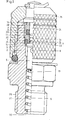
- Figur 1 eine Ventilkupplung im Maßstan 5 : 1, zur Hälfte im Axialschnitt im geschlossenen Zustand des Ventils;
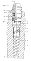
- Figur 2 eine Ventilkupplung in einem Manometerwahlschalter im geöffneten Zustand und
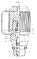
- Figur 3 eine weitere Ausführungsform einer Ventilkupplung im gleichen Maßstab und ebenfalls zur Hälfte im Axialschnitt im geschlossenen Zustand des Ventils.
- Wie aus den Figuren 1 und 2 ersichtlich ist, ist das Manometerwahlschalter-Gehäuse 2a bzw. die Kupplungsbuchse 2 mit einer Bohrung 29 versehen und nimmt die Ventilfeder 6, den darüber befindlichen Ventilkörper 5 und eine aus zwei Teilen bestehende Dichtbuchse 3.auf. Die Kupplungsbuchse 2 ist an ihrem unteren Ende mit einem Außengewinde 26 versehen, so daß diese in einfacher Weise mit dem Hydraulik- oder Pneumatiksystem verbunden werden kann. Bei einem Wahlschalter-Gehäuse 2a, entsprechend Figur 2 entfällt sinngemäß das Außengewinde 26.
- Der Ventilkörper 5 weist in dem in Figur 1 dargestellten Ausführungsbeispiel eine Axialbohrung 13 auf, die in radial gerichtete Bohrungen 8 übergeht.
- Die Ausführungsform nach Figur 2 weist statt dessen eine fertigungsgünstige Spiralnut 33 auf.
- Über den Radialbohrungen 8 bzw. der Spiralnut 33 ist der Ventilkörper 5 mit einer Dichtschulter 9 versehen, der sich eine Dichtung in Form einer Drosselstrecke 16 und ein kegelförmiges Endstück 31 anschließen.
- Im unteren Teil ihrer Bohrung 29 ist die Kupplungsbuchse 2 mit einem Schulterstück 30 versehen, gegen das sich die Ventilfeder 6 abstützt. Das obere Ende der Kupplungsbuchse 2 weist dagegen einen nach der Montage gefertigten Bördelring 15 auf, der die Dichtbuchse 3 sichert. Durch diese konstruktiven Maßnahmen ist es in vorteilhafter Weise möglich, die Montage des gesamten Systems von einer Seite durchzuführen, wobei nacheinander die Feder 6, der Ventilkörper 5 und die Dichtbuchse 3 eingeführt werden. Nach dieser Montage erfolgt die Herstellung des Bördelringes, so daß das gesamte System in einfacher Weise fixiert ist. Um den einfachen Einbau der erforderlichen 0-Ringe zu gewährleisten, ist die Dichtbuchse 3 mehrteilig ausgebildet, wobei das untere Teil 20 einen Ringsteg 21 aufweist, dessen radiale Außenseite mit der Innenwandung des Wahlschalter-Gehäuses 2a bzw. der Kupplungsbuchse 2 eine Dichtringkammer zur Aufnahme des Dichtringes 1 darstellt. Die radiale Innenseite des Ringsteges 21 bildet mit dem Ventilkörper 5 oberhalb seiner Dichtschulter 9 eine weitere Dichtung in Form einer zylindrischen Drosselstrecke 16 mit einem Drosselspalt einer definierten Länge und Breite.
- Der Ringsteg 21 dient gleichzeitig als Anschlag für die Dichtschulter 9 des Ventilkörpers 5 im geschlossenen Zustand des Ventils. In diesem geschlossenen Zustand preßt die Dichtschulter 9 mit ihrer Stirnfläche bzw. Außenkante gegen den Dichtring 1, der sich in der Dichtringkammer 14 befindet. Die axiale Außenfläche der Dichtschulter 9 ist derartig dimensioniert, daß sie mit der erweiterten Bohrung der Kupplungsbuchse 2 einen Ringspalt bildet, der in einen Ringkanal 11 übergeht. Dieser Ringkanal 11 ist über die radialen Bohrungen 8 und der Axialbohrung 13 bzw. der Spiralnut mit der Bohrung 18 der Kupplungsbuchse 2 strömungsmäßig verbunden.
- Die zylindrische Drosselstrecke 16 des Ventilkörpers 5 kann in einer besonderen Ausführungsform der Erfindung eine Ringnut zur Aufnahme eines Dichtringes 17 aus plastischem Material, aus einem mineralfaserverstärkten Polytetrafluoräthylen oder zur Aufnahme eines Kolbenringes aus Grauguß aufweisen. Diese Dichtringe sind kavitationsfest und verschleißarm.
- Das obere Teil 4 der Dichtbuchse 3 bildet mit dem unteren Teil 20 eine Ringnut 23 zur Aufnahme eines 0-Ringes, gegen den im geschlossenen Zustand des Ventils nach Figur 1 ein Nippel 24 einer Überwurfschutzkappe 25 anliegt.
- Wie aus der Figur 1 hervorgeht, preßt die obere Stirnfläche bzw. die Außenkante der Dichtschulter 9 im geschlossenen Ventilzustand gegen den aus einem elastomeren Werkstoff bestehenden Dichtring 1. Stromabwärts zum Dichtring 1 bildet der Ventilkörper 5 mit dem Ringsteg 21 der Dichtbuchse 3 eine in Form einer Drosselstrecke ausgebildete Dichtung 16.
- Wird der Ventilkörper 5 mit Hilfe des Hohlzapfens 32 aufgestoßen, so hebt der Dichtring 1 von der Schulter 9 des Ventilkörpers 5 ab, während die als Drosselstrecke ausgebildete Dichtung 16 ihre Dichtfunktion weiterhin aufrechterhält, bis der Ringsteg 21 den kegelförmigen Teil 31 des Ventilkörpers 5 verläßt.
- Wie insbesondere aus der Figur 2 deutlich hervorgeht, erstreckt sich die Abnahme der Dichtfunktion der bei diesem Ausführungsbeispiel stromaufwärts angeordneten Dichtung 16 zum Dichtring 1 während des Aufstoßvorganges des Ventilkörpers 5 mit Hilfe des Hohlzapfens 32 im Vergleich zur Abnahme der Dichtfunktion des Dichtringes 1 über einen längeren Hubweg, welcher u.a. durch die Höhe des Ringsteges 21 definiert ist. In der als Drosselstrecke ausgebildeten Dichtung 16 kann für besondere Anforderungen eine Ringnut 22 vorgesehen sein, in der sich ein Dichtring 17 befindet, der kavitations- und verschleißfest ausgebildet ist. Dieser Ring dient zur Überbrückung der Fertigungstoleranzen der metallischen Teile.
- Die Vermeidung einer Strömung oder Reduzierung der Geschwindigkeit des an der Dichtung 1 vorbeiströmenden Mediums bewirkt, daß eine Auswaschung oder Kavitation dieser Dichtung verhindert wird. Damit wird erreicht, daß das gesamte Dichtungssystem bei äußerst hohen Drücken und auch für Gase anwendbar ist, wobei durch die Zuordnung und Ausbildung der verschiedenen Dichtungen eine äußerst lange Lebensdauer sichergestellt wird.
- Aus der Figur 3 geht eine weitere Ausführungsform der Erfindung hervor, bei der ebenfalls, wie bei der Ausführungsform nach Figur 1, ein zylindrischer Ventilkörper 5 vorhanden ist, der mit der Stirnfläche und/ oder Außenkante seiner Dichtschulter 9 im geschlossenen Ventilzustand gegen einen aus elastomeren Werkstoff bestehenden Dichtring 1 preßt. Der Ventilkörper 5 bildet mit der Kupplungsbuchse 2 einen abdichtbaren Strömungskanal 11, wobei stromaufwärts zum Dichtring 1 eine weitere Dichtung 18 angeordnet ist, welche beim Aufstoßen des Ventilkörpers 5 ihre Dichtfunktion erst nach dem Abheben des Dichtringes 1 von der Dichtschulter 9 verzögert beendet. Damit stellt die Ausführungsform nach der Figur 3 bezüglich der Zuordnung der Dichtung 18 zur Dichtung 1 die sich ergebende Umkehrung dar, welche im übrigen die gleiche Wirkungsweise aufzeigt, wie die Ausführungsform nach den Figuren 1 und 2.
- In einer nicht näher dargestellten Ausführungsform können auch die nach den Figuren 1 bzw. 2 und 3 dargestellten Ausführungsformen miteinander kombiniert werden,derart, daß sowohl stromabwärts als auch stromaufwärts zum Dichtring 1 weitere Dichtungen angeordnet sind, die ihrerseit als Dichtkombinationen ausgebildet sein können, beispielsweise einer Drosselstrecke oder Labyrinthdichtung in Kombination mit Dichtringen. In allen Ausführungsformen ist der Dichtring 1 aus einem Elastomer hergestellt, während die bei den Dichtungen 16, 17 und 18 verwendeten Dichtringe aus einem kavitationsfesten Material bestehen.
Claims (10)
Priority Applications (5)
| Application Number | Priority Date | Filing Date | Title |
|---|---|---|---|
| DE8282104164T DE3274897D1 (en) | 1982-05-13 | 1982-05-13 | Valve fitting for a fluidic system |
| AT82104164T ATE24594T1 (de) | 1982-05-13 | 1982-05-13 | Ventilkupplung fuer fluidische systeme. |
| EP82104164A EP0094439B1 (de) | 1982-05-13 | 1982-05-13 | Ventilkupplung für fluidische Systeme |
| JP57183020A JPS58200889A (ja) | 1982-05-13 | 1982-10-20 | 流体システムでの、測定装置等を接続するための逆止弁を内蔵した弁座装置 |
| US06/887,971 US4703914A (en) | 1982-05-13 | 1986-07-21 | Valve joint for fluid systems |
Applications Claiming Priority (1)
| Application Number | Priority Date | Filing Date | Title |
|---|---|---|---|
| EP82104164A EP0094439B1 (de) | 1982-05-13 | 1982-05-13 | Ventilkupplung für fluidische Systeme |
Publications (2)
| Publication Number | Publication Date |
|---|---|
| EP0094439A1 true EP0094439A1 (de) | 1983-11-23 |
| EP0094439B1 EP0094439B1 (de) | 1986-12-30 |
Family
ID=8189031
Family Applications (1)
| Application Number | Title | Priority Date | Filing Date |
|---|---|---|---|
| EP82104164A Expired EP0094439B1 (de) | 1982-05-13 | 1982-05-13 | Ventilkupplung für fluidische Systeme |
Country Status (5)
| Country | Link |
|---|---|
| US (1) | US4703914A (de) |
| EP (1) | EP0094439B1 (de) |
| JP (1) | JPS58200889A (de) |
| AT (1) | ATE24594T1 (de) |
| DE (1) | DE3274897D1 (de) |
Cited By (2)
| Publication number | Priority date | Publication date | Assignee | Title |
|---|---|---|---|---|
| FR2612600A1 (fr) * | 1987-03-16 | 1988-09-23 | Rabusseau Edith | Dispositif testeur pour circuits hydrauliques |
| CN109061241A (zh) * | 2018-08-20 | 2018-12-21 | 重庆永富电线电缆有限公司 | 高压测试装置 |
Families Citing this family (13)
| Publication number | Priority date | Publication date | Assignee | Title |
|---|---|---|---|---|
| US5454631A (en) * | 1993-10-12 | 1995-10-03 | General Motors Corporation | Poppet assembly for a traction control modulator |
| AU765789B2 (en) * | 1998-06-25 | 2003-10-02 | Schroeder Industries Llc | Improved check valve arrangement for a diagnostic test point |
| AUPP432898A0 (en) * | 1998-06-25 | 1998-07-16 | W.G. Goetz & Sons Limited | Improved check valve arrangement for a diagnostic test point |
| EP1243839A3 (de) * | 2001-03-22 | 2003-01-29 | ALTO Deutschland GmbH | Hochdruck-Schnellkupplung |
| US6601609B2 (en) * | 2001-06-01 | 2003-08-05 | Shane S. Taylor | Fluid flow control valve |
| US20020179153A1 (en) * | 2001-06-01 | 2002-12-05 | Taylor Shane S. | Fluid flow control valve |
| US6659426B2 (en) * | 2001-12-26 | 2003-12-09 | Visteon Global Technologies, Inc. | Charge valve in a high pressure air conditioning system |
| DE102005026513A1 (de) * | 2005-06-09 | 2006-12-14 | Robert Bosch Gmbh | Ventil zur Steuerung eines Einspritzventils einer Brennkraftmaschine |
| US9200717B2 (en) | 2008-01-21 | 2015-12-01 | Ausco, Inc. | Pressure relief valve with singular body |
| US20090183782A1 (en) * | 2008-01-21 | 2009-07-23 | Martin Francis J | Pressure relief valve with singular body |
| US8313123B1 (en) * | 2009-08-05 | 2012-11-20 | Hinkle Derek H | Device for capping and sealing refrigeration service valve fittings of quick disconnect type |
| DE102020102277B4 (de) * | 2020-01-30 | 2022-07-21 | Hydrotechnik Gesellschaft mit beschränkter Haftung | Fluidanschluss, umfassend eine Anschlussarmatur und eine Ventil- und/oder Messkupplung für fluidische Systeme zur Erfassung von Arbeitsdrücken von fluidischen Medien |
| US20250153833A1 (en) * | 2023-11-15 | 2025-05-15 | Seamule, LLC | Outboard motor quick connect system |
Citations (3)
| Publication number | Priority date | Publication date | Assignee | Title |
|---|---|---|---|---|
| US2268020A (en) * | 1941-02-01 | 1941-12-30 | Reuben O Dahlstrom | Coupling valve |
| FR1402040A (fr) * | 1964-04-23 | 1965-06-11 | Staubli Freres & Cie | Dispositif de raccord rapide pour canalisations |
| GB2069083A (en) * | 1980-02-11 | 1981-08-19 | Compair Ind Ltd | Pipe coupling |
Family Cites Families (8)
| Publication number | Priority date | Publication date | Assignee | Title |
|---|---|---|---|---|
| US2931385A (en) * | 1956-10-31 | 1960-04-05 | Willis C Carlisle | Anti-scoring check valve |
| US3104088A (en) * | 1960-09-27 | 1963-09-17 | Crawford Fitting Co | Quick connect coupling |
| JPS4528865Y1 (de) * | 1966-02-23 | 1970-11-06 | ||
| US3754568A (en) * | 1971-10-14 | 1973-08-28 | Nupro Co | Check valve |
| FR2255542B1 (de) * | 1973-12-21 | 1976-11-19 | Kagan Aristide | |
| DE2756084C3 (de) * | 1977-12-16 | 1980-06-26 | Hydrotechnik Gmbh, 6052 Muehlheim | Schraubsicherung |
| US4269389A (en) * | 1978-03-08 | 1981-05-26 | Ekman Engineering Ag | Coupling device |
| US4287914A (en) * | 1980-01-16 | 1981-09-08 | Aeroquip Corporation | Self sealing coupling with full flow relief valve |
-
1982
- 1982-05-13 AT AT82104164T patent/ATE24594T1/de not_active IP Right Cessation
- 1982-05-13 DE DE8282104164T patent/DE3274897D1/de not_active Expired
- 1982-05-13 EP EP82104164A patent/EP0094439B1/de not_active Expired
- 1982-10-20 JP JP57183020A patent/JPS58200889A/ja active Granted
-
1986
- 1986-07-21 US US06/887,971 patent/US4703914A/en not_active Expired - Lifetime
Patent Citations (3)
| Publication number | Priority date | Publication date | Assignee | Title |
|---|---|---|---|---|
| US2268020A (en) * | 1941-02-01 | 1941-12-30 | Reuben O Dahlstrom | Coupling valve |
| FR1402040A (fr) * | 1964-04-23 | 1965-06-11 | Staubli Freres & Cie | Dispositif de raccord rapide pour canalisations |
| GB2069083A (en) * | 1980-02-11 | 1981-08-19 | Compair Ind Ltd | Pipe coupling |
Cited By (3)
| Publication number | Priority date | Publication date | Assignee | Title |
|---|---|---|---|---|
| FR2612600A1 (fr) * | 1987-03-16 | 1988-09-23 | Rabusseau Edith | Dispositif testeur pour circuits hydrauliques |
| CN109061241A (zh) * | 2018-08-20 | 2018-12-21 | 重庆永富电线电缆有限公司 | 高压测试装置 |
| CN109061241B (zh) * | 2018-08-20 | 2020-08-28 | 重庆永富电线电缆有限公司 | 高压测试装置 |
Also Published As
| Publication number | Publication date |
|---|---|
| DE3274897D1 (en) | 1987-02-05 |
| US4703914A (en) | 1987-11-03 |
| JPH0226118B2 (de) | 1990-06-07 |
| JPS58200889A (ja) | 1983-11-22 |
| ATE24594T1 (de) | 1987-01-15 |
| EP0094439B1 (de) | 1986-12-30 |
Similar Documents
| Publication | Publication Date | Title |
|---|---|---|
| EP0094439B1 (de) | Ventilkupplung für fluidische Systeme | |
| EP0233302B1 (de) | Fluidisches System mit Messvorrichtung | |
| EP0733822B1 (de) | Mit Fluid gefüllte Zylinder-Kolbenstangen-Einheit, insbesondere Gasfeder | |
| DE102007048907B4 (de) | Zylinderbaugruppe | |
| EP0233301B1 (de) | Steckkupplung für mehrere Schlauchverbindungen | |
| DE3218115C2 (de) | Ventilkupplung für fluidische Systeme | |
| DE112019000578T5 (de) | Fluidleckage-erfassungsvorrichtung und hin und her bewegende fluiddruckvorrichtung | |
| DE3141512A1 (de) | Gleit- und/oder gegenring einer gleitringdichtung | |
| DE3106210C2 (de) | Bohrlochkopf | |
| DE2504616A1 (de) | Hydraulisches sicherheitsventil fuer foerderbohrungen | |
| DE3820379C2 (de) | ||
| CH621646A5 (de) | ||
| DE2623370A1 (de) | Pumpe mit hochdruckabdichtung der pumpenwelle | |
| DE3517137C2 (de) | ||
| EP1334344A1 (de) | Einrichtung zum prüfen auf dichtigkeit einer dichtanordnung von rohren oder schachtbauwerken | |
| DE3208516C2 (de) | ||
| DE3015873A1 (de) | Automatisches zeitsteuerventil zur wasserabgabesteuerung in bewaesserungsanlagen | |
| DE3435734A1 (de) | Einrichtung zur leckfeststellung | |
| DE19530979C2 (de) | Gelenkabdichtung für Exzenterschneckenpumpen | |
| DE8327013U1 (de) | Messkupplung | |
| DE3500907A1 (de) | Vorrichtung zum absperren und belueften einer rohrleitung | |
| AT513015A1 (de) | Vorrichtung zum Anschluss eines Rohres an einem Anschlussnippel | |
| DE3706216A1 (de) | Durch fluiddruck anbringbarer rohrverbinder | |
| DE20209697U1 (de) | Stützzylinder | |
| DE4037279C2 (de) | Kompensator |
Legal Events
| Date | Code | Title | Description |
|---|---|---|---|
| PUAI | Public reference made under article 153(3) epc to a published international application that has entered the european phase |
Free format text: ORIGINAL CODE: 0009012 |
|
| AK | Designated contracting states |
Designated state(s): AT BE CH DE FR GB IT LI LU NL SE |
|
| 17P | Request for examination filed |
Effective date: 19831207 |
|
| ITCL | It: translation for ep claims filed |
Representative=s name: UFFICIO TECNICO ING. A. MANNUCCI |
|
| ITF | It: translation for a ep patent filed | ||
| GRAA | (expected) grant |
Free format text: ORIGINAL CODE: 0009210 |
|
| AK | Designated contracting states |
Kind code of ref document: B1 Designated state(s): AT BE CH DE FR GB IT LI LU NL SE |
|
| REF | Corresponds to: |
Ref document number: 24594 Country of ref document: AT Date of ref document: 19870115 Kind code of ref document: T |
|
| REF | Corresponds to: |
Ref document number: 3274897 Country of ref document: DE Date of ref document: 19870205 |
|
| ET | Fr: translation filed | ||
| PG25 | Lapsed in a contracting state [announced via postgrant information from national office to epo] |
Ref country code: LU Free format text: LAPSE BECAUSE OF NON-PAYMENT OF DUE FEES Effective date: 19870531 |
|
| PLBE | No opposition filed within time limit |
Free format text: ORIGINAL CODE: 0009261 |
|
| STAA | Information on the status of an ep patent application or granted ep patent |
Free format text: STATUS: NO OPPOSITION FILED WITHIN TIME LIMIT |
|
| 26N | No opposition filed | ||
| PGFP | Annual fee paid to national office [announced via postgrant information from national office to epo] |
Ref country code: LU Payment date: 19900404 Year of fee payment: 9 |
|
| PGFP | Annual fee paid to national office [announced via postgrant information from national office to epo] |
Ref country code: AT Payment date: 19900420 Year of fee payment: 9 |
|
| PGFP | Annual fee paid to national office [announced via postgrant information from national office to epo] |
Ref country code: CH Payment date: 19900523 Year of fee payment: 9 |
|
| PG25 | Lapsed in a contracting state [announced via postgrant information from national office to epo] |
Ref country code: AT Effective date: 19910513 |
|
| PG25 | Lapsed in a contracting state [announced via postgrant information from national office to epo] |
Ref country code: LI Effective date: 19910531 Ref country code: CH Effective date: 19910531 |
|
| REG | Reference to a national code |
Ref country code: CH Ref legal event code: PL |
|
| ITTA | It: last paid annual fee | ||
| EAL | Se: european patent in force in sweden |
Ref document number: 82104164.7 |
|
| PGFP | Annual fee paid to national office [announced via postgrant information from national office to epo] |
Ref country code: BE Payment date: 19950331 Year of fee payment: 14 |
|
| PGFP | Annual fee paid to national office [announced via postgrant information from national office to epo] |
Ref country code: SE Payment date: 19950517 Year of fee payment: 14 |
|
| PG25 | Lapsed in a contracting state [announced via postgrant information from national office to epo] |
Ref country code: SE Effective date: 19960514 |
|
| PGFP | Annual fee paid to national office [announced via postgrant information from national office to epo] |
Ref country code: NL Payment date: 19960529 Year of fee payment: 15 |
|
| PG25 | Lapsed in a contracting state [announced via postgrant information from national office to epo] |
Ref country code: BE Effective date: 19960531 |
|
| BERE | Be: lapsed |
Owner name: HYDROTECHNIK G.M.B.H. Effective date: 19960531 |
|
| EUG | Se: european patent has lapsed |
Ref document number: 82104164.7 |
|
| PG25 | Lapsed in a contracting state [announced via postgrant information from national office to epo] |
Ref country code: NL Effective date: 19971201 |
|
| NLV4 | Nl: lapsed or anulled due to non-payment of the annual fee |
Effective date: 19971201 |
|
| PGFP | Annual fee paid to national office [announced via postgrant information from national office to epo] |
Ref country code: GB Payment date: 20010508 Year of fee payment: 20 |
|
| PGFP | Annual fee paid to national office [announced via postgrant information from national office to epo] |
Ref country code: DE Payment date: 20010512 Year of fee payment: 20 |
|
| PGFP | Annual fee paid to national office [announced via postgrant information from national office to epo] |
Ref country code: FR Payment date: 20010523 Year of fee payment: 20 |
|
| REG | Reference to a national code |
Ref country code: GB Ref legal event code: IF02 |
|
| PG25 | Lapsed in a contracting state [announced via postgrant information from national office to epo] |
Ref country code: GB Free format text: LAPSE BECAUSE OF EXPIRATION OF PROTECTION Effective date: 20020512 |
|
| REG | Reference to a national code |
Ref country code: GB Ref legal event code: PE20 Effective date: 20020512 |