EP0094439A1 - Raccord à soupape pour système fluidique - Google Patents
Raccord à soupape pour système fluidique Download PDFInfo
- Publication number
- EP0094439A1 EP0094439A1 EP82104164A EP82104164A EP0094439A1 EP 0094439 A1 EP0094439 A1 EP 0094439A1 EP 82104164 A EP82104164 A EP 82104164A EP 82104164 A EP82104164 A EP 82104164A EP 0094439 A1 EP0094439 A1 EP 0094439A1
- Authority
- EP
- European Patent Office
- Prior art keywords
- sealing
- valve
- coupling
- bush
- sealing ring
- Prior art date
- Legal status (The legal status is an assumption and is not a legal conclusion. Google has not performed a legal analysis and makes no representation as to the accuracy of the status listed.)
- Granted
Links
Images
Classifications
-
- F—MECHANICAL ENGINEERING; LIGHTING; HEATING; WEAPONS; BLASTING
- F16—ENGINEERING ELEMENTS AND UNITS; GENERAL MEASURES FOR PRODUCING AND MAINTAINING EFFECTIVE FUNCTIONING OF MACHINES OR INSTALLATIONS; THERMAL INSULATION IN GENERAL
- F16L—PIPES; JOINTS OR FITTINGS FOR PIPES; SUPPORTS FOR PIPES, CABLES OR PROTECTIVE TUBING; MEANS FOR THERMAL INSULATION IN GENERAL
- F16L37/00—Couplings of the quick-acting type
- F16L37/28—Couplings of the quick-acting type with fluid cut-off means
- F16L37/38—Couplings of the quick-acting type with fluid cut-off means with fluid cut-off means in only one of the two pipe-end fittings
- F16L37/40—Couplings of the quick-acting type with fluid cut-off means with fluid cut-off means in only one of the two pipe-end fittings with a lift valve being opened automatically when the coupling is applied
- F16L37/42—Couplings of the quick-acting type with fluid cut-off means with fluid cut-off means in only one of the two pipe-end fittings with a lift valve being opened automatically when the coupling is applied the valve having an axial bore communicating with lateral apertures
-
- F—MECHANICAL ENGINEERING; LIGHTING; HEATING; WEAPONS; BLASTING
- F16—ENGINEERING ELEMENTS AND UNITS; GENERAL MEASURES FOR PRODUCING AND MAINTAINING EFFECTIVE FUNCTIONING OF MACHINES OR INSTALLATIONS; THERMAL INSULATION IN GENERAL
- F16L—PIPES; JOINTS OR FITTINGS FOR PIPES; SUPPORTS FOR PIPES, CABLES OR PROTECTIVE TUBING; MEANS FOR THERMAL INSULATION IN GENERAL
- F16L37/00—Couplings of the quick-acting type
- F16L37/28—Couplings of the quick-acting type with fluid cut-off means
- F16L37/38—Couplings of the quick-acting type with fluid cut-off means with fluid cut-off means in only one of the two pipe-end fittings
- F16L37/40—Couplings of the quick-acting type with fluid cut-off means with fluid cut-off means in only one of the two pipe-end fittings with a lift valve being opened automatically when the coupling is applied
Definitions
- the invention relates to a valve coupling, in particular valve measuring coupling for fluidic systems with high working pressures, consisting of a coupling bushing under line pressure, in the bore of which a spring-loaded and mechanically actuated check valve is arranged.
- Valve couplings of this type are used, for example, for the production of test or measurement connections on pressure lines, the coupling socket with an external thread generally being permanently installed on the pressure line of a hydraulic or pneumatic system, for example.
- a sealing nipple designed as a hollow pin is screwed onto this coupling bush by means of a union nut, which is firmly connected to a hose.
- the couplings can be connected, for example under pressure, ie without shutting down the system, to the corresponding measuring devices via measuring hoses.
- permanently installed devices such as pressure gauges, pressure gauge selector switches and pressure switches are connected, the flexible measuring hoses such as electrical cables can be laid, so that there is no need for complex pipe laying.
- valve body is arranged as a non-return valve on a compression spring and has a flow channel at its upper contact end.
- the valve coupling is provided with a sealing and anti-rotation ring, the sealing function of which is only guaranteed if a corresponding hose or closure cap is screwed tightly onto the coupling bushing with its sealing nipple.
- the invention has for its object to remedy this and in particular to propose a valve coupling, preferably a valve measuring coupling, which is suitable for fluidic systems with high working pressures and media of various viscosities, measures being proposed which consist of an elastomeric seal to protect against cavitation and leaching and to eliminate the effect of large volumes in measuring lines or the like of the connected circuit on the elastomeric seal.
- the decrease in the sealing function of the seals arranged downstream and / or upstream of the sealing ring extends during the opening process of the valve body in comparison with the decrease in the sealing function of the sealing ring and takes a longer stroke.
- the seals arranged downstream and / or upstream of the sealing ring still perform their sealing function, while due to the shorter stroke of the sealing ring, this is removed from the disadvantageous effect of an otherwise occurring flow and a cavitation or leaching which is formed as a result.
- the seals which are present downstream and / or upstream of the sealing ring, are designed as throttle sections and / or labyrinth seals. This makes it possible to have the pressure equalization run in a defined and predetermined manner. Measurements have shown that the effect of the Reducing the speed of the medium flowing past the seals is usually sufficient to prevent washouts and cavitation on the sealing ring itself.
- the seals arranged downstream and / or upstream of the sealing ring each have a cavitation and wear-resistant sealing ring mounted in an annular groove.
- the cylindrical valve body has an axial bore which merges into radially directed bores, with the sealing shoulder being arranged above the radial bores, which is followed by the cylindrical throttle section with a conical end piece, the coupling bush for receiving the sealing shoulder of the valve body and the sealing bush has an enlarged bore.
- the coupling bushing is provided in the lower part of its bore with a shoulder piece against which the valve spring is supported, while the upper end of the coupling bushing has a flanged ring which, after assembly, secures the sealing bushing. This considerably simplifies assembly, since the entire elements can be inserted from one side and the valve and sealing system can then be anchored by producing the crimp ring.
- the sealing bush is formed in several parts, the lower part having an annular web, the radial outside of which forms a sealing ring chamber with the inner wall of the coupling bush for receiving the sealing ring, the radial inside of which represents the outer boundary of the seal.
- the ring web is advantageously designed as a stop for the sealing shoulder of the valve body.
- the sealing shoulder presses with its outer edge and / or end face in the closed valve state against the sealing ring, and the axial outer surface of the sealing shoulder forms an annular channel with the enlarged bore of the coupling bush.
- the upper part of the sealing bush forms with the lower part of the sealing bush an annular groove for receiving an O-ring, against which a nipple of a union protection cap rests when the valve is closed.
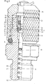
- the manometer selector switch housing 2a or the coupling bush 2 is provided with a bore 29 and accommodates the valve spring 6, the valve body 5 above it and a sealing bush 3 consisting of two parts.
- the coupling sleeve 2 is provided at its lower end with an external thread 26 so that it is connected in a simple manner to the hydraulic or pneumatic system can be. In the case of a selector switch housing 2a, corresponding to FIG. 2, the external thread 26 does not apply.
- valve body 5 has an axial bore 13 which merges into radially directed bores 8.
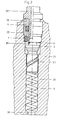
- the embodiment according to FIG. 2 instead has a spiral groove 33 which is favorable to manufacture.
- valve body 5 Above the radial bores 8 or the spiral groove 33, the valve body 5 is provided with a sealing shoulder 9, which is followed by a seal in the form of a throttle section 16 and a conical end piece 31.
- the coupling bush 2 In the lower part of its bore 29, the coupling bush 2 is provided with a shoulder piece 30 against which the valve spring 6 is supported.
- the upper end of the coupling bush 2, on the other hand, has a crimp ring 15 which is produced after assembly and which secures the sealing bush 3.
- the sealing bush 3 is of multi-part design, the lower part 20 having an annular web 21, the radial outside of which, with the inner wall of the selector switch housing 2a or the coupling bush 2, has a sealing ring chamber for receiving the Represents sealing ring 1.
- the radial inside of the ring web 21 forms with the Valve body 5 above its sealing shoulder 9 a further seal in the form of a cylindrical throttle section 16 with a throttle gap of a defined length and width.
- the ring web 21 also serves as a stop for the sealing shoulder 9 of the valve body 5 in the closed state of the valve.
- the sealing shoulder 9 presses with its end face or outer edge against the sealing ring 1, which is located in the sealing ring chamber 14.
- the axial outer surface of the sealing shoulder 9 is dimensioned such that it forms an annular gap with the enlarged bore of the coupling bush 2, which merges into an annular channel 11.
- This ring channel 11 is connected via the radial bores 8 and the axial bore 13 or the spiral groove with the bore 18 of the coupling bush 2 in terms of flow.
- the cylindrical throttle section 16 of the valve body 5 can have an annular groove for receiving a sealing ring 17 made of plastic material, made of a mineral fiber reinforced polytetrafluoroethylene or for receiving a piston ring made of gray cast iron.
- sealing rings are cavitation-proof and wear-resistant.
- the upper part 4 of the sealing bush 3 forms with the lower part 20 an annular groove 23 for receiving an O-ring, against which a nipple 24 of a cap 25 rests when the valve according to FIG. 1 is closed.
- the upper end face or the outer edge of the sealing shoulder 9 presses in ge closed valve state against the sealing ring made of an elastomeric material 1.
- the valve body 5 Downstream of the sealing ring 1, the valve body 5 forms with the annular web 21 of the sealing bush 3 a seal 16 in the form of a throttle section.
- valve body 5 If the valve body 5 is pushed open with the aid of the hollow pin 32, the sealing ring 1 lifts off the shoulder 9 of the valve body 5, while the seal 16 designed as a throttle section continues to maintain its sealing function until the annular web 21 leaves the conical part 31 of the valve body 5.
- an annular groove 22 can be provided for special requirements, in which there is a sealing ring 17 which is designed to be cavitation-resistant and wear-resistant. This ring is used to bridge the manufacturing tolerances of the metallic parts.
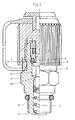
- FIG. 3 shows a further embodiment of the invention, in which, as in the embodiment according to FIG. 1, there is also a cylindrical valve body 5, which with the end face and / or outer edge of its sealing shoulder 9 in the closed valve state against an elastomeric material existing sealing ring 1 presses.
- the valve body 5 forms with the coupling bush 2 a sealable flow channel 11, a further seal 18 being arranged upstream of the sealing ring 1, which ends its sealing function when the valve body 5 is pushed open after the sealing ring 1 has been lifted off the sealing shoulder 9.
- the embodiment according to FIG. 3 thus represents the resulting reversal with regard to the assignment of the seal 18 to the seal 1, which otherwise shows the same mode of action as the embodiment according to FIGS. 1 and 2.
- the embodiments shown in FIGS. 1 or 2 and 3 can also be combined with one another such that further seals are arranged both downstream and upstream of the sealing ring 1, which in turn can be designed as sealing combinations, for example one Throttle section or labyrinth seal in combination with sealing rings.
- the sealing ring 1 is made of an elastomer, while the sealing rings used in the seals 16, 17 and 18 consist of a cavitation-resistant material.
Priority Applications (5)
| Application Number | Priority Date | Filing Date | Title |
|---|---|---|---|
| EP82104164A EP0094439B1 (fr) | 1982-05-13 | 1982-05-13 | Raccord à soupape pour système fluidique |
| DE8282104164T DE3274897D1 (en) | 1982-05-13 | 1982-05-13 | Valve fitting for a fluidic system |
| AT82104164T ATE24594T1 (de) | 1982-05-13 | 1982-05-13 | Ventilkupplung fuer fluidische systeme. |
| JP57183020A JPS58200889A (ja) | 1982-05-13 | 1982-10-20 | 流体システムでの、測定装置等を接続するための逆止弁を内蔵した弁座装置 |
| US06/887,971 US4703914A (en) | 1982-05-13 | 1986-07-21 | Valve joint for fluid systems |
Applications Claiming Priority (1)
| Application Number | Priority Date | Filing Date | Title |
|---|---|---|---|
| EP82104164A EP0094439B1 (fr) | 1982-05-13 | 1982-05-13 | Raccord à soupape pour système fluidique |
Publications (2)
| Publication Number | Publication Date |
|---|---|
| EP0094439A1 true EP0094439A1 (fr) | 1983-11-23 |
| EP0094439B1 EP0094439B1 (fr) | 1986-12-30 |
Family
ID=8189031
Family Applications (1)
| Application Number | Title | Priority Date | Filing Date |
|---|---|---|---|
| EP82104164A Expired EP0094439B1 (fr) | 1982-05-13 | 1982-05-13 | Raccord à soupape pour système fluidique |
Country Status (5)
| Country | Link |
|---|---|
| US (1) | US4703914A (fr) |
| EP (1) | EP0094439B1 (fr) |
| JP (1) | JPS58200889A (fr) |
| AT (1) | ATE24594T1 (fr) |
| DE (1) | DE3274897D1 (fr) |
Cited By (2)
| Publication number | Priority date | Publication date | Assignee | Title |
|---|---|---|---|---|
| FR2612600A1 (fr) * | 1987-03-16 | 1988-09-23 | Rabusseau Edith | Dispositif testeur pour circuits hydrauliques |
| CN109061241A (zh) * | 2018-08-20 | 2018-12-21 | 重庆永富电线电缆有限公司 | 高压测试装置 |
Families Citing this family (11)
| Publication number | Priority date | Publication date | Assignee | Title |
|---|---|---|---|---|
| US5454631A (en) * | 1993-10-12 | 1995-10-03 | General Motors Corporation | Poppet assembly for a traction control modulator |
| AUPP432898A0 (en) * | 1998-06-25 | 1998-07-16 | W.G. Goetz & Sons Limited | Improved check valve arrangement for a diagnostic test point |
| AU765789B2 (en) * | 1998-06-25 | 2003-10-02 | Schroeder Industries Llc | Improved check valve arrangement for a diagnostic test point |
| EP1243839A3 (fr) * | 2001-03-22 | 2003-01-29 | ALTO Deutschland GmbH | Raccord rapide haute pression |
| US6601609B2 (en) | 2001-06-01 | 2003-08-05 | Shane S. Taylor | Fluid flow control valve |
| US20020179153A1 (en) * | 2001-06-01 | 2002-12-05 | Taylor Shane S. | Fluid flow control valve |
| US6659426B2 (en) * | 2001-12-26 | 2003-12-09 | Visteon Global Technologies, Inc. | Charge valve in a high pressure air conditioning system |
| DE102005026513A1 (de) * | 2005-06-09 | 2006-12-14 | Robert Bosch Gmbh | Ventil zur Steuerung eines Einspritzventils einer Brennkraftmaschine |
| US20090183782A1 (en) * | 2008-01-21 | 2009-07-23 | Martin Francis J | Pressure relief valve with singular body |
| US9200717B2 (en) | 2008-01-21 | 2015-12-01 | Ausco, Inc. | Pressure relief valve with singular body |
| US8313123B1 (en) * | 2009-08-05 | 2012-11-20 | Hinkle Derek H | Device for capping and sealing refrigeration service valve fittings of quick disconnect type |
Citations (3)
| Publication number | Priority date | Publication date | Assignee | Title |
|---|---|---|---|---|
| US2268020A (en) * | 1941-02-01 | 1941-12-30 | Reuben O Dahlstrom | Coupling valve |
| FR1402040A (fr) * | 1964-04-23 | 1965-06-11 | Staubli Freres & Cie | Dispositif de raccord rapide pour canalisations |
| GB2069083A (en) * | 1980-02-11 | 1981-08-19 | Compair Ind Ltd | Pipe coupling |
Family Cites Families (8)
| Publication number | Priority date | Publication date | Assignee | Title |
|---|---|---|---|---|
| US2931385A (en) * | 1956-10-31 | 1960-04-05 | Willis C Carlisle | Anti-scoring check valve |
| US3104088A (en) * | 1960-09-27 | 1963-09-17 | Crawford Fitting Co | Quick connect coupling |
| JPS4528865Y1 (fr) * | 1966-02-23 | 1970-11-06 | ||
| US3754568A (en) * | 1971-10-14 | 1973-08-28 | Nupro Co | Check valve |
| FR2255542B1 (fr) * | 1973-12-21 | 1976-11-19 | Kagan Aristide | |
| DE2756084C3 (de) * | 1977-12-16 | 1980-06-26 | Hydrotechnik Gmbh, 6052 Muehlheim | Schraubsicherung |
| US4269389A (en) * | 1978-03-08 | 1981-05-26 | Ekman Engineering Ag | Coupling device |
| US4287914A (en) * | 1980-01-16 | 1981-09-08 | Aeroquip Corporation | Self sealing coupling with full flow relief valve |
-
1982
- 1982-05-13 AT AT82104164T patent/ATE24594T1/de not_active IP Right Cessation
- 1982-05-13 DE DE8282104164T patent/DE3274897D1/de not_active Expired
- 1982-05-13 EP EP82104164A patent/EP0094439B1/fr not_active Expired
- 1982-10-20 JP JP57183020A patent/JPS58200889A/ja active Granted
-
1986
- 1986-07-21 US US06/887,971 patent/US4703914A/en not_active Expired - Lifetime
Patent Citations (3)
| Publication number | Priority date | Publication date | Assignee | Title |
|---|---|---|---|---|
| US2268020A (en) * | 1941-02-01 | 1941-12-30 | Reuben O Dahlstrom | Coupling valve |
| FR1402040A (fr) * | 1964-04-23 | 1965-06-11 | Staubli Freres & Cie | Dispositif de raccord rapide pour canalisations |
| GB2069083A (en) * | 1980-02-11 | 1981-08-19 | Compair Ind Ltd | Pipe coupling |
Cited By (3)
| Publication number | Priority date | Publication date | Assignee | Title |
|---|---|---|---|---|
| FR2612600A1 (fr) * | 1987-03-16 | 1988-09-23 | Rabusseau Edith | Dispositif testeur pour circuits hydrauliques |
| CN109061241A (zh) * | 2018-08-20 | 2018-12-21 | 重庆永富电线电缆有限公司 | 高压测试装置 |
| CN109061241B (zh) * | 2018-08-20 | 2020-08-28 | 重庆永富电线电缆有限公司 | 高压测试装置 |
Also Published As
| Publication number | Publication date |
|---|---|
| JPH0226118B2 (fr) | 1990-06-07 |
| ATE24594T1 (de) | 1987-01-15 |
| US4703914A (en) | 1987-11-03 |
| JPS58200889A (ja) | 1983-11-22 |
| DE3274897D1 (en) | 1987-02-05 |
| EP0094439B1 (fr) | 1986-12-30 |
Similar Documents
| Publication | Publication Date | Title |
|---|---|---|
| DE3122626C2 (fr) | ||
| EP0094439B1 (fr) | Raccord à soupape pour système fluidique | |
| EP0233302B1 (fr) | Système fluidique avec dispositif de mesure | |
| EP0733822B1 (fr) | Unité de piston/cilindre rempli à fluide,un verin à gaz en particulier | |
| EP0233301B1 (fr) | Accouplement enfichable pour plusieurs raccords de tuyaux | |
| DE3218115C2 (de) | Ventilkupplung für fluidische Systeme | |
| DE3141512A1 (de) | Gleit- und/oder gegenring einer gleitringdichtung | |
| DE3106210C2 (de) | Bohrlochkopf | |
| DE2504616A1 (de) | Hydraulisches sicherheitsventil fuer foerderbohrungen | |
| DE3820379C2 (fr) | ||
| CH621646A5 (fr) | ||
| DE2623370A1 (de) | Pumpe mit hochdruckabdichtung der pumpenwelle | |
| DE3517137C2 (fr) | ||
| EP1334344A1 (fr) | Dispositif de controle de l'etancheite d'un systeme d'etancheite de tuyaux ou de constructions a puits | |
| DE4224419A1 (de) | Vorrichtung zur Abdichtung von Rohren | |
| DE3208516C2 (fr) | ||
| DE3015873A1 (de) | Automatisches zeitsteuerventil zur wasserabgabesteuerung in bewaesserungsanlagen | |
| DE19530979C2 (de) | Gelenkabdichtung für Exzenterschneckenpumpen | |
| DE8327013U1 (de) | Messkupplung | |
| DE3435734A1 (de) | Einrichtung zur leckfeststellung | |
| DE112019000578T5 (de) | Fluidleckage-erfassungsvorrichtung und hin und her bewegende fluiddruckvorrichtung | |
| DE3033739A1 (de) | Druckuebersetzer zur hoechstdruckerzeugung | |
| AT513015A1 (de) | Vorrichtung zum Anschluss eines Rohres an einem Anschlussnippel | |
| DE3500907A1 (de) | Vorrichtung zum absperren und belueften einer rohrleitung | |
| DE4037279C2 (de) | Kompensator |
Legal Events
| Date | Code | Title | Description |
|---|---|---|---|
| PUAI | Public reference made under article 153(3) epc to a published international application that has entered the european phase |
Free format text: ORIGINAL CODE: 0009012 |
|
| AK | Designated contracting states |
Designated state(s): AT BE CH DE FR GB IT LI LU NL SE |
|
| 17P | Request for examination filed |
Effective date: 19831207 |
|
| ITCL | It: translation for ep claims filed |
Representative=s name: UFFICIO TECNICO ING. A. MANNUCCI |
|
| ITF | It: translation for a ep patent filed |
Owner name: UFFICIO TECNICO ING. A. MANNUCCI |
|
| GRAA | (expected) grant |
Free format text: ORIGINAL CODE: 0009210 |
|
| AK | Designated contracting states |
Kind code of ref document: B1 Designated state(s): AT BE CH DE FR GB IT LI LU NL SE |
|
| REF | Corresponds to: |
Ref document number: 24594 Country of ref document: AT Date of ref document: 19870115 Kind code of ref document: T |
|
| REF | Corresponds to: |
Ref document number: 3274897 Country of ref document: DE Date of ref document: 19870205 |
|
| ET | Fr: translation filed | ||
| PG25 | Lapsed in a contracting state [announced via postgrant information from national office to epo] |
Ref country code: LU Free format text: LAPSE BECAUSE OF NON-PAYMENT OF DUE FEES Effective date: 19870531 |
|
| PLBE | No opposition filed within time limit |
Free format text: ORIGINAL CODE: 0009261 |
|
| STAA | Information on the status of an ep patent application or granted ep patent |
Free format text: STATUS: NO OPPOSITION FILED WITHIN TIME LIMIT |
|
| 26N | No opposition filed | ||
| PGFP | Annual fee paid to national office [announced via postgrant information from national office to epo] |
Ref country code: LU Payment date: 19900404 Year of fee payment: 9 |
|
| PGFP | Annual fee paid to national office [announced via postgrant information from national office to epo] |
Ref country code: AT Payment date: 19900420 Year of fee payment: 9 |
|
| PGFP | Annual fee paid to national office [announced via postgrant information from national office to epo] |
Ref country code: CH Payment date: 19900523 Year of fee payment: 9 |
|
| PG25 | Lapsed in a contracting state [announced via postgrant information from national office to epo] |
Ref country code: AT Effective date: 19910513 |
|
| PG25 | Lapsed in a contracting state [announced via postgrant information from national office to epo] |
Ref country code: LI Effective date: 19910531 Ref country code: CH Effective date: 19910531 |
|
| REG | Reference to a national code |
Ref country code: CH Ref legal event code: PL |
|
| ITTA | It: last paid annual fee | ||
| EAL | Se: european patent in force in sweden |
Ref document number: 82104164.7 |
|
| PGFP | Annual fee paid to national office [announced via postgrant information from national office to epo] |
Ref country code: BE Payment date: 19950331 Year of fee payment: 14 |
|
| PGFP | Annual fee paid to national office [announced via postgrant information from national office to epo] |
Ref country code: SE Payment date: 19950517 Year of fee payment: 14 |
|
| PG25 | Lapsed in a contracting state [announced via postgrant information from national office to epo] |
Ref country code: SE Effective date: 19960514 |
|
| PGFP | Annual fee paid to national office [announced via postgrant information from national office to epo] |
Ref country code: NL Payment date: 19960529 Year of fee payment: 15 |
|
| PG25 | Lapsed in a contracting state [announced via postgrant information from national office to epo] |
Ref country code: BE Effective date: 19960531 |
|
| BERE | Be: lapsed |
Owner name: HYDROTECHNIK G.M.B.H. Effective date: 19960531 |
|
| EUG | Se: european patent has lapsed |
Ref document number: 82104164.7 |
|
| PG25 | Lapsed in a contracting state [announced via postgrant information from national office to epo] |
Ref country code: NL Effective date: 19971201 |
|
| NLV4 | Nl: lapsed or anulled due to non-payment of the annual fee |
Effective date: 19971201 |
|
| PGFP | Annual fee paid to national office [announced via postgrant information from national office to epo] |
Ref country code: GB Payment date: 20010508 Year of fee payment: 20 |
|
| PGFP | Annual fee paid to national office [announced via postgrant information from national office to epo] |
Ref country code: DE Payment date: 20010512 Year of fee payment: 20 |
|
| PGFP | Annual fee paid to national office [announced via postgrant information from national office to epo] |
Ref country code: FR Payment date: 20010523 Year of fee payment: 20 |
|
| REG | Reference to a national code |
Ref country code: GB Ref legal event code: IF02 |
|
| PG25 | Lapsed in a contracting state [announced via postgrant information from national office to epo] |
Ref country code: GB Free format text: LAPSE BECAUSE OF EXPIRATION OF PROTECTION Effective date: 20020512 |
|
| REG | Reference to a national code |
Ref country code: GB Ref legal event code: PE20 Effective date: 20020512 |