EP0092984A2 - Dispositif pour enregistrer et reproduire de l'information numérique sur un milieu d'enregistrement - Google Patents
Dispositif pour enregistrer et reproduire de l'information numérique sur un milieu d'enregistrement Download PDFInfo
- Publication number
- EP0092984A2 EP0092984A2 EP83302283A EP83302283A EP0092984A2 EP 0092984 A2 EP0092984 A2 EP 0092984A2 EP 83302283 A EP83302283 A EP 83302283A EP 83302283 A EP83302283 A EP 83302283A EP 0092984 A2 EP0092984 A2 EP 0092984A2
- Authority
- EP
- European Patent Office
- Prior art keywords
- recording
- reproducing
- digital
- analog
- clock signals
- Prior art date
- Legal status (The legal status is an assumption and is not a legal conclusion. Google has not performed a legal analysis and makes no representation as to the accuracy of the status listed.)
- Withdrawn
Links
Images
Classifications
-
- H—ELECTRICITY
- H04—ELECTRIC COMMUNICATION TECHNIQUE
- H04N—PICTORIAL COMMUNICATION, e.g. TELEVISION
- H04N9/00—Details of colour television systems
- H04N9/79—Processing of colour television signals in connection with recording
- H04N9/80—Transformation of the television signal for recording, e.g. modulation, frequency changing; Inverse transformation for playback
- H04N9/804—Transformation of the television signal for recording, e.g. modulation, frequency changing; Inverse transformation for playback involving pulse code modulation of the colour picture signal components
-
- G—PHYSICS
- G11—INFORMATION STORAGE
- G11B—INFORMATION STORAGE BASED ON RELATIVE MOVEMENT BETWEEN RECORD CARRIER AND TRANSDUCER
- G11B20/00—Signal processing not specific to the method of recording or reproducing; Circuits therefor
- G11B20/10—Digital recording or reproducing
Definitions
- This invention relates generally to information signal recording and reproducing apparatus and, more particularly, is directed to a video tape recorder which provides different amounts of recording and reproducing time on a magnetic tape.
- VTR Video tape recorders
- the sampling frequencies of the luminance component, red color difference signal component and blue color difference signal component can be selected as 4f0, 2f 0 and 2f 0 , where 4f 0 is a predetermined frequency, for example, 13.5 MHz.
- the relationship between the sampling frequencies of the luminance component, red color difference signal component and blue color difference signal component is 4:2:2.
- the sampling frequency of the color video signal is 8f 0 .
- the sampling frequencies of the luminance component and red and blue color difference signal components may be selected as 2f o , f O and f 0 , respectively, that is, the relationship between the sampling frequencies is selected as 2:1:1.
- the sampling frequency of the color video signal is 4f 0*
- the circuitry necessary for the 2:1:1 system need be less complicated than that for the 4:2:2 system, thereby reducing the cost of the apparatus.
- the speed of rotation of the rotary magnetic heads of the VTR, the speed of movement of the magnetic tape past the heads and the operating frequency of the processing circuitry generally varies with the hierarchy system utilized, that is, the 4:2:2 system, the 2:1:1 system and other systems.
- apparatus for recording and reproducing an information signal on a record medium comprises drive means for moving the record medium; a recording section including recording converting means for converting the information signal into digital form such that the digitized information signal has a recording sampling frequency associated therewith, recording processing means for processing the digitized information signal at a recording operating frequency, and movable recording transducer means for recording the processed digitized information signal on the record medium as the latter is moved at a recording speed by the drive means; a reproducing section including reproducing transducer means for reproducing the processed digitized information signal from the record medium as the latter is moved at a reproducing speed by the drive means, movable reproducing processing means for processing the reproduced processed digitized information signal at a reproducing operating frequency to produce a digitized information signal having a reproducing sampling frequency associated therewith, and reproducing converting means for converting the digitized information signal from the reproducing processing means into analog form; and control means for controlling changes in the speed of movement of the recording transducer means
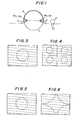
- a rotary magnetic head assembly that can be used with the present invention includes a guide drum 2 about which a magnetic tape 4 is partially wrapped, tape 4 being guided around guide drum 2 by guide pins or rollers 6 and 8.
- Guide drum 2 may include a lower stationary drum and an upper rotary drum to which magnetic recording heads H R1 and H R2 are secured for rotation therewith so as to record information signals, such as video and/or audio signals on record tracks extending obliquely on magnetic tape 4 as the latter is advanced longitudinally thereof.
- Magnetic recording heads H R1 and H R2 are positioned diametrically opposite to each other, that is, 180° apart so as to trace alternate tracks on magnetic tape 4.
- two reproducing magnetic heads H P1 and H P2 are also provided at positions corresponding to recording magnetic heads H R1 and H R2' respectively, on the upper rotary drum for tracing the same respective record tracks to reproduce the information signals recorded thereon.
- Magnetic tape 4 is advanced in its longitudinal direction around guide drum 2 by a capstan assembly comprised of a pinch roller 12, and a capstan 10 which is driven by a capstan motor (not shown) which, in turn, is controlled by a control circuit 11 (Fig. 2), the latter circuit also controlling the speed of rotation of the upper rotary drum and thereby the recording magnetic heads H R1 , H R2 and reproducing magnetic heads H P1 , H P2 .
- magnetic heads H Rl and H R2 rotate with the upper rotary drum of guide drum 2 so as to record the information signals in the record tracks extending obliquely on magnetic tape 4. It is to be noted that, although only two magnetic heads have been shown for recording and reproducing, any suitable number of magnetic heads may be used, for example, four magnetic heads or the like.
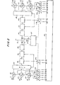
- the luminance component Y of the color video signal is supplied from an input terminal 20 to an analog-to-digital (A/D) converter 22 where it is sampled with a sampling frequency A 1 f 0 and converted into digital form.
- the red color difference signal (R - Y) component is supplied through an input terminal 24 to an analog-to-digital (A/D) converter 26 which samples the red color difference signal component with a sampling frequency A 2 f 0 .
- the blue color difference signal (B - Y) component is supplied through an input terminal 28 to another analog-to-digital (A/D) converter 30 which samples the blue color difference signal component with a sampling frequency A 3 f 0 .
- A/D analog-to-digital
- the luminance component Y generally contains more important information with respect to the picture information to be recorded than the red and blue color difference signal components, and accordingly, the luminance component Y is generally sampled with a sampling frequency which is equal to or greater than the sampling frequencies of the red and blue color difference signal components.
- the digitized signals from A/D converters 22, 26 and 30 are supplied to a multiplexer 32 to produce a multiplexed digital video signal which is divided into data blocks, with each data block having a block synchronizing signal added thereto.
- the multiplexed digital color video signal has a sampling frequency associated therewith which corresponds to the sum of sampling frequencies of each of the individual components thereof.
- the multiplexed digital color video signal is supplied to an error correction encoder 34 which encodes each predetermined number of data blocks with error correcting codes and then supplies the multiplexed digital color video signal to a channel encoder 36 which distributes the encoded signal to two or more channels, that is, for each predetermined number of data blocks and error correcting codes appended thereto.
- channel encoder 36 divides or separates the digital color video signal into two channels.
- the digital color video signal may be divided into more than two channels.
- the digital color video signal in each channel from channel encoder 36 is supplied through a recording processor 38 to one recording magnetic head H R .
- a recording processor 38 and recording magnetic head H R are shown in Fig. 2 to provide a simplified drawing for better explanation purposes, but that other recording processors 38 and magnetic heads H R are provided for the other channel or channels. Accordingly, the digital color video signal is recorded by magnetic heads H R in record tracks extending obliquely on magnetic tape 4.
- each reproducing rotary magnetic head H reproduces one channel of the digital color video signal which is then processed in a reproducing processor 40 and supplied to a channel decoder 42 which combines the plurality of channels to produce a single channel digital color video signal which is supplied to an error correction decoder 44.
- the latter circuit corrects any errors detected in the digital color video signal by means of error correcting codes added thereto by error correction encoder 34. If such errors are not correctable, error correction decoder 44 performs an error concealing operation.
- the error corrected digital color video signal from error correction decoder 44 is supplied to a demultiplexer 46 which separates the digital color video signal into the luminance component Y, the red color difference signal (R - Y) component and the blue color difference signal (B - Y) component. Then, the digitized luminance component Y is supplied to a digital-to-analog (D/A) converter 48 which converts the digitized luminance component Y into analog form and supplies the same to an output terminal 48. In like manner, the red color difference signal (R - Y) component is supplied to a digital-to-analog (D/A) converter 50 which converts the digitized signal into analog form and supplies the same to an output terminal 52.
- D/A digital-to-analog
- the blue color difference signal (B - Y) component is supplied to a digital-to-analog (D/A) converter 54 which converts the digitized signal into analog form and supplies the same to an output terminal 56.
- D/A digital-to-analog
- a clock signal generator 58 is provided which generates clock signals with frequencies 8f 0 , 4f 0 , 2f o and f 0 in response to a reference clock signal.
- the frequency 4f O is selected as 13.5 MHz which is 854 times the horizontal frequency of an NTSC television signal and is 864 times the horizontal frequency of PAL and SECAM television signals.
- the sampling frequencies of the luminance component Y, the red color difference signal (R - Y) component and the blue color difference signal (B - Y) component are respectively selected as 4f 0 , 2f 0 and 2f 0
- the respective sampling frequencies are selected as 2f 0 , f 0 and f 0 .
- switches SW 1' SW 2 and SW 3 are connected between clock signal generator 58 and A/D converters 22, 26 and 30, respectively, for supplying clock signals to the latter circuits having recording sampling frequencies A l f O , A 2 f 0 and A 3 f 0 , respectively.
- switches SW 1 , SW 2 and SW 3 supply clock signals having frequencies 4f 0 , 2f 0 and 2f 0 , respectively, to A/D converting circuits 22, 26 and 30, respectively.
- switches SW 1 , SW 2 and SW 3 supply clock signals having frequencies 2f 0 , f 0 and f to A/D converting circuits 22, 26 and 30, respectively.
- each switch circuit includes a movable arm a and fixed terminals b and c supplied with clock signals for the 4:2:2 system and 2:1:1 system, respectively.
- terminal b of the switches are supplied with clock signals having frequencies 4f 0 , 2f o and 2f 0 , respectively, for the 4:2:2 system
- terminal c of the switches are supplied with clock signals having frequencies 2f 0 , f 0 and f 0 , respectively, for the 2:1:1 system.
- the operating frequency of encoders 34 and 36 must correspond to the. sampling frequency thereof.
- the operating frequency is 8f 0
- the operating frequency is 4f 0 .
- another switch SW 4 is provided having a movable arm a, a fixed terminal b supplied with a clock signal from clock signal generator 58 having a frequency 8f 0 , and a fixed terminal c supplied with a clock signal from clock signal generator 58 having a frequency 4f 0 .
- the output clock signal from switch SW 4 is supplied to multiplexer 32, error correction encoder 34 and channel encoder 36 for controlling the latter circuits at the operating frequency corresponding to the hierarchy system being utilized.
- all of switches SW 1 - SW 4 are ganged together, as shown by the dashed line in Fig. 2, such that the movable arms a of all of the switches contact terminals b thereof when operating in the 4:2:2 system and contact terminals c thereof when operating in the 2:1:1 system.
- switches SW 5' SW 6 and SW 7 are provided for supplying clock signals having frequencies corresponding to the sampling frequency of the color video signal supplied to demultiplexer 46, to D/A converters 46, 50 and 54, respectively. More particularly, switches SW 5 - SW 7 each include a movable arm a which is movable between two fixed terminals b and c for use in the 4:2:2 system and 2:1:1 system, respectively.
- clock signals having frequencies 4f 0 , 2f o and 2f 0 are supplied to D/A converters 46, 50 and 54, while clock signals having frequencies 2f 0 , f 0 and f 0 are supplied through switches SW 5 - SW 7 to D/A converters 46, 50 and 54, respectively, when the movable arms a thereof are in contact with terminals c thereof.
- clock signals having frequencies 4f 0 , 2f o and 2f 0 are supplied to D/A converters 46, 50 and 54
- clock signals having frequencies 2f 0 , f 0 and f 0 are supplied through switches SW 5 - SW 7 to D/A converters 46, 50 and 54, respectively, when the movable arms a thereof are in contact with terminals c thereof.
- the reproducing section includes an additional switch SW having a movable arm a which is movable between a fixed terminal b thereof supplied with a clock signal from clock signal generator 58 having a frequency 8f 0 for use with the 4:2:2 system, and a fixed terminal c supplied with a clock signal from clock signal generator 58 having a frequency 4f o for use with the 2:1:1 system.
- the clock signal from switch SW 8 is supplied to channel decoder 42, error correction decoder 44 and demultiplexer 46 as the operating frequency therefor, that is, corresponding to the sampling frequency of the digital color video signal through the reproducing section. It is to be appreciated that switches SW 5 - SW 8 are ganged together, as shown by the dashed line in Fig. 2.
- the tape consumption for the 2:1:1 system is less than that for the 4:2:2 system. More particularly, because the sampling frequency of the color video signal for the 4:2:2 system is twice that for the 2:1:1 system, the data rate for each channel is greater in the 4:2:2 system than for the 2:1:1 system, thereby requiring more tape to record the same signal with the 4:2:2 system. In addition, it is to be noted that the speed of movement of magnetic tape 4 and the speed of rotation of the magnetic heads are greater in the 4:2:2 system. Accordingly, it is desirable to provide compatibility in each of the recording and reproducing sections when using different sampling frequencies.
- the speed of movement of magnetic tape 4 and speed of rotation of the rotary magnetic heads are reduced by a factor of one-half.
- the 2:1:1 system is utilized in which the speed of movement of magnetic tape 4 and the speed of rotation of the rotary magnetic heads H R are one-half those of the magnetic tape and rotary magnetic heads in the 4:2:2 system.
- the sampling frequency of the color video signal and operating frequency of the encoders are reduced by one-half in a similar manner.
- each frame of the reproduced video signal corresponds to two frames of the video signal that had been recorded.
- the picture image of the circle remains the same.
- the video signal is reproduced in the 2:1:1 system and recorded in the 4:2:2 system, since one frame of the reproduced picture image corresponds to one field of the original image, the reproduced picture image is reproduced as shown in Fig. 6. It is to be appreciated, however, that if a digital information signal having sampling frequency N i is encoded and then decoded at a different frequency N. time base compression of the digital information signal with the ratio N i /N i is possible.
- the present invention provides compatibility between the 4:2:2 system and the 2:1:1 system by providing that the speed of movement of magnetic tape 4 during recording, the speed of rotation of the recording rotary magnetic heads H R and the operating frequency of encoders 34 and 36 are varied with the same integer ratio a, such that the sampling frequency of the signal to be recorded varies with the same ratio a, while the speed of movement of magnetic tape 4 during reproduction, the speed of rotation of reproducing magnetic heads Hp and the operating frequency of decoders 42 and 44 are varied with the same integer ratio B such that the sampling frequency of the reproduced signal varies with the same ratio ⁇ .
- the ratio ⁇ equals one.
- recording occurs at a slower rate, for example, in the 2:1:1 system, such that the speed of movement of magnetic tape 4 is reduced by one-half, the speed of rotation of rotary magnetic heads H is reduced by one-half and the operating frequency of encoders 34 and 36 is reduced by one-half, sampling of the color video signal is likewise controlled so that the sampling frequency thereof is also reduced by one-half, and the ratio ⁇ equals one-half.
- a control circuit 60 is provided, as shown in Fig. 2, for controlling the speed of rotation of rotary magnetic heads H R and H P , capstan 10 which, in turn, controls the speed of movement of magnetic tape 4, and switches SW 4 and SW to selectively supply clock signals to encoders 34 and 36 and decoders 42 and 44.
- the control lines are shown as dashed lines in Fig. 2.
- control circuit 60 controls the recording section such that the speed of rotation of rotary magnetic heads H R , the speed of movement of magnetic tape 4 and the operating frequency of encoders 34 and 36 change with the same ratio ⁇ , and thereby result in the sampling frequency of the digital color video signal from multiplexer 32 also changing with the same ratio ⁇ , that is, through control of ganged switches SW 1 - SW 3 .
- the same holds true for the reproducing section namely, that the speed of rotation of rotary magnetic heads Hp, the speed of movement of magnetic tape 4 and the operating frequency of decoders 42 and 44 are controlled to change with the same ratio ⁇ , and thereby result in the sampling frequency of the digital color video supplied to demultiplexer also changing with the same ratio B. In this manner, change of the apparatus between different hierarchy sampling frequencies can be effected during recording and/or reproduction.
- the present invention has been described only with respect to the 4:2:2 system and the 2:1:1 system, it is possible to use other systems with the present invention, such as the 4:4:4 system or 3:1:1 system, in addition to or in substitution of the aforementioned systems.
- the operating frequency, the speed of movement of magnetic tape 4 and the speed of rotation of the magnetic heads are 3 times those for the 2:1:1 system.
- the 3:1:1 system the operating frequency, speed of movement of the magnetic tape 4 and speed of rotation of the rotary magnetic heads are similar to those of the 2:1:1 system.
- the red color difference signal (R - Y) component and blue color difference signal (B - Y) component are transmitted in a time sharing manner.
- the present invention can be used with any number of hierarchy sampling frequencies, that is, having a relationship 1:N1:N2:N3:N4: ... :N m .
- N 1 may be equal to 4 corresponding to the 2:1:1 system
- N 2 may be equal to 5 corresponding to the 3:1:1 system
- N 3 may be equal to 8 corresponding to the 4:2:2 system
- N 4 may be equal to 12 corresponding to the 4:4:4 system.
- the amount of information in the digital information signal corresponds to the sampling frequency of the signal with the same relationship 1:N 1 :N 2 :N 3 :N 4 : ... :N m .
- each data block during recording includes information in the same relationship but varied by a proportional constant K, that is, K : KN 1 :KN 2 :KN 3 :KN 4 : ... :KN m .
- K KN 1 :KN 2 :KN 3 :KN 4 : ... :KN m .
- L proportionality constant
Landscapes
- Engineering & Computer Science (AREA)
- Signal Processing (AREA)
- Multimedia (AREA)
- Television Signal Processing For Recording (AREA)
- Signal Processing For Digital Recording And Reproducing (AREA)
Applications Claiming Priority (2)
| Application Number | Priority Date | Filing Date | Title |
|---|---|---|---|
| JP69429/82 | 1982-04-23 | ||
| JP57069429A JPS58185015A (ja) | 1982-04-23 | 1982-04-23 | デジタルデ−タ信号記録再生装置 |
Publications (2)
| Publication Number | Publication Date |
|---|---|
| EP0092984A2 true EP0092984A2 (fr) | 1983-11-02 |
| EP0092984A3 EP0092984A3 (fr) | 1985-12-18 |
Family
ID=13402368
Family Applications (1)
| Application Number | Title | Priority Date | Filing Date |
|---|---|---|---|
| EP83302283A Withdrawn EP0092984A3 (fr) | 1982-04-23 | 1983-04-21 | Dispositif pour enregistrer et reproduire de l'information numérique sur un milieu d'enregistrement |
Country Status (4)
| Country | Link |
|---|---|
| US (1) | US4590522A (fr) |
| EP (1) | EP0092984A3 (fr) |
| JP (1) | JPS58185015A (fr) |
| CA (1) | CA1210498A (fr) |
Cited By (1)
| Publication number | Priority date | Publication date | Assignee | Title |
|---|---|---|---|---|
| GB2176969B (en) * | 1985-06-20 | 1989-08-16 | Sharp Kk | Picture data memory system |
Families Citing this family (10)
| Publication number | Priority date | Publication date | Assignee | Title |
|---|---|---|---|---|
| JPS60163586A (ja) * | 1984-02-06 | 1985-08-26 | Hitachi Ltd | 半導体画像メモリ装置 |
| JPS6126380A (ja) * | 1984-07-16 | 1986-02-05 | Victor Co Of Japan Ltd | 映像信号の記録再生装置 |
| JPH0681332B2 (ja) * | 1984-09-19 | 1994-10-12 | 株式会社日立製作所 | 画像信号の分配記録方式 |
| CN85103921B (zh) * | 1985-05-31 | 1988-05-04 | 夏普公司 | Pcm(脉冲编码调制)式记录重放装置 |
| JPS6255767A (ja) * | 1985-09-03 | 1987-03-11 | Matsushita Electric Ind Co Ltd | 電子カタログ装置 |
| EP0220033B1 (fr) * | 1985-10-11 | 1993-07-14 | Mitsubishi Denki Kabushiki Kaisha | Appareil d'enregistrement et de reproduction MIC |
| US5038221A (en) * | 1987-10-13 | 1991-08-06 | Louis Dorren | Luminance encoded digital audio system |
| JP2570377B2 (ja) * | 1988-04-07 | 1997-01-08 | ソニー株式会社 | 磁気記録および/または再生装置 |
| JPH05308599A (ja) * | 1991-12-30 | 1993-11-19 | Samsung Electron Co Ltd | プリンティング方法及びこれに適合したプリンティング装置 |
| FR2884030B1 (fr) * | 2005-04-04 | 2007-06-15 | St Microelectronics Sa | Procede et dispositif de restitution de son et d'images |
Family Cites Families (2)
| Publication number | Priority date | Publication date | Assignee | Title |
|---|---|---|---|---|
| DE2602420A1 (de) * | 1976-01-23 | 1977-07-28 | Basf Ag | Farbvideo-aufzeichnungs-/wiedergabesystem |
| JPS55153159A (en) * | 1979-05-15 | 1980-11-28 | Sony Corp | Digital signal recorder |
-
1982
- 1982-04-23 JP JP57069429A patent/JPS58185015A/ja active Pending
-
1983
- 1983-04-19 CA CA000426163A patent/CA1210498A/fr not_active Expired
- 1983-04-21 EP EP83302283A patent/EP0092984A3/fr not_active Withdrawn
- 1983-04-22 US US06/487,770 patent/US4590522A/en not_active Expired - Fee Related
Cited By (1)
| Publication number | Priority date | Publication date | Assignee | Title |
|---|---|---|---|---|
| GB2176969B (en) * | 1985-06-20 | 1989-08-16 | Sharp Kk | Picture data memory system |
Also Published As
| Publication number | Publication date |
|---|---|
| US4590522A (en) | 1986-05-20 |
| EP0092984A3 (fr) | 1985-12-18 |
| CA1210498A (fr) | 1986-08-26 |
| JPS58185015A (ja) | 1983-10-28 |
Similar Documents
| Publication | Publication Date | Title |
|---|---|---|
| US5063453A (en) | Digital signal recording apparatus | |
| US5481414A (en) | Magnetic recording and reproducing apparatus including a track scanning device for causing a single magnetic head to scan at least two tracks during a period of time corresponding to one cycle of information to be continuously recorded on a magnetic tape | |
| JPH0486183A (ja) | 映像信号の記録再生装置 | |
| US4590522A (en) | Apparatus for recording and reproducing a digital information signal with different sampling frequencies | |
| KR0129947B1 (ko) | 트릭플레이를 위한 디지탈 비디오 테이프의 기록 및 재생방법 | |
| JPH0612789A (ja) | ディジタル磁気記録方法、記録装置、再生装置および記録再生装置 | |
| US5359464A (en) | Methods of and apparatus for coding television signals having varying frame rates | |
| JP2786291B2 (ja) | デジタル信号記録方法およびデジタル信号記録再生装置 | |
| JPH05122647A (ja) | デイジタルビデオテープレコーダ | |
| US6496646B1 (en) | Magnetic recording method and apparatus for digital signals, magnetic reproducing method and apparatus for digital signals and tape-shaped recording medium | |
| KR100462420B1 (ko) | 영상데이터기록·재생시스템,음성·영상데이터기록·재생장치및그시스템및데이터재생장치 | |
| EP0306964A1 (fr) | Appareil d'enregistrement | |
| US5317412A (en) | Video tape recorder for recording and reproducing high-definition video signal and audio signal | |
| JPH05207507A (ja) | Vtr装置 | |
| KR940011596B1 (ko) | 헬리컬 주사형 비디오 테이프 레코더 | |
| US6721487B1 (en) | Magnetic recording method and apparatus for digital signals, magnetic reproducing method and apparatus for digital signals and tape-shaped recording medium | |
| JP3036828B2 (ja) | 記録装置 | |
| JP2521967B2 (ja) | ディジタル信号記録装置 | |
| EP0488752B1 (fr) | Appareil d'enregistrement de signal digital à tête rotative | |
| JP2984273B2 (ja) | 記録方法 | |
| JP2696951B2 (ja) | 記録装置及び再生装置 | |
| JP2952200B2 (ja) | 記録装置 | |
| JPH03121684A (ja) | デイジタル録画再生装置 | |
| JPH0520794A (ja) | デイジタル信号記録再生装置 | |
| JPH1118052A (ja) | ディジタル記録再生装置および方法 |
Legal Events
| Date | Code | Title | Description |
|---|---|---|---|
| PUAI | Public reference made under article 153(3) epc to a published international application that has entered the european phase |
Free format text: ORIGINAL CODE: 0009012 |
|
| AK | Designated contracting states |
Designated state(s): AT DE FR GB IT NL |
|
| 17P | Request for examination filed |
Effective date: 19840410 |
|
| PUAL | Search report despatched |
Free format text: ORIGINAL CODE: 0009013 |
|
| AK | Designated contracting states |
Designated state(s): AT DE FR GB IT NL |
|
| 17Q | First examination report despatched |
Effective date: 19880413 |
|
| STAA | Information on the status of an ep patent application or granted ep patent |
Free format text: STATUS: THE APPLICATION IS DEEMED TO BE WITHDRAWN |
|
| 18D | Application deemed to be withdrawn |
Effective date: 19880824 |
|
| RIN1 | Information on inventor provided before grant (corrected) |
Inventor name: NAKAMURA, MASATO Inventor name: TAKEMOTO, SOHEI |