EP0092423A2 - Verfahren zur Herstellung von Permanentmagneten aus Mn-Al-C-Legierungen - Google Patents
Verfahren zur Herstellung von Permanentmagneten aus Mn-Al-C-Legierungen Download PDFInfo
- Publication number
- EP0092423A2 EP0092423A2 EP83302205A EP83302205A EP0092423A2 EP 0092423 A2 EP0092423 A2 EP 0092423A2 EP 83302205 A EP83302205 A EP 83302205A EP 83302205 A EP83302205 A EP 83302205A EP 0092423 A2 EP0092423 A2 EP 0092423A2
- Authority
- EP
- European Patent Office
- Prior art keywords
- billet
- hollow
- magnet
- compressive
- alloy magnet
- Prior art date
- Legal status (The legal status is an assumption and is not a legal conclusion. Google has not performed a legal analysis and makes no representation as to the accuracy of the status listed.)
- Granted
Links
Images


Classifications
-
- H—ELECTRICITY
- H01—ELECTRIC ELEMENTS
- H01F—MAGNETS; INDUCTANCES; TRANSFORMERS; SELECTION OF MATERIALS FOR THEIR MAGNETIC PROPERTIES
- H01F41/00—Apparatus or processes specially adapted for manufacturing or assembling magnets, inductances or transformers; Apparatus or processes specially adapted for manufacturing materials characterised by their magnetic properties
- H01F41/02—Apparatus or processes specially adapted for manufacturing or assembling magnets, inductances or transformers; Apparatus or processes specially adapted for manufacturing materials characterised by their magnetic properties for manufacturing cores, coils, or magnets
- H01F41/0253—Apparatus or processes specially adapted for manufacturing or assembling magnets, inductances or transformers; Apparatus or processes specially adapted for manufacturing materials characterised by their magnetic properties for manufacturing cores, coils, or magnets for manufacturing permanent magnets
- H01F41/0273—Imparting anisotropy
- H01F41/028—Radial anisotropy
-
- H—ELECTRICITY
- H01—ELECTRIC ELEMENTS
- H01F—MAGNETS; INDUCTANCES; TRANSFORMERS; SELECTION OF MATERIALS FOR THEIR MAGNETIC PROPERTIES
- H01F1/00—Magnets or magnetic bodies characterised by the magnetic materials therefor; Selection of materials for their magnetic properties
- H01F1/01—Magnets or magnetic bodies characterised by the magnetic materials therefor; Selection of materials for their magnetic properties of inorganic materials
- H01F1/03—Magnets or magnetic bodies characterised by the magnetic materials therefor; Selection of materials for their magnetic properties of inorganic materials characterised by their coercivity
- H01F1/032—Magnets or magnetic bodies characterised by the magnetic materials therefor; Selection of materials for their magnetic properties of inorganic materials characterised by their coercivity of hard-magnetic materials
- H01F1/04—Magnets or magnetic bodies characterised by the magnetic materials therefor; Selection of materials for their magnetic properties of inorganic materials characterised by their coercivity of hard-magnetic materials metals or alloys
-
- H—ELECTRICITY
- H01—ELECTRIC ELEMENTS
- H01F—MAGNETS; INDUCTANCES; TRANSFORMERS; SELECTION OF MATERIALS FOR THEIR MAGNETIC PROPERTIES
- H01F41/00—Apparatus or processes specially adapted for manufacturing or assembling magnets, inductances or transformers; Apparatus or processes specially adapted for manufacturing materials characterised by their magnetic properties
- H01F41/02—Apparatus or processes specially adapted for manufacturing or assembling magnets, inductances or transformers; Apparatus or processes specially adapted for manufacturing materials characterised by their magnetic properties for manufacturing cores, coils, or magnets
- H01F41/0253—Apparatus or processes specially adapted for manufacturing or assembling magnets, inductances or transformers; Apparatus or processes specially adapted for manufacturing materials characterised by their magnetic properties for manufacturing cores, coils, or magnets for manufacturing permanent magnets
- H01F41/0273—Imparting anisotropy
Definitions
- This invention relates to permanent magnets and more particularly, to a method for making permanent magnets of polycrystalline manganese-aluminium-carbon alloys suitable for multipolar magnetization. Also, it relates to permanent magnets obtained by the method.
- Mn-Al-C alloy magnets are mainly constituted of the structure of ferromagnetic face-centered tetragonal phase ( T phase Llo type superstructure) and contain carbon as their essential component element.
- the magnets include those magnets of ternary alloys free of any additive elements except for inevitable impurities and quaternary or multi-component alloys which contain small amounts of additive elements.
- 'Mn-Al-C alloy magnet' used herein are meant magnets of all the alloys including quaternary or multi-component alloys as well as ternary alloys.
- Mn-Al-C alloy magnets include, aside from those methods using casting and heat treatments, a method which comprises a warm plastic working process such as warm extrusion.
- the latter method is known as a method of making an anisotropic magnet which has excellent properties such as high magnetic characteristics, mechanical strength and machinability.
- Mn-Al-C alloy magnets for multipolar magnetization can be made by several techniques including a technique using isotropic magnets or compressive working, and a technique in which a uniaxially anisotropic polycrystalline Mn-Al-C alloy magnet obtained by a known method such as warm extrusion is subjected to warm free compressive working in a direction of easy magnetization, i.e. a compound working method.
- the compound working method has the free compressive process.
- a too high ratio L o /D o where D0 represents a diameter of the cylinder and L o represents a length of the cylinder will produce the problem of failure of the work due to buckling.
- Mn-Al-C alloy magnets are so excellent in mechanical strength and machinability that they can be applied in the form of a rod of monolithic magnet for the purpose of outer lateral magnetization.
- long magnets cannot be obtained using any hitherto known methods.
- a plurality of Mn-Al-C alloy magnet pieces are machined into hollow cylinders and are joined together for practical applications.
- Long magnest have another advantage that magnets of any shorter sizes can be obtained by cutting the long magnet into pieces of a desired length.
- an Mn-Al-C alloy magnet which comprises providing a hollow billet made of a polycrystalline Mn-Al-C alloy magnet which is rendered anisotropic, and subjecting the hollow billet to compressive working at a temperature of from 530 to 830 0 C while keeping restrained at least part of the hollow billet along its length so that the part is prevented from suffering compressive deformation until fed into a compressive working region.
- This can be realized using an extrusion die which has a core and a surrounding member such as a ring die coaxially spaced from the core thereby establishing a cavity therebetween.
- the cavity has a container portion receiving at least a part of the hollow billet prior to the compressive working, an intermediate portion with an increasing sectional area, and a bearing portion having a sectional area larger than the container portion.
- the intermediate and bearing portions constitute the compressive working region.
- an Mn-Al-C alloy magnet which comprises providing a hollow cylindrical billet made of a polycrystalline Mn-Al-C alloy magnet which is rendered anisotropic, and compressing the hollow cylindrical billet at a temperature of from 530 to 830°C while keeping restrained the hollow cylindrical billet on its inner and outer surfaces whereby the billet is gradually plastically deformed in radial directions on its movement into a working area under restraining conditions.
- Mn-Al-C alloy magnets of high performance suitable for multipolar magnetization can be smoothly made without problems such as buckling by subjecting at a temperature of 530 to 830°C a hollow billet of a polycrystalline Mn-Al-C alloy magnet, which is rendered anisotropic, to the extrusion using a die.
- the die has a core and a surrounding member such as a ring die in a coaxially spaced relation with the core. Accordingly, a cavity is established between the core and the surrounding member and is divided into at least three portions including container, intermediate and bearing portions.
- the die is so designed that a cavitied or sectional area of the container portion is smaller than a cavitied or sectional area of the bearing portion.
- the intermediate portion has a sectional area increased gradually toward the bearing portion. The extrusion or compressive working is effected such that the hollow billet is moved from the container to bearing portions and is gradually plastically deformed in the intermediate and bearing portions and is kept restrained in the container portion.
- Polycrystalline Mn-Al-C alloy magnets which are rendered anisotropic can be obtained by subjecting to known plastic working such as extrusion at a temperature ranging from 530 to 830 0 C known Mn-Al-C alloys for magnets, e.g. alloys composed of 68 to 73 wt% of Mn, (1/10 Mn - 6.6) - (1/3 Mn - 22.2) wt% of C and the balance of Al.
- Typical of the polycrystalline magnets are uniaxially anisotropic magnets which are obtained by extrusion and have a direction of easy magnetization in the extrusion direction, and plane-anisotropic permanent magnets obtained by the afore-mentioned compound working method.
- these polycrystalline Mn-Al-C alloy magnets imparted with anisotropy are formed into hollow billets.
- the hollow billet is compressed or extruded using a die of the specific type described before.
- 'container portion used herein is meant a portion where a hollow billet to be compressed or extruded is accomodated prior to extrusion and serves to protect the billet from compressive deformation upon application of compressive or extrusion force thereto.
- 'bearing portion' means a portion where a compressed billet is accomodated and which has a larger sectional area than the container portion.
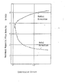
- the compressive strain should preferably exceed 0.05 when expressed by an absolute value of logarithmic strain. This is because, as will be described in more detail in examples, the billet prior to compression is rendered anisotropic in the direction of compression and thus a compressive strain of at least 0.05 is necessary so as to change the structure of the billet into a magnet having high magnetic characteristics in multipolar magnetization.
- the billet When the billet is made of a polycrystalline Mn-Al-C alloy magnet which has the direction of easy magnetization parallel to a plane vertical with respect to the axial direction of the hollow billet (i.e. plane-anisotropic permanent magnet), is magnetically isotropic within the plane, and is anisotropic in a direction of a perpendicular of the plane and within a plane including a straight line parallel to the first-mentioned plane, the billet prior to extrusion exhibits high magnetic charcteristics in all directions within a plane including radial and tangential directions. When compressed, the magnet can exhibit higher magnetic characteristics in multipolar magnetization.
- plane-anisotropic permanent magnet When compressed, the magnet can exhibit higher magnetic characteristics in multipolar magnetization.
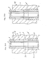
- Figs. 1(a) and l(b), respectively, show the states prior to and after compression.
- a part of die Q which includes a mandrel or core 1 having a section la of a larger diameter, a frusto-conical section 16 and a section 1c of a smaller diameter and a die ring 2 in a coaxially spaced relationship thereby establishing a cavity C therebetween.
- the cavity C includes a container portion 3, a bearing portion 4 and an intermediate portion 5.
- the dies Q has a punch 6 inserted between the section la and the die ring 2 and a punch 7 provided between the section 1c and the ring die 2.
- the container portion 3 is a portion where at least a part of a hollow cylindrical billet 8 prior to compressive working is accomodated and the bearing portion 4 is a portion where a billet 8' obtained after compressive working extrusion is received.
- a sectional area of the container portion almost corresponds to a sectional area of the billet 8 as seen from Fig. l(a).
- the sectional area of the bearing portion 4 almost corresponds to a sectional area of the billet 8' in Fig. l(b).
- the container and bearing portions are both circular in form and are formed around the extrusion core 1. Accordingly, the cavitied or sectional area of the container portion 3 is an area of a ring formed between outside and inside diameters of the container portion.
- the container 3 is in the form of a ring in section and can receives therein a hollow cylinder.
- the cavitied area of the bearing portion is an area of a ring in section formed between outside and inside diameters of the bearing portion 4.
- the cavitied areas of the container and bearing portions 3, 4 are, respectively, about 506 mm 2 and about 606 2 mm .
- the billet 8 In operation, when the punch 6 is moved downwards, the billet 8 is plastically deformed gradually at a portion in the bearing and intermediate portions 4, 5. A portion of the billet in the container portion is restrained or protected by the section la of the core 1 and the ring die 2 and does not deform. As the compression proceeds, the billet 8 in the intermediate and bearing portions is plastically deformed in directions vertical to the direction of the movement of the punch 6 and radially extends towards the side wall of the ring die 2 and the outer surface of the core 1. Although the portion in the container portion 3 is moved downwards, it suffers little deformation so far as existing in the container portion. In the case shown in Figs.1(a) and l(b), the punch 6 is not necessarily moved continuously but may be intermittently moved.
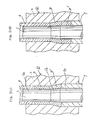
- the billet may be worked by a procedure as will be described with reference to Figs. 2(a) through 2(d).
- FIG. 2(a) Another embodiment according to the invention is described with reference to Figs. 2(a) through 2(d).
- a hollow cylindrical billet 8 is first placed in the bearing portion 4. Then, the billet 8' is compressed upwardly by the use of the punch 7. As a result, the billet is plastically deformed as shown in Fig. 2(b).
- a hollow cylindrical billet 8 to be worked is placed in the container portion 3 as shown in Fig. 2(c) and the billets 8, 8' are moved downwards from the container portion 3 toward the bearing portion 5 while compressing the billets by means of the punches 6, 7, by which the billets 8,8 ; are deformed as shown in Fig. 2(d).
- the billet 8 is removed from the bearing portion 5 and then a fresh billet is inserted into the container portion 3 as shown in Fig. 2(c), followed by repeating the steps shown in Figs. 2(c) and 2(d) to extrude hollow cylindrical billets one by one.
- the steps shown in Figs. 2(a) and 2(b), are not the step of extrusion according to the invention.
- the die shown in Figs. 2(a) through 2(d) has a cavitied area of the container portion 3 smaller than a cavitied area of the bearing portion.
- the die has the intermediate portion 5 in which the cavitied area gradually increases from the container portion 3 toward the bearing portion 4.
- the cavity of the intermediate portion 5 is merely filled with a billet for starting the working of the invention.
- the extrusion step shown in Figs. 2(c) and 2(d) embody the present invention.
- This embodiment involves a procedure in which the region of plastic deformation is continuously changed in relation to time.
- the billet 8 is completely restrained by the core 1 and the ring die 2 invariably over the entire process of manufacture. Accordingly, a fairly long billet may be used depending on the design of the die as will not be expected by prior art.
- the billets 8,8' When the billets 8,8' are moved toward the bearing portion 4 while compressing the billets between the punches 6 and 7, the billet 8' suffers the compressive strain produced 'in the direction of the extrusion.
- the hollow billet is moved at a rate of 0.05 to 30 mm/sec. in the practice of the invention.
- the billet prior to the extrusion is in the form of a cylinder.
- the billet In order to suppress compressive deformation of the billet in the container portion which is being compressed, the billet should be protected from opposite sides by the core and the ring die between which the billet is set. The billet is plastically deformed when entering the conical part.
- the section of the hollow cylindrical billet 8 which is a plane vertical to the axial direction of the billet and the section of the container portion are both in the form of rings.
- the anisotropic structure of a magnet obtained by the compressive working extrusion depends on the size of the billet prior to and after compression, i.e. the size parameter of the die. For instance, assuming that a billet prior to compression is in the form of a cylinder having an outer diameter of D oo , an inner diameter of D io and a height of h and a billet obtained after compression has an outer diameter of D o , an inner diameter of D. and a height of h, It may be said that when D o is smaller than D oo x , the resulting magnet has a direction of easy magnetization along radial directions.
- the resulting magnet has a direction of easy magnetization within a plane including radial and tangential directions. Moreover, when D o is larger than D oo x , a direction of easy magnetization becomes tangential. In short, smaller ratios of D o to D oo x result in magnets which are rendered more tangentially anisotropic.
- D oo x When the value of D oo x is kept constant, magnetic characteristics in the radial direction become higher than in the tangential direction at a small value of D o . As D o increases, the difference in magnetic characteristics between the tangential and radial directions becomes smaller. Over a certain value of D , higher magnetic characteristics in the tangential direction are obtained.
- magnets of different types of anisotropic structures can be obtained by suitably changing the sizes of the cavity portions of the die.
- the compressed portion can be changed in anisotropic structure to have a radial direction of easy magnetization.
- the plastic deformation is effected in a temperature range of 530 to 830°C. At temperatures exceeding 780°C, magnetic characteristics are found to decrease. Accordingly, a preferable temperature is in the range of 560 to 760°C.
- a charge composition comprising 69.5 wt% (hereinafter referred to simply as %) of Mn, 29.3% of Al, 0.5% of C and 0.7% of Ni were melted and cast in a mold thereby obtaining a solid cylindrical billet having a diameter of 70 mm and a length of 60 mm.
- the billet was maintained at 1100 0 C for 2 hours, followed by allowing to cool to room temperature. Thereafter, the billet was extruded through a lubricant at a temperature of 720°C to a level of 45 mm in diameter, followed by further extrusion through a lubricant at 680°C to a diameter of 31 mm.
- the resulting extruded rod was cut into pieces each having a length of 50 mm and machined to make several hollow cylindrical billets having an outer diameter of 30 mm, an inner diameter of 22 m and a length of 50 mm.
- These hollow billets were extruded at a temperature of 680°C using a die as shown in Fig. 1 according to the procedure illustrated with reference to FigS.2(a) through 2(d).
- a billet having an outer diameter of 32 mm, an inner diameter of 10 mm and a length of 22.5 mm which had been extruded according to the present invention was cut from the inside part of the billet to give a cubic body having each side of 5 mm, followed by measurement of magnetic characteristics. In the measurement, the individual sides were arranged parallel to axial, radial and tangential directions.
- the extruded billet had an outer diameter of 32 mm, an inner diameter of 10 mm and a length of 22.5 mm and was a sufficiently long magnet.
- the extruded rod having a diameter of 31 mm obtained in Example 1 was cut into pieces each having a length of 50 mm and machined to give several hollow cylindrical billets each having an outer diameter of 30 mm, an inner diameter of 15 mm and a length of 50 mm.
- Each billet was extruded at a temperature of 680°C through a lubricant using a die of the same type as shown in Fig. 1 in a manner illustrated with reference to Figs. 2(a) to 2(d).
- a cubic body having each side of 5 mm was cut from the extruded billet in such a way that the individual sides were parallel to axial, radial and tangential directions, followed by measurement of magnetic characteristics.
- the billet obtained after the extrusion has an outer diameter of 42 mm, an inner diameter of 21 mm and a length of 25 mm and was a sufficiently long magnet.
- the extruded rod having a diameter of 31 mm obtained in Example 1 was cut into a piece having a length of 50 mm and machined to give a hollow cylindrical billet having an outer diameter of 30 mm, an inner diameter of 10 mm and a length of 50 mm.
- the cylindrical billet was extruded at a temperature of 680°Cc through a lubricant using a die shown in Figs. l(a) and 1(b) by the procedure illustrated with reference to Figs. 2(a) through 2(d).
- the die had a container portion with an outside diameter of 30 mm and an inside diameter of 10 mm and a bearing portion with an outside diameter of 63.2 mm and an inside diameter of 49 mm.
- the billet after the extrusion had an outer diameter of 63.2 mm, an inner diameter of 49 mm and a length of 25 mm and was thus a long magnet.
- a cubic body having each side of 5 mm was cut from the outside part of the extruded billet in such a way that the individual sides were arranged parallel to axial, radial and tangential directions, followed by measurement of magnetic characteristics.
- a charge composition of 69.4% of Mn, 29.3% of A1, 0.5% of C, 0.7% of Ni and 0.1% of Ti was melted and cast to obtain a solid cylindrical billet having an outer diameter of 50 mm, an inner diameter of 20 mm and a length of 20 mm.
- This billet was kept at 1100°C for 2 hours and cooled in air to 600°C, followed by keeping at 600°C for 30 minutes and allowing to cool down to room temperature. Thereafter, the billet was extruded at 720°C through a lubricant using a die shown in Fig. 4.
- Fig. 4 indicated by 9, 10 and 6 are portions constituting a die used in known extrusion.
- portions of a die used in extrusion according to the invention are designated by 3, 5 and 4, respectively, which correspond a container portion, an intermediate portion and a bearing portion.
- the portion 9 had an outside diameter of 50 mm
- the portion 3 had an outside diameter of 30mm
- the portion 4 had an outside diameter of 36 mm with all the portions having an inside diameter of 20 mm.
- y 30 mm
- x 10 mm.
- the billet prior to extrusion was accomodated as 8 in Fig. 4 and was compressed by means of the punches 6 and 7, under which the billet was moved from the portion 9 toward bearing portion 4 through the intermediate portion 5 and extruded. In order to attain the state shown in Fig.
- a hollow cylindrical billet having approximately the same outer and inner diameters as the portion 9 and extruded using the punch 6. Further, a hollow cylindrical billet having approximately the same outer and inner diameters as the bearing portion 4 was accomodated in the bearing portion 4 and extruded by the use of the punch 7. By the extrusion from the opposite sides the entire cavity could be filled with the billets.
- the cylindrical billet after the extrusion was cut into pieces having a length of 20 mm and machined to obtain a hollow cylindrical magnet having an outer diameter of 35 mm and an inner diameter of 21mm.
- the cylindrical magnet was subjected to the 8-pole magnetization around the inner lateral surface.
- pulse magnetization was effect at 1500 V using an oil condenser of 2000 pF.
- the surface magnetic flux density on the inner lateral surface was measured by the Hall element. As a result, it was found that the density was in the range of 3.0 to 3.1 kG.
- Example 4 the combination of the step where a billet was previously rendered anisotropic as in Example 4 and the method of the invention can reduce or simplify the manufacturing process.
Landscapes
- Engineering & Computer Science (AREA)
- Power Engineering (AREA)
- Manufacturing & Machinery (AREA)
- Manufacturing Cores, Coils, And Magnets (AREA)
- Forging (AREA)
- Heat Treatment Of Nonferrous Metals Or Alloys (AREA)
- Hard Magnetic Materials (AREA)
Applications Claiming Priority (2)
| Application Number | Priority Date | Filing Date | Title |
|---|---|---|---|
| JP57065909A JPS58182207A (ja) | 1982-04-19 | 1982-04-19 | マンガン−アルミニウム−炭素系合金磁石の製造法 |
| JP65909/82 | 1982-04-19 |
Publications (3)
| Publication Number | Publication Date |
|---|---|
| EP0092423A2 true EP0092423A2 (de) | 1983-10-26 |
| EP0092423A3 EP0092423A3 (en) | 1985-02-06 |
| EP0092423B1 EP0092423B1 (de) | 1987-08-26 |
Family
ID=13300554
Family Applications (1)
| Application Number | Title | Priority Date | Filing Date |
|---|---|---|---|
| EP83302205A Expired EP0092423B1 (de) | 1982-04-19 | 1983-04-19 | Verfahren zur Herstellung von Permanentmagneten aus Mn-Al-C-Legierungen |
Country Status (4)
| Country | Link |
|---|---|
| US (1) | US4623404A (de) |
| EP (1) | EP0092423B1 (de) |
| JP (1) | JPS58182207A (de) |
| DE (1) | DE3373239D1 (de) |
Cited By (3)
| Publication number | Priority date | Publication date | Assignee | Title |
|---|---|---|---|---|
| GB2206241A (en) * | 1987-06-18 | 1988-12-29 | Seiko Epson Corp | Method of making a permanent magnet |
| US5538565A (en) * | 1985-08-13 | 1996-07-23 | Seiko Epson Corporation | Rare earth cast alloy permanent magnets and methods of preparation |
| US6136099A (en) * | 1985-08-13 | 2000-10-24 | Seiko Epson Corporation | Rare earth-iron series permanent magnets and method of preparation |
Families Citing this family (7)
| Publication number | Priority date | Publication date | Assignee | Title |
|---|---|---|---|---|
| JPS60133704A (ja) * | 1983-12-22 | 1985-07-16 | Matsushita Electric Ind Co Ltd | 永久磁石 |
| JPS61168903A (ja) * | 1985-01-22 | 1986-07-30 | Matsushita Electric Ind Co Ltd | 永久磁石 |
| JP4561974B2 (ja) * | 2004-09-01 | 2010-10-13 | 大同特殊鋼株式会社 | リング状磁石素材の製造方法 |
| US7325434B2 (en) * | 2004-09-01 | 2008-02-05 | Daido Tokushuko Kabushiki Kaisha | Method for manufacturing ring-shaped magnet material and manufacturing apparatus used therefor |
| JP4957415B2 (ja) * | 2006-09-06 | 2012-06-20 | 大同特殊鋼株式会社 | 永久磁石の製造方法および永久磁石 |
| JP2010259613A (ja) * | 2009-05-07 | 2010-11-18 | Liberal:Kk | 多極着磁した磁石を用いたブロック玩具 |
| JP6322911B2 (ja) * | 2013-07-05 | 2018-05-16 | 大同特殊鋼株式会社 | 非筒状の永久磁石の製造方法 |
Citations (5)
| Publication number | Priority date | Publication date | Assignee | Title |
|---|---|---|---|---|
| JPS5112319A (en) * | 1974-07-19 | 1976-01-30 | Matsushita Electric Ind Co Ltd | Mangan aruminiumu tansokeigokinjishakuno seizoho |
| DE2531120A1 (de) * | 1974-07-11 | 1976-04-15 | Matsushita Electric Ind Co Ltd | Verfahren zur herstellung anisotroper permanentmagneten aus mn-al-c- legierungen |
| EP0016960A1 (de) * | 1979-02-28 | 1980-10-15 | TDK Corporation | Anisotroper röhrenförmiger Polymermagnet und Verfahren zu dessen Herstellung |
| EP0034058A1 (de) * | 1980-02-07 | 1981-08-19 | Matsushita Electric Industrial Co., Ltd. | Verfahren zur Herstellung eines Permanentmagneten aus einer Mn-Al-C-Legierung |
| EP0092422A2 (de) * | 1982-04-19 | 1983-10-26 | Matsushita Electric Industrial Co., Ltd. | Dauermagnet aus Mn-Al-C-Legierung und Verfahren zu seiner Herstellung |
Family Cites Families (6)
| Publication number | Priority date | Publication date | Assignee | Title |
|---|---|---|---|---|
| US3266954A (en) * | 1960-01-12 | 1966-08-16 | Philips Corp | Process for making mnal permanent magnet having tetragonal phase |
| US4023991A (en) * | 1973-08-02 | 1977-05-17 | Matsushita Electric Industrial Co., Ltd. | Anisotropic permanent magnet of Mn-Al-C alloy |
| JPS5061698A (de) * | 1973-10-03 | 1975-05-27 | ||
| JPS5442342B2 (de) * | 1973-10-19 | 1979-12-13 | ||
| JPS5164916A (en) * | 1974-12-02 | 1976-06-04 | Matsushita Electric Ind Co Ltd | Supiika |
| JPS5914532B2 (ja) * | 1976-08-27 | 1984-04-05 | 松下電器産業株式会社 | 合金磁石 |
-
1982
- 1982-04-19 JP JP57065909A patent/JPS58182207A/ja active Granted
-
1983
- 1983-04-18 US US06/486,244 patent/US4623404A/en not_active Expired - Lifetime
- 1983-04-19 DE DE8383302205T patent/DE3373239D1/de not_active Expired
- 1983-04-19 EP EP83302205A patent/EP0092423B1/de not_active Expired
Patent Citations (5)
| Publication number | Priority date | Publication date | Assignee | Title |
|---|---|---|---|---|
| DE2531120A1 (de) * | 1974-07-11 | 1976-04-15 | Matsushita Electric Ind Co Ltd | Verfahren zur herstellung anisotroper permanentmagneten aus mn-al-c- legierungen |
| JPS5112319A (en) * | 1974-07-19 | 1976-01-30 | Matsushita Electric Ind Co Ltd | Mangan aruminiumu tansokeigokinjishakuno seizoho |
| EP0016960A1 (de) * | 1979-02-28 | 1980-10-15 | TDK Corporation | Anisotroper röhrenförmiger Polymermagnet und Verfahren zu dessen Herstellung |
| EP0034058A1 (de) * | 1980-02-07 | 1981-08-19 | Matsushita Electric Industrial Co., Ltd. | Verfahren zur Herstellung eines Permanentmagneten aus einer Mn-Al-C-Legierung |
| EP0092422A2 (de) * | 1982-04-19 | 1983-10-26 | Matsushita Electric Industrial Co., Ltd. | Dauermagnet aus Mn-Al-C-Legierung und Verfahren zu seiner Herstellung |
Non-Patent Citations (3)
| Title |
|---|
| CHEMICAL ABSTRACTS, vol. 84, no. 20, 17th May 1976, page 602, no. 143988y, Columbus, Ohio, USA; & JP - A - 76 12319 (MATSUSHITA ELECTRIC INDUSTRIAL CO., LTD.) 30-01-1976 * |
| IEEE TRANSACTIONS ON MAGNETICS, vol. MAG-17, no. 6, November 1981, pages 2651-2653, New York, USA; Z.A. ABDELNOUR et al.: "Permanent magnet properties of Mn-Al-C between -50 C and +150 C" * |
| JEE JOURNAL OF ELECTRON ENGINEERING, no. 127, July 1977, pages 50-54; T. KUBO et al.: "Anisotropic Mn-Al-C alloy permanent magnets can be machined and mass produced" * |
Cited By (7)
| Publication number | Priority date | Publication date | Assignee | Title |
|---|---|---|---|---|
| US5538565A (en) * | 1985-08-13 | 1996-07-23 | Seiko Epson Corporation | Rare earth cast alloy permanent magnets and methods of preparation |
| US5560784A (en) * | 1985-08-13 | 1996-10-01 | Seiko Epson Corporation | Rare earth cast alloy permanent magnets and methods of preparation |
| US5565043A (en) * | 1985-08-13 | 1996-10-15 | Seiko Epson Corporation | Rare earth cast alloy permanent magnets and methods of preparation |
| US5597425A (en) * | 1985-08-13 | 1997-01-28 | Seiko Epson Corporation | Rare earth cast alloy permanent magnets and methods of preparation |
| US6136099A (en) * | 1985-08-13 | 2000-10-24 | Seiko Epson Corporation | Rare earth-iron series permanent magnets and method of preparation |
| GB2206241A (en) * | 1987-06-18 | 1988-12-29 | Seiko Epson Corp | Method of making a permanent magnet |
| GB2206241B (en) * | 1987-06-18 | 1990-08-15 | Seiko Epson Corp | Method of making a permanent magnet |
Also Published As
| Publication number | Publication date |
|---|---|
| DE3373239D1 (en) | 1987-10-01 |
| EP0092423A3 (en) | 1985-02-06 |
| JPS58182207A (ja) | 1983-10-25 |
| JPH0311522B2 (de) | 1991-02-18 |
| EP0092423B1 (de) | 1987-08-26 |
| US4623404A (en) | 1986-11-18 |
Similar Documents
| Publication | Publication Date | Title |
|---|---|---|
| US4648915A (en) | Permanent Mn-Al-C alloy magnets | |
| US4623404A (en) | Method for making permanent magnets of Mn-Al-C alloys | |
| JPH037747B2 (de) | ||
| JPH0639675B2 (ja) | マンガン−アルミニウム−炭素系合金磁石の製造法 | |
| EP0034058B1 (de) | Verfahren zur Herstellung eines Permanentmagneten aus einer Mn-Al-C-Legierung | |
| JPH0311527B2 (de) | ||
| JPH0434804B2 (de) | ||
| JPH037745B2 (de) | ||
| JPS6210255A (ja) | マンガン−アルミニウム−炭素系合金磁石の製造法 | |
| JPS6210257A (ja) | マンガン−アルミニウム−炭素系合金磁石の製造法 | |
| JPS58192306A (ja) | マンガン−アルミニウム−炭素系合金磁石の製造法 | |
| JPH0311523B2 (de) | ||
| JPH06102819B2 (ja) | マンガン−アルミニウム−炭素系合金磁石の製造法 | |
| JPH0639674B2 (ja) | マンガン−アルミニウム−炭素系合金磁石の製造法 | |
| JPS61166957A (ja) | マンガン−アルミニウム−炭素系合金磁石の製造方法 | |
| JPH0639673B2 (ja) | マンガン−アルミニウム−炭素系合金磁石の製造法 | |
| JPH0311525B2 (de) | ||
| JPH0311521B2 (de) | ||
| JPS61187213A (ja) | 合金磁石の製造法 | |
| JPH0434807B2 (de) | ||
| JPS61166959A (ja) | マンガン−アルミニウム−炭素系合金磁石の製造方法 | |
| JPS62112765A (ja) | マンガン−アルミニウム−炭素系合金磁石の製造法 | |
| JPH037748B2 (de) | ||
| JPH0639667B2 (ja) | マンガン−アルミニウム−炭素系合金磁石の製造法 | |
| JPS6210253A (ja) | マンガン−アルミニウム−炭素系合金磁石の製造法 |
Legal Events
| Date | Code | Title | Description |
|---|---|---|---|
| PUAI | Public reference made under article 153(3) epc to a published international application that has entered the european phase |
Free format text: ORIGINAL CODE: 0009012 |
|
| AK | Designated contracting states |
Designated state(s): DE FR GB NL |
|
| PUAL | Search report despatched |
Free format text: ORIGINAL CODE: 0009013 |
|
| AK | Designated contracting states |
Designated state(s): DE FR GB NL |
|
| 17P | Request for examination filed |
Effective date: 19850329 |
|
| 17Q | First examination report despatched |
Effective date: 19860207 |
|
| GRAA | (expected) grant |
Free format text: ORIGINAL CODE: 0009210 |
|
| AK | Designated contracting states |
Kind code of ref document: B1 Designated state(s): DE FR GB NL |
|
| ET | Fr: translation filed | ||
| REF | Corresponds to: |
Ref document number: 3373239 Country of ref document: DE Date of ref document: 19871001 |
|
| PLBE | No opposition filed within time limit |
Free format text: ORIGINAL CODE: 0009261 |
|
| STAA | Information on the status of an ep patent application or granted ep patent |
Free format text: STATUS: NO OPPOSITION FILED WITHIN TIME LIMIT |
|
| 26N | No opposition filed | ||
| REG | Reference to a national code |
Ref country code: GB Ref legal event code: 746 Effective date: 19951123 |
|
| REG | Reference to a national code |
Ref country code: FR Ref legal event code: D6 |
|
| PGFP | Annual fee paid to national office [announced via postgrant information from national office to epo] |
Ref country code: FR Payment date: 19990409 Year of fee payment: 17 |
|
| PGFP | Annual fee paid to national office [announced via postgrant information from national office to epo] |
Ref country code: GB Payment date: 19990421 Year of fee payment: 17 |
|
| PGFP | Annual fee paid to national office [announced via postgrant information from national office to epo] |
Ref country code: DE Payment date: 19990426 Year of fee payment: 17 |
|
| PG25 | Lapsed in a contracting state [announced via postgrant information from national office to epo] |
Ref country code: GB Free format text: LAPSE BECAUSE OF NON-PAYMENT OF DUE FEES Effective date: 20000419 |
|
| PGFP | Annual fee paid to national office [announced via postgrant information from national office to epo] |
Ref country code: NL Payment date: 20000428 Year of fee payment: 18 |
|
| GBPC | Gb: european patent ceased through non-payment of renewal fee |
Effective date: 20000419 |
|
| PG25 | Lapsed in a contracting state [announced via postgrant information from national office to epo] |
Ref country code: FR Free format text: LAPSE BECAUSE OF NON-PAYMENT OF DUE FEES Effective date: 20001229 |
|
| PG25 | Lapsed in a contracting state [announced via postgrant information from national office to epo] |
Ref country code: DE Free format text: LAPSE BECAUSE OF NON-PAYMENT OF DUE FEES Effective date: 20010201 |
|
| REG | Reference to a national code |
Ref country code: FR Ref legal event code: ST |
|
| PG25 | Lapsed in a contracting state [announced via postgrant information from national office to epo] |
Ref country code: NL Free format text: LAPSE BECAUSE OF NON-PAYMENT OF DUE FEES Effective date: 20011101 |
|
| NLV4 | Nl: lapsed or anulled due to non-payment of the annual fee |
Effective date: 20011101 |