EP0091713B1 - Verfahren zur Herstellung druckfrischer, auf Format geschnittener Wertscheine und automatische Schneidmaschine zur Durchführung des Verfahrens - Google Patents
Verfahren zur Herstellung druckfrischer, auf Format geschnittener Wertscheine und automatische Schneidmaschine zur Durchführung des Verfahrens Download PDFInfo
- Publication number
- EP0091713B1 EP0091713B1 EP83200473A EP83200473A EP0091713B1 EP 0091713 B1 EP0091713 B1 EP 0091713B1 EP 83200473 A EP83200473 A EP 83200473A EP 83200473 A EP83200473 A EP 83200473A EP 0091713 B1 EP0091713 B1 EP 0091713B1
- Authority
- EP
- European Patent Office
- Prior art keywords
- feed
- cutting
- strips
- sheets
- cut
- Prior art date
- Legal status (The legal status is an assumption and is not a legal conclusion. Google has not performed a legal analysis and makes no representation as to the accuracy of the status listed.)
- Expired
Links
- 238000005520 cutting process Methods 0.000 title claims description 114
- 238000000034 method Methods 0.000 title claims description 33
- 238000004519 manufacturing process Methods 0.000 title claims description 3
- 238000007639 printing Methods 0.000 claims description 81
- 238000009966 trimming Methods 0.000 claims description 19
- 239000002699 waste material Substances 0.000 claims description 16
- 239000011159 matrix material Substances 0.000 claims description 3
- 238000012937 correction Methods 0.000 description 13
- 238000012545 processing Methods 0.000 description 8
- 230000008901 benefit Effects 0.000 description 7
- 230000008859 change Effects 0.000 description 7
- 238000005259 measurement Methods 0.000 description 4
- 230000008569 process Effects 0.000 description 4
- 229910000831 Steel Inorganic materials 0.000 description 3
- 230000000694 effects Effects 0.000 description 3
- 239000010959 steel Substances 0.000 description 3
- 230000009471 action Effects 0.000 description 2
- 230000007423 decrease Effects 0.000 description 2
- 238000007689 inspection Methods 0.000 description 2
- 230000001419 dependent effect Effects 0.000 description 1
- 238000011161 development Methods 0.000 description 1
- 238000007646 gravure printing Methods 0.000 description 1
- 238000009434 installation Methods 0.000 description 1
- 230000007246 mechanism Effects 0.000 description 1
- 239000002184 metal Substances 0.000 description 1
- 238000007645 offset printing Methods 0.000 description 1
- 230000003287 optical effect Effects 0.000 description 1
- 238000004806 packaging method and process Methods 0.000 description 1
- 239000010893 paper waste Substances 0.000 description 1
- 238000003825 pressing Methods 0.000 description 1
- 108090000623 proteins and genes Proteins 0.000 description 1
- 238000003908 quality control method Methods 0.000 description 1
- 230000004044 response Effects 0.000 description 1
- 230000000007 visual effect Effects 0.000 description 1
- 238000011179 visual inspection Methods 0.000 description 1
Images
Classifications
-
- B—PERFORMING OPERATIONS; TRANSPORTING
- B26—HAND CUTTING TOOLS; CUTTING; SEVERING
- B26D—CUTTING; DETAILS COMMON TO MACHINES FOR PERFORATING, PUNCHING, CUTTING-OUT, STAMPING-OUT OR SEVERING
- B26D7/00—Details of apparatus for cutting, cutting-out, stamping-out, punching, perforating, or severing by means other than cutting
- B26D7/01—Means for holding or positioning work
- B26D7/015—Means for holding or positioning work for sheet material or piles of sheets
-
- B—PERFORMING OPERATIONS; TRANSPORTING
- B41—PRINTING; LINING MACHINES; TYPEWRITERS; STAMPS
- B41F—PRINTING MACHINES OR PRESSES
- B41F17/00—Printing apparatus or machines of special types or for particular purposes, not otherwise provided for
-
- B—PERFORMING OPERATIONS; TRANSPORTING
- B41—PRINTING; LINING MACHINES; TYPEWRITERS; STAMPS
- B41F—PRINTING MACHINES OR PRESSES
- B41F33/00—Indicating, counting, warning, control or safety devices
-
- B—PERFORMING OPERATIONS; TRANSPORTING
- B65—CONVEYING; PACKING; STORING; HANDLING THIN OR FILAMENTARY MATERIAL
- B65H—HANDLING THIN OR FILAMENTARY MATERIAL, e.g. SHEETS, WEBS, CABLES
- B65H2301/00—Handling processes for sheets or webs
- B65H2301/40—Type of handling process
- B65H2301/42—Piling, depiling, handling piles
- B65H2301/422—Handling piles, sets or stacks of articles
- B65H2301/4229—Handling piles, sets or stacks of articles cutting piles
-
- B—PERFORMING OPERATIONS; TRANSPORTING
- B65—CONVEYING; PACKING; STORING; HANDLING THIN OR FILAMENTARY MATERIAL
- B65H—HANDLING THIN OR FILAMENTARY MATERIAL, e.g. SHEETS, WEBS, CABLES
- B65H2301/00—Handling processes for sheets or webs
- B65H2301/40—Type of handling process
- B65H2301/43—Gathering; Associating; Assembling
- B65H2301/431—Features with regard to the collection, nature, sequence and/or the making thereof
- B65H2301/4314—Making packets of bundles of banknotes or the like in correct sequence
-
- B—PERFORMING OPERATIONS; TRANSPORTING
- B65—CONVEYING; PACKING; STORING; HANDLING THIN OR FILAMENTARY MATERIAL
- B65H—HANDLING THIN OR FILAMENTARY MATERIAL, e.g. SHEETS, WEBS, CABLES
- B65H2701/00—Handled material; Storage means
- B65H2701/10—Handled articles or webs
- B65H2701/19—Specific article or web
- B65H2701/1912—Banknotes, bills and cheques or the like
-
- Y—GENERAL TAGGING OF NEW TECHNOLOGICAL DEVELOPMENTS; GENERAL TAGGING OF CROSS-SECTIONAL TECHNOLOGIES SPANNING OVER SEVERAL SECTIONS OF THE IPC; TECHNICAL SUBJECTS COVERED BY FORMER USPC CROSS-REFERENCE ART COLLECTIONS [XRACs] AND DIGESTS
- Y10—TECHNICAL SUBJECTS COVERED BY FORMER USPC
- Y10T—TECHNICAL SUBJECTS COVERED BY FORMER US CLASSIFICATION
- Y10T83/00—Cutting
- Y10T83/141—With means to monitor and control operation [e.g., self-regulating means]
- Y10T83/148—Including means to correct the sensed operation
-
- Y—GENERAL TAGGING OF NEW TECHNOLOGICAL DEVELOPMENTS; GENERAL TAGGING OF CROSS-SECTIONAL TECHNOLOGIES SPANNING OVER SEVERAL SECTIONS OF THE IPC; TECHNICAL SUBJECTS COVERED BY FORMER USPC CROSS-REFERENCE ART COLLECTIONS [XRACs] AND DIGESTS
- Y10—TECHNICAL SUBJECTS COVERED BY FORMER USPC
- Y10T—TECHNICAL SUBJECTS COVERED BY FORMER US CLASSIFICATION
- Y10T83/00—Cutting
- Y10T83/525—Operation controlled by detector means responsive to work
- Y10T83/536—Movement of work controlled
-
- Y—GENERAL TAGGING OF NEW TECHNOLOGICAL DEVELOPMENTS; GENERAL TAGGING OF CROSS-SECTIONAL TECHNOLOGIES SPANNING OVER SEVERAL SECTIONS OF THE IPC; TECHNICAL SUBJECTS COVERED BY FORMER USPC CROSS-REFERENCE ART COLLECTIONS [XRACs] AND DIGESTS
- Y10—TECHNICAL SUBJECTS COVERED BY FORMER USPC
- Y10T—TECHNICAL SUBJECTS COVERED BY FORMER US CLASSIFICATION
- Y10T83/00—Cutting
- Y10T83/647—With means to convey work relative to tool station
- Y10T83/6476—Including means to move work from one tool station to another
- Y10T83/6489—Slitter station
- Y10T83/6491—And transverse cutter station
Definitions
- the invention relates to a method according to the preamble of claim 1 and to an automatic cutting machine for performing the method according to DE-A-2757186.
- notes of sheet with a certain number of benefits that is to say with a certain number of security prints arranged in a matrix
- these sheets are stacked step by step in strip layers and then the strip layers in bundles of notes cut, whereby the individual notes of the bundle receive their finished format.
- the feed lengths for the step-by-step feed of the sheet stacks and the strip positions are fixed based on a feed program that has been set once, depending on the size of the banknotes or the desired bill format.
- the accrued, cut vouchers are of course all the same size. This uniform size of notes is advantageous for the automatic further processing, sorting and packaging of the bundles of notes.
- the printed image of a note is always centered within the edges of the note or, as is said, always exactly in the mirror.
- the security print includes direct gravure printing, in particular a steel engraving print, in which the printing plates are subjected to a very high contact pressure and undergo a gradual expansion under the action of these forces during operation, that is to say become increasingly longer and also wider, this widening becoming larger along the pressure plate in the direction opposite to the direction of rotation of the plate cylinder.
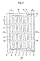
- the schematic shape of such a deformed, approximately trapezoidal printing plate corresponds to the outline 11 'in FIG. 2, which will be explained in more detail later.
- the size and positions of the prints change, so that the sheet stacks are cut automatically with constant feed lengths
- Completely cut notes of value are created, in which the printed image moves more and more out of its centered position with increasing number of prints and therefore the difference in the widths of the margins becomes more and more striking.
- the invention has for its object to provide a method which, despite a printing plate deformation occurring in the course of operation, always allows you to obtain coupons when the sheet stacks are cut, which have at least approximately centered printed images with respect to the edges of the coupons.
- the change in the feed lengths can be carried out manually on the basis of an experience program which has been set up empirically and possibly also theoretically for the printing plates in question.
- the lengths of the feed movements can be changed and adjusted accordingly.
- the readjustments to be made to the original feed program can also be carried out on the basis of a regular inspection and measurement of the printing plate, for example after every 50,000 or 100,000 prints.
- a change in length of the individual feeds can be carried out particularly precisely and easily with commercially available feed devices, which are known under the name linear amplifier.
- These linear amplifiers have a hydraulic cylinder-piston system, the metered pressure medium supply to the hydraulic cylinder being carried out with the aid of a stepper motor which briefly opens the pressure medium inlet valve with each revolution; as a result, a precisely metered, small amount of pressure medium is supplied to the cylinder during one revolution of the stepping motor in such a way that the piston carries out a feed of, for example, 0.1 mm.
- Such a hydraulically controlled feed also works with a sufficiently short response time.
- a preferred embodiment of the method according to the invention is to apply printing marks on the printing plate, which define the later cutting lines and inevitably take part in the deformations of the printing plate, and to control the feed devices by reading devices which read the markings made during the printing process. These markings are printed on the edges of the sheets and, if appropriate, on the areas lying between the printed images, which are cut off as waste strips during later sheet edge trimming or later intermediate cuts.
- the cutting dimension Automatically control the machine as a function of the positions of these print markings so that banknotes are always cut whose print image is centered correctly or at least much more precisely than before.
- the change in the feed lengths when cutting naturally means that, if one does not make intermediate cuts, the finished cut notes of value vary slightly in size, depending on the deformation of the printing plates.
- the advantage achieved namely that the printed image of the notes of value is always at least approximately exactly in the mirror, is to be rated much higher than the somewhat different size of the notes of value obtained.
- This changing size is in fact not noticeable in practice and could at best be determined by exact measurements of several notes of value; the slightly different size of the banknotes is practically negligible when it is processed into packaged bundle packages. In contrast, an incorrectly centered printed image immediately notices the viewer of a note.
- the deformation effect of the base plate is more important in the longitudinal direction than in the transverse direction, so that under certain circumstances the feed lengths only need to be changed for the strip cuts made parallel to the gripper edge and centering correction can be dispensed with for the ribbon cuts.
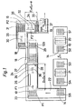
- FIG. 1 schematically shows those processing stations at which method steps according to the invention take place. It is assumed that the coupons have already been printed on both sides in offset printing and also on one side in steel engraving. The last printing process for the note sheets prepared in this way is that the other sheet side is also printed with an engraved image.
- the engraving printing unit 20 provided for this purpose is indicated schematically in FIG. 1.
- the individual, fully printed sheets 10 each have 24 security impressions or so-called individual benefits, which are arranged in a matrix in six rows with four security impressions each.
- Fig. 2 such a sheet 10 is shown enlarged with its six rows of bills 1 to 6; the banknotes later cut to format are designated by 12 and the actual banknote impressions surrounded by an unprinted border are designated by 13.
- the individual sheets are pulled by sheet grippers which hold the front sheet edge as they pass through the printing units.
- This sheet edge lying at the front as it passes through the printing units in the transport direction F o is the so-called gripper edge 14 (FIGS. 1 and 2), and the value rows 1 to 6 are parallel to this gripper edge 14, that is to say transversely to the direction of the sheet passing through the printing units, oriented.
- the remaining three sheet edges are labeled 15, 16 and 17.
- the finished printed sheets 10 of the stack S2 are usually subjected to a visual quality control, in which sheets are discarded with misprints, and then by one for numbering the individual uses Input stack S3 is entered into a numbering machine 21 and stored at its output on an output stack S4.
- a sheet stack S5 is first transported in the direction of the arrow along a transport path 22 to the entrance of a cutting path 24 and brought into a defined starting position P1, in which all sheets 10 of the stack are aligned with their gripper edges 14 at a stop 23.
- the gripper edges 14 form the trailing edge of the sheet and thus the reference edge of the sheet stack which is decisive for the strip cut, on which finger-like slides are known an automatic feed device 26 to feed the stacks.
- the edge of the sheet is cut here which forms the rear edge of the strip layers during the later bundle cut, that is, in the example considered, the left side edge 15 of the sheet 10 in the feed direction.
- the strip cutter 27 designed as a cross cutter, the edge is first cut at the front of the stack of the front edge 16 of the sheet 10 (FIG. 2), then the stack is divided step by step into its six strip layers 18, which correspond to the six value rows 1 to 6, and finally the rear edge trim is on the back of the last strip layer the gripper edge 14 executed.
- the waste paper from the edge trimmings falls through a waste flap. When a stack is cut, the following stack is automatically fed.
- a banding station 29 with a number of individual banding devices corresponding to the number of blanks per strip, in the example considered four banding devices that are operated simultaneously in each work step, in such a way that each layer of strips 18 is simultaneously connected to the four note or Benefit positions with a pre-glued band 129 is surrounded.
- the finished banded strip layers 18 are first removed from the banding station 29 in the direction of the arrow in the longitudinal direction of the strip and then moved along the transport path 35, transversely to the longitudinal direction of the strip, by means of a feed device 30 to the entrance of the cutting path 36, on which an automatic bundle cutting unit 33 designed as a cross cutting unit is installed.
- a feed device 30 to the entrance of the cutting path 36, on which an automatic bundle cutting unit 33 designed as a cross cutting unit is installed.
- all six strip layers 18 belonging to one and the same sheet stack S5 are collected in a defined starting position P2, in which the edges trimmed in the longitudinal cutting device 25 are aligned by abutment against a stop which is formed by the slide system 31 of the feed direction 32 .
- the feed device 32 While previously known installations provide a single feed device with a slide which is common to all the strip layers, the feed device 32 according to the invention, as will be explained later, consists of a number of individual feed devices corresponding to the number of strip layers 18 per stack with slides individually moving the strip layers . All six strip layers 18 belonging to a sheet stack, which, as indicated in FIG. 1, are arranged next to each other at a small distance, are then moved together by means of the feed device 32 in the direction of arrow F2 to the bundle cutting device 33, wherein they are guided in grooves. In the bundle cutter 33, the front edge of all the strip layers 18 corresponding to the sheet side edge 17 (FIG.
- the banded bundles 19 cut to format are advanced to a transport path 37 and arrive at further processing stations which are not of interest here, in which bundle packages with consecutively numbered notes of a particular series are formed and these bundle packages are then banded and packaged.
- This further processing is the subject of, for example, the Swiss patent specification CH 577 426 and the American patent specifications US 3939621 and 4,045,944 by the same applicant.
- the originally set, constant feeds D o , a, E o , and b are used.
- the outline 11 of the overall printing image (including the later value edges) shown in FIG. 2 is, of course, exactly rectangular, corresponding to the exact original geometry and arrangement of the engraving pits of the printing plates, and that in FIG. 2 is also rectangular
- Security impressions 13 shown are all undistorted and of the same size and are always centered after the sheet 10 has been cut into security notes 12 with the same format axb along the dashed cut line, always centered with respect to the unprinted value border.
- the printing plates now expand under the action of the contact forces which are exerted by the printing cylinder during each printing process.
- This deformation is particularly strong in the case of an engraving printing plate, since a particularly high pressure must be used in steel engraving printing.
- the lengthening and widening takes place in a non-linear manner, so that the printing surface assumes an approximately trapezoidal shape, the rear printing plate edge as seen in the direction of rotation of the plate cylinder forming the base side of the trapezoid.
- the outline 11 ' which delimits the area of the total printed image of all the security impressions of a sheet 10 and is shown in broken lines in FIG. 2, and each individual security impression are distorted approximately in a trapezoidal shape.
- the total print image in direction F1 is extended by the amount d compared to its original dimension, which was 6a.
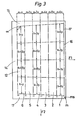
- a sheet 10 the print image of which is distorted and has the outline 11 ', is shown in FIG. 3.
- those lines are drawn in dashed lines in FIG. 3 which would have to form the cut lines in the later strip and bundle cut, so that despite the distortion in all manufactured notes, the security impressions (not shown in FIG. 3) are at least approximately in the mirror, i. H. are centered in relation to the unprinted value border.
- the dimensions of the individual blanks oriented in the direction of F2, that is to say parallel to the gripper edge 14 (that is to say the security impressions including their unprinted border) take along each of the rows of tokens 1 to 6, starting with one compared to the original one Dimension b increased value, first from time to time and then further and from row of banknotes to banknotes, viewed in direction F1, successively larger.
- the individual benefits located at the ends of the value row 6 have a dimension b + y enlarged by the amount y, while the two middle individual benefits are only extended to b + 0.5.
- the two individual uses at the ends have the dimension b + 2y and the two middle ones have the dimension b + y.
- the two individual uses at the ends have the dimension b + 3y and the two middle ones have the dimension b + 1.5y.
- the outer individual uses have the dimensions b + 4y, b + 5y and b + 6y and the middle ones have the dimensions b + 2y, b + 2.5y and b + 3y.
- the values x and y after 100,000 prints can be, for example, approximately 0.05 mm each, so that the extension d of the total printed image of a sheet (FIG. 1) is approximately 1 mm. If the sheet stacks are cut as before with constant feed lengths, i.e. along the dashed lines in FIG. 1, then the printed image 13 of the banknotes 12 is practically still centered within the row of banknotes 6 within the unprinted banknotes border, but all others point Notes have a more or less shifted print image from their central position, whereby these centering errors are greatest for the notes of the value series 1 and of course become stronger and more conspicuous with an increasing number of prints.
- the correction for the strip cut should be considered.
- pressure markings are provided on the engraving printing plate, which define the later cutting lines and inevitably change their position as the printing plate expands.
- these markings are also printed on one side edge 17 of each sheet and, in the example considered (FIGS. 2 and 3), consist of line-shaped markings m which are assigned to the cutting line parallel to the gripper edge 14. These markings are read immediately before the sheet stacks enter the strip cutting unit 27 by a reading device 28 (FIG. 1), which brings the sheet stacks to a standstill in the intended cutting position.
- the distance of the reader 28 from the knife of the strip cutter 27 and the positions of the markings m relative to the cutting lines assigned to them are selected such that after the feed device 26 has been switched off when the reader 28 is activated, a sheet stack arises due to its inertia and the inertia of the Feed mechanism just moved into the desired cutting position and comes to a standstill there.
- This braking distance or run-out distance of a stack is a defined size that can be reproduced exactly for the same stack.
- the following markings m precisely control the sequence of the progressively smaller feed steps, in the example according to FIG. 3 the feed steps a + 6x, a + 5x, etc. to a + x.
- the easy-to-implement markings to be printed and their automatic reading by a reading device 28 controlling the feed device 25 therefore permit constant exact control of the feed lengths when cutting strips as a function of the constantly increasing pressure plate deformation.
- double markings can also be provided, which, as indicated in FIG. 3, consist of two line-shaped markings m s and m located at a short distance from one another.
- the arrangement is then such that when the first mark m s is read, the normal feed speed of the sheet stacks is reduced to a creeping movement and the feed device is only switched off when the second mark m is read.
- the preceding braking of the sheet stacks before they are stopped in this way increases the running accuracy into the cutting position and is expedient when the sheet stacks are pushed forward in the usual way, as described, by means of sliders which only abut the rear edge of the stack.
- this side edge trimming is not always carried out exactly at a right angle to the gripper edge 14 (FIG. 1), but rather along the side boundary 15 Line of the trapezoidal outline 11 'of the overall printed image; this line of intersection includes the angle a with the gripper edge 14 (FIG. 3), which becomes greater than 90 ° with the onset of distortion and increases with increasing pressure plate expansion.
- the longitudinal cutting device 25 or its knife can be rotated about a vertical axis in such a way that the cutting angle tt relative to the gripper edge 14, starting from an originally right angle, can be made ever larger during operation.
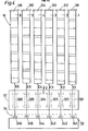
- the slides 311 to 316 of the feed devices 321 to 326 are also set more and more obliquely in the course of operation, so that they are always oriented parallel to the rear edge of the strip layers 18 and thus lie snugly against them in order to ensure a well-defined feed.
- the slides 311 to 316 can be pivoted about vertical axes within a sufficient angle.
- this cutting angle ex of the slitter 25 can be controlled automatically.
- the cutting angle is changed as a function of the increasing distortion, as explained, which in the simplest case can be carried out by hand in such a way that after the passage of, for example, 50,000 to 100,000 sheets each, corresponding to 500 to 1000 stacks with 100 sheets each, based on a visual inspection and measurement of the printed images or the stretched printing plate.
- This can be a local pattern, a certain color range or a striking contrast, preferably the contrast between the light, unprinted value border and a dark area of the value print.
- a characteristic point in particular a sufficient contrast at the limit of the printed value of the banknote, can be found practically on all banknotes and can be used as a natural marking selectively recognizable by a reading device, which defines the adjacent cutting line.
- readers with the required selectivity are readily available or are easily adaptable.
- reading windows can be used in a known manner, as is done, for example, when reading register marks in printing machines.
- the characteristic locations to be read for controlling the feeds can also be fluorescence areas provided on the bill of value.
- these characteristic points can also be non-optical properties, for example metal threads or the like embedded in the note paper, to which suitable detectors respond.
- the mark for the feed control during the bundle cut is the contrast between the light value note border lying in the direction of F2 and the dark printed image of each individual use on each of the strip layers 18.
- a reader system 34 with the six readers 341 to 346 (FIG. 4) is installed in front of the bundle cutter 33, which individually scan the individual strip layers 18, corresponding to the six rows of notes 1 to 6, and the feed devices 321 that move these strip layers control up to 326 individually. Starting from the aligned starting position P2, the six strip layers 18 are advanced together, which are of different lengths on their rear edges because of the somewhat oblique edge trim, as illustrated in FIG. 4.
- the reader 341 first responds to the first contrast point of the strip position corresponding to the bank note row 1, that is to say to the front boundary of the first printed security image, and therefore switches off the feed device 321.
- the arrangement is such that the strip position then comes to a standstill after a total feed length E1 in the first desired cutting position, in which the front edge of the strip layer is trimmed.
- the feed lengths of the remaining strip positions which correspond to the value note rows 2 to 6 and which are correspondingly controlled by the readers 342 to 346, increase successively and are designated in FIG. 4 by E2, E3, E4, E5 and E6.
- E E o - e i applies, whereby the index i refers to one of the six value series 1 to 6 and can accordingly assume the values 1 to 6.
- the feed device 321 which measures the sum of the four feed steps covered in the bundle cuts of the strip position ; this sum, 4b + 18y in the example under consideration, corresponds precisely to the required length dimension, from which the cutting angle ⁇ can be derived on the basis of the relationship mentioned.
- the measured value supplied by the measuring device 351 is therefore fed to a suitably programmed mini-computer or microprocessor, which calculates the associated value of the angle, x and issues a control command for correspondingly controlling the cutting position of the longitudinal cutting device 25.
- a suitably programmed mini-computer or microprocessor which calculates the associated value of the angle, x and issues a control command for correspondingly controlling the cutting position of the longitudinal cutting device 25.
- other methods for measuring the respective distortion state of the overall printed image 11 'and for automatically evaluating the measurement results for the purpose of controlling the desired cutting angle are also possible.
- reading devices are dispensed with and the control is carried out with the aid of a mini computer or microprocessor, depending on the feed values covered in each case in the strip cut.
- a mini computer or microprocessor Use is made of the theoretically and / empirically determinable relationship that exists between the elongation in the longitudinal direction and the transverse direction for a given printing plate. If a characteristic strain value in the direction of F1 (FIG. 3) is known, then the corresponding strain in the direction of F2 can be calculated on the basis of this relationship, or at least can be estimated with sufficient accuracy for the present purposes.
- a measuring device 36 which is indicated schematically in FIG.
- This second embodiment requires only a reader 28 for reading the markings defining the strip cuts and for controlling the strip cutting unit 27, as well as a correspondingly programmed mini-computer or microprocessor, to which the measured feed lengths of the feed device 26 are entered as measured values and which controls the described individual feeds for the bundle cut; at the same time, in this case, he preferably also controls the setting of the longitudinal cutting unit 25 to the respective cutting angle a, which also results from the relationship or programming mentioned.
- the measuring device for measuring the feed paths covered can simply consist of a rev counter, which measures the number of revolutions carried out by the stepper motor mentioned.
- a feed path covered by the feed device can also be determined in another way, for example optically by measuring the distance covered by a sheet stack or a strip position.
- a third embodiment of the method it is also possible to dispense with printing markings and readers in such a way that all feeds, both in the case of strip cutting and bundle cutting, are controlled by a computer which has been given a program which detects the increasing elongation of the printing plate in question as a function of Describes the number of prints.
- the course of the expansion of a particular Druckpla t tentyps with the number of prints can be performed mathematically and / or empirically determined or based on experience and establish therefrom a complete program for the feed control.
- the programmable feed devices 26 and 32 are initially set in the usual way to the constant original feed values D o , a, E o and b and are always re-programmed by hand in the course of operation as soon as the centering error that arises becomes noticeable to the naked eye or begins to become disruptive.
- the distortion effects produced by the printing plate stretching in the transverse direction are less disturbing than those in the longitudinal direction (direction F o ), because namely the widening in the transverse direction takes place symmetrically on both sides and therefore the security impressions in the central region of the sheets are only relatively slight after the one and shifted to the other side and the laterally outer security prints experience a shift that only corresponds to approximately half of the overall widening of the overall printed image 11 '.
- the distortion effects add up in the individual value rows 6 to 1 of a sheet in the longitudinal direction, that is to say in the direction F1, as the example according to FIGS. 2 and 3 illustrates. For this reason, it may be sufficient to apply the feedrate correction described only for strip cutting and, as usual, to work with constant feed rates for bundle cutting.
- the correction options described above for the strip cut and for the bundle cut can also be combined in any way, for example in such a way that the feed control takes place fully automatically during the strip cut, while the feed program for the bundle cut is changed by hand as required.
- the accuracy of the centering of the security prints within their border not only depends on the printing plate stretching, but is subject to more or less large tolerances, which essentially depend on differences in the format of the note sheets, on the pressing and stretching of the paper during printing and come from its moisture content and from inaccuracies when cutting. It would therefore be useless to introduce feed corrections that are more precise than the tolerances mentioned, to which the centering of the security notes is subject for other reasons.
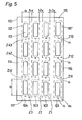
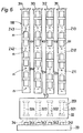
- FIGS. 5 and 6 show a bill of value 110 with 16 individual bills 112, which are arranged in four rows of bills 101 to 104 of four individual bills each. It is assumed that the engraving printing plate, which has printed this sheet, has undergone a noticeable stretching, as in the example according to FIGS. 2 and 3, so that the outline 111 'of the total printed image of all security impressions 113 is again distorted approximately trapezoidally.
- print markings m are provided on the side edge 117, which are read by the reader 28 for feed control during strip cutting, and on the other hand print markings n, which are printed on the intermediate strip between adjacent individual uses of each row of notes and can be read from the readers 341 to 344 (FIG. 6) for the purpose of feed control during the bundle cut of the individual strip layers 118.
- All printing markings m and n define the widths of the front edges and intermediate strips to be cut, which are variable as a result of the printing plate expansion.
- the front edge 116 is first cut off in the strip cutter 27, the feed into this cutting position being controlled by the reading device 28 by reading the first pressure marking m .
- the length a of the following feed step into the cutting position required for the first strip cut is pre-programmed.
- the feed into the following sectional position, in which the intermediate strip Z1 is cut off, is in turn controlled by the reading device 28 by reading the second print mark m. This is followed by a feed step of length a, and so on.
- the feed device 32 for the four strip layers (118) belonging to a stack again comprises feed devices 321 to 324 individually assigned to these strip layers with their slides 311 to 314.
- each of the feed devices 321 to 324 carries out a permanently programmed feed step of length b, whereupon the foremost bundles of notes of each strip layer are cut off.
- the next feed is in turn controlled by the reading devices, individually for each strip position, when reading the respective marking n on the intermediate strips Z11, Z21, Z31 and Z41, whereupon these strip layers are cut off together. This cut is followed by a programmed feed step of length b, etc.
- the described feed control when working with intermediate cuts can also be carried out either according to a prepared program that changes as a function of the printing plate expansion or by hand, as is the case for the example according to FIGS. 2 to 4 has been described.
- feed control by reading devices it is also possible, without special printing markings m and n, to use characteristic points of the individual use that are selectively recognizable by the reading devices as natural markings, in particular the contrast at the boundary of the security print, as explained earlier.
- the method according to the invention can also be applied to sheets of notes in which the strip cuts are made with individual cuts, whereas the bundle cuts are made with intermediate cuts.
- both opposite side edges of the sheet stack can be trimmed simultaneously on the cutting section 24 before the strip cuts are carried out.
- the strip layers belonging to a sheet stack can be divided into bundles of notes one after the other in time, the feed steps being successively changed individually for each strip layer.
Landscapes
- Life Sciences & Earth Sciences (AREA)
- Forests & Forestry (AREA)
- Engineering & Computer Science (AREA)
- Mechanical Engineering (AREA)
- Handling Of Sheets (AREA)
- Control Of Cutting Processes (AREA)
- Forming Counted Batches (AREA)
Applications Claiming Priority (2)
| Application Number | Priority Date | Filing Date | Title |
|---|---|---|---|
| CH219482 | 1982-04-08 | ||
| CH2194/82 | 1982-04-08 |
Publications (2)
| Publication Number | Publication Date |
|---|---|
| EP0091713A1 EP0091713A1 (de) | 1983-10-19 |
| EP0091713B1 true EP0091713B1 (de) | 1985-10-02 |
Family
ID=4228083
Family Applications (1)
| Application Number | Title | Priority Date | Filing Date |
|---|---|---|---|
| EP83200473A Expired EP0091713B1 (de) | 1982-04-08 | 1983-04-05 | Verfahren zur Herstellung druckfrischer, auf Format geschnittener Wertscheine und automatische Schneidmaschine zur Durchführung des Verfahrens |
Country Status (4)
| Country | Link |
|---|---|
| US (2) | US4558615A (ja) |
| EP (1) | EP0091713B1 (ja) |
| JP (1) | JPS58186594A (ja) |
| DE (1) | DE3360920D1 (ja) |
Families Citing this family (25)
| Publication number | Priority date | Publication date | Assignee | Title |
|---|---|---|---|---|
| US4558615A (en) * | 1982-04-08 | 1985-12-17 | De La Rue Giori S.A. | Method for the manufacture of freshly printed security papers cut to format and automatic cutting machine for carrying out the method |
| JPH07106554B2 (ja) * | 1987-07-20 | 1995-11-15 | 武人 伊藤 | 自動裁断結束装置 |
| CH682600A5 (fr) * | 1990-04-18 | 1993-10-15 | Bobst Sa | Procédé de contrôle de qualité de l'impression et du découpage dans une installation de production d'emballages. |
| US5074178A (en) * | 1990-05-04 | 1991-12-24 | Cad Futures Corporation | Apparatus and method for cutting drawings from a web of sheet material |
| US5252163A (en) * | 1990-05-31 | 1993-10-12 | Hexcel Corporation | Process for the preparation of thermoplastic honeycomb shaped structures without machining |
| EP0532168B1 (en) * | 1991-07-31 | 1997-04-16 | Hokkai Can Co., Ltd. | Apparatus for laminating can body blanks |
| US6137592A (en) * | 1998-01-20 | 2000-10-24 | Hewlett-Packard Company | Method for adjusting drive roller linefeed distance |
| US6112658A (en) * | 1999-02-25 | 2000-09-05 | George Schmitt & Company, Inc. | Integrated and computer controlled printing press, inspection rewinder and die cutter system |
| US6772688B2 (en) | 2002-04-05 | 2004-08-10 | Agfa Corporation | Imaging system with automated plate locating mechanism and method for loading printing plate |
| US6729234B2 (en) | 2002-04-05 | 2004-05-04 | Agfa Corporation | Actuation system in an imaging system |
| DE102004014498A1 (de) * | 2004-03-25 | 2005-10-13 | Man Roland Druckmaschinen Ag | Verfahren und System zur Druckqualitätskontrolle |
| ATE513662T1 (de) * | 2004-10-18 | 2011-07-15 | Mueller Martini Holding Ag | Verfahren zum beschneiden mehrerer kanten eines druckproduktes |
| JP4789506B2 (ja) * | 2005-05-18 | 2011-10-12 | デュプロ精工株式会社 | 用紙加工装置 |
| JP2007044791A (ja) * | 2005-08-09 | 2007-02-22 | Graphtec Corp | カッティングプロッタ |
| US7394915B2 (en) * | 2005-09-16 | 2008-07-01 | Pitney Bowes Inc. | Method and system for measuring thickness of an item based on imaging |
| KR100963460B1 (ko) * | 2005-10-27 | 2010-06-17 | 고마쓰 산기 가부시끼가이샤 | 자동 절단 장치 및 개선 가공품의 제조 방법 |
| EP2112110A1 (en) * | 2008-04-25 | 2009-10-28 | Kba-Giori S.A. | Method and system for processing bundles of securities, in particular banknote bundles |
| EP2282286A1 (en) | 2009-08-03 | 2011-02-09 | Kba-Giori S.A. | Method and system for processing stacks of sheets into bundles of securities, in particular banknote bundles |
| CN107187920A (zh) * | 2016-03-15 | 2017-09-22 | 莫登芬 | 一种在生产设备上能将不同内容印刷品交叉叠放的装置 |
| CN106493579B (zh) * | 2016-10-31 | 2019-10-15 | 上海发那科机器人有限公司 | 一种钣金加工系统及其工作流程 |
| JP7030289B2 (ja) * | 2017-10-04 | 2022-03-07 | デュプロ精工株式会社 | 加工装置 |
| DE102019121401B3 (de) * | 2019-08-08 | 2020-08-27 | Koenig & Bauer Ag | Verfahren zum Vereinzeln von gemeinsam auf einen Bogen gedruckten Druckprodukten |
| DE102019124716A1 (de) * | 2019-09-13 | 2021-03-18 | GWK Präzisionstechnik GmbH | Verfahren und schneideanlage zum schneiden eines druckbogenstapels |
| JP2022179032A (ja) * | 2021-05-21 | 2022-12-02 | デュプロ精工株式会社 | シート加工システム |
| DE102022111929A1 (de) | 2022-05-12 | 2023-11-16 | Koenig & Bauer Ag | Stapelschneidevorrichtung mit Stapelsensoren und ein Verfahren zum Schneiden eines Bogenstapels mittels einer Stapelschneidevorrichtung |
Citations (1)
| Publication number | Priority date | Publication date | Assignee | Title |
|---|---|---|---|---|
| US4283902A (en) * | 1977-01-19 | 1981-08-18 | De La Rue Giori, S.A. | Process and apparatus for converting piles of freshly printed sheets of bank-notes into bundles of bank-notes |
Family Cites Families (15)
| Publication number | Priority date | Publication date | Assignee | Title |
|---|---|---|---|---|
| US2735055A (en) * | 1956-02-14 | thomas | ||
| US2266759A (en) * | 1940-06-08 | 1941-12-23 | Hoe & Co R | Sheet registering mechanism |
| GB1008102A (en) * | 1962-05-11 | 1965-10-27 | Harris Intertype Corp | Improvements in or relating to the control of movable machine members |
| US3224306A (en) * | 1962-10-09 | 1965-12-21 | Ael Dev And Res Division Inc | Automatic cutting and collating machine and method |
| US3289507A (en) * | 1964-11-20 | 1966-12-06 | Ekco Containers Inc | Self-correcting feed device for preprinted sheet stock |
| US3407690A (en) * | 1966-12-12 | 1968-10-29 | Armstrong Cork Co | Method of trimming and cutting in register |
| CH577426A5 (ja) * | 1974-03-26 | 1976-07-15 | De La Rue Giori Sa | |
| IT1056312B (it) * | 1975-12-23 | 1982-01-30 | Benuzzi G | Dispositivo per impostare automaticamente al taglio pacchidispositivo per impostare automaticamente al taglio pacchidi pannelli per derivare oannelli di ampiezza inferiure eda misure anche differenziate |
| US4512256A (en) * | 1976-11-04 | 1985-04-23 | Harris Graphics Corporation | Business forms press |
| US4283903A (en) * | 1978-11-21 | 1981-08-18 | Mayhall Riley H | Package wrapping machine |
| US4478143A (en) * | 1979-02-05 | 1984-10-23 | Mannesmann Aktiengesellschaft | Printer |
| US4361260A (en) * | 1980-06-27 | 1982-11-30 | Hanlan Marc A | Web registration control |
| FR2461055A1 (fr) * | 1980-08-27 | 1981-01-30 | Renault Paulette | Procede et machine pour rogner en ligne droite les lisieres de les d'etoffe ainsi que les d'etoffe pour la mise en oeuvre de ce procede |
| US4558615A (en) * | 1982-04-08 | 1985-12-17 | De La Rue Giori S.A. | Method for the manufacture of freshly printed security papers cut to format and automatic cutting machine for carrying out the method |
| US4442774A (en) * | 1982-06-30 | 1984-04-17 | Monarch Marking Systems, Inc. | Printer with automatic stacker |
-
1983
- 1983-03-29 US US06/481,332 patent/US4558615A/en not_active Expired - Lifetime
- 1983-04-05 DE DE8383200473T patent/DE3360920D1/de not_active Expired
- 1983-04-05 EP EP83200473A patent/EP0091713B1/de not_active Expired
- 1983-04-08 JP JP58061080A patent/JPS58186594A/ja active Granted
-
1985
- 1985-09-03 US US06/771,665 patent/US4653399A/en not_active Expired - Lifetime
Patent Citations (1)
| Publication number | Priority date | Publication date | Assignee | Title |
|---|---|---|---|---|
| US4283902A (en) * | 1977-01-19 | 1981-08-18 | De La Rue Giori, S.A. | Process and apparatus for converting piles of freshly printed sheets of bank-notes into bundles of bank-notes |
Also Published As
| Publication number | Publication date |
|---|---|
| JPS58186594A (ja) | 1983-10-31 |
| EP0091713A1 (de) | 1983-10-19 |
| US4653399A (en) | 1987-03-31 |
| DE3360920D1 (en) | 1985-11-07 |
| US4558615A (en) | 1985-12-17 |
| JPH0448599B2 (ja) | 1992-08-07 |
Similar Documents
| Publication | Publication Date | Title |
|---|---|---|
| EP0091713B1 (de) | Verfahren zur Herstellung druckfrischer, auf Format geschnittener Wertscheine und automatische Schneidmaschine zur Durchführung des Verfahrens | |
| EP0091714B1 (de) | Verfahren und Vorrichtung zur Herstellung druckfrischer, numerierter und auf Format geschnittener Wertscheine | |
| DE2749183C2 (de) | Maschine zum Erstellen von Geschäftsformularen | |
| EP0167196B1 (de) | Verfahren zum Verarbeiten von Wertscheinbahnen oder Wertscheinbogen zu Wertscheinbündeln | |
| EP2049425B1 (de) | Verfahren zur herstellung mindestens einer fensteröffnung in einem langgestreckten papiersubstrat, sowie vorrichtung | |
| EP1459878A2 (de) | Wellpappe-Anlage sowie Verfahren zur Herstellung von Wellpappe-Bögen | |
| EP1693199B1 (de) | Verfahren zum Druchführen einer Druckkorrektur und Vorrichtung hierfür | |
| EP2199084A1 (de) | Vorrichtung und Verfahren zum Herstellen von Buchblöcken | |
| DE19516368C2 (de) | Verfahren und Vorrichtung zur Anpassung der Lage von Druckplatten an die Verformung des zu bedruckenden Papieres | |
| WO2018206588A1 (de) | Bogenverarbeitende maschine und verfahren zur überwachung eines bogenlaufs | |
| EP1242217B1 (de) | Verfahren zum schneiden von wertpapieren | |
| DE2757186A1 (de) | Vorrichtung zur verarbeitung von stapeln druckfrischer wertscheinbogen | |
| EP1166977B1 (de) | Schneidmaschine zum selbsttätigen Beschneiden von Druckerzeugnissen | |
| CH655903A5 (de) | Verfahren und vorrichtung zum perforieren, stanzen oder rillen von papier und karton in rotationsdruckmaschinen. | |
| DE2748675C2 (de) | Verfahren und Vorrichtung zur Herstellung von kaschierten Bögen | |
| EP0381112B1 (de) | Verfahren und Vorrichtung zum registergenauen Bearbeiten von Materialbahnen, insbesondere zur Herstellung von Sicherheitsfäden | |
| EP1773702A1 (de) | Verfahrenen und vorrichtungen zur positionierung von bahnbearbeitungswerkzeugen bzw. zur voreinstellung einer schnittbreite | |
| EP3856667B1 (de) | Verfahren zum teilen und kategorisieren zumindest eines substrats und eine substratkategorisierungsmaschine | |
| DE1921381A1 (de) | Verfahren und Vorrichtung zur Kontrolle der serienmaessigen Numerierung von Wertscheinen,insbesondere Banknoten | |
| DE69117829T2 (de) | Verfahren zum Schneiden und Ausgeben von mehrbreiten bedruckten Bahnen und Positionierungsvorrichtung zur Durchführung des Verfahrens | |
| DE102019128983B4 (de) | Stanzmaschine mit einem als Kettengreifersystem ausgebildeten Transportsystem und ein Verfahren zum Öffnen zumindest eines Halteelements | |
| DE102019128977A1 (de) | Bogenbearbeitungsmaschine mit zumindest einer Bogenablageeinrichtung und Verfahren zur Bogenablage | |
| DE3544495A1 (de) | Falzmaschine mit automatischer anschlaganpassung | |
| EP4010154B1 (de) | Verfahren zum vereinzeln von gemeinsam auf einen bogen gedruckten druckprodukten | |
| DE102008054019A1 (de) | Rollenrotationsdruckmaschine und Verfahren zum Einstellen des Schnittregisters davon |
Legal Events
| Date | Code | Title | Description |
|---|---|---|---|
| PUAI | Public reference made under article 153(3) epc to a published international application that has entered the european phase |
Free format text: ORIGINAL CODE: 0009012 |
|
| AK | Designated contracting states |
Designated state(s): CH DE FR GB IT LI |
|
| 17P | Request for examination filed |
Effective date: 19840410 |
|
| ITF | It: translation for a ep patent filed | ||
| GRAA | (expected) grant |
Free format text: ORIGINAL CODE: 0009210 |
|
| AK | Designated contracting states |
Designated state(s): CH DE FR GB IT LI |
|
| REF | Corresponds to: |
Ref document number: 3360920 Country of ref document: DE Date of ref document: 19851107 |
|
| ET | Fr: translation filed | ||
| PLBE | No opposition filed within time limit |
Free format text: ORIGINAL CODE: 0009261 |
|
| STAA | Information on the status of an ep patent application or granted ep patent |
Free format text: STATUS: NO OPPOSITION FILED WITHIN TIME LIMIT |
|
| 26N | No opposition filed | ||
| ITTA | It: last paid annual fee | ||
| REG | Reference to a national code |
Ref country code: GB Ref legal event code: IF02 |
|
| PGFP | Annual fee paid to national office [announced via postgrant information from national office to epo] |
Ref country code: GB Payment date: 20020404 Year of fee payment: 20 |
|
| REG | Reference to a national code |
Ref country code: CH Ref legal event code: PFA Free format text: DE LA RUE GIORI S.A. TRANSFER- KBA-GIORI S.A. |
|
| PGFP | Annual fee paid to national office [announced via postgrant information from national office to epo] |
Ref country code: DE Payment date: 20020416 Year of fee payment: 20 |
|
| PGFP | Annual fee paid to national office [announced via postgrant information from national office to epo] |
Ref country code: FR Payment date: 20020424 Year of fee payment: 20 |
|
| PGFP | Annual fee paid to national office [announced via postgrant information from national office to epo] |
Ref country code: CH Payment date: 20020704 Year of fee payment: 20 |
|
| PG25 | Lapsed in a contracting state [announced via postgrant information from national office to epo] |
Ref country code: LI Free format text: LAPSE BECAUSE OF EXPIRATION OF PROTECTION Effective date: 20030404 Ref country code: GB Free format text: LAPSE BECAUSE OF EXPIRATION OF PROTECTION Effective date: 20030404 Ref country code: CH Free format text: LAPSE BECAUSE OF EXPIRATION OF PROTECTION Effective date: 20030404 |
|
| REG | Reference to a national code |
Ref country code: CH Ref legal event code: PL Ref country code: GB Ref legal event code: PE20 |