EP0091713B1 - Method of making ready printed, numbered and cut to size bank notes, and automatic cutting machine for carrying out the method - Google Patents
Method of making ready printed, numbered and cut to size bank notes, and automatic cutting machine for carrying out the method Download PDFInfo
- Publication number
- EP0091713B1 EP0091713B1 EP83200473A EP83200473A EP0091713B1 EP 0091713 B1 EP0091713 B1 EP 0091713B1 EP 83200473 A EP83200473 A EP 83200473A EP 83200473 A EP83200473 A EP 83200473A EP 0091713 B1 EP0091713 B1 EP 0091713B1
- Authority
- EP
- European Patent Office
- Prior art keywords
- feed
- cutting
- strips
- sheets
- cut
- Prior art date
- Legal status (The legal status is an assumption and is not a legal conclusion. Google has not performed a legal analysis and makes no representation as to the accuracy of the status listed.)
- Expired
Links
Images
Classifications
-
- B—PERFORMING OPERATIONS; TRANSPORTING
- B26—HAND CUTTING TOOLS; CUTTING; SEVERING
- B26D—CUTTING; DETAILS COMMON TO MACHINES FOR PERFORATING, PUNCHING, CUTTING-OUT, STAMPING-OUT OR SEVERING
- B26D7/00—Details of apparatus for cutting, cutting-out, stamping-out, punching, perforating, or severing by means other than cutting
- B26D7/01—Means for holding or positioning work
- B26D7/015—Means for holding or positioning work for sheet material or piles of sheets
-
- B—PERFORMING OPERATIONS; TRANSPORTING
- B41—PRINTING; LINING MACHINES; TYPEWRITERS; STAMPS
- B41F—PRINTING MACHINES OR PRESSES
- B41F17/00—Printing apparatus or machines of special types or for particular purposes, not otherwise provided for
-
- B—PERFORMING OPERATIONS; TRANSPORTING
- B41—PRINTING; LINING MACHINES; TYPEWRITERS; STAMPS
- B41F—PRINTING MACHINES OR PRESSES
- B41F33/00—Indicating, counting, warning, control or safety devices
-
- B—PERFORMING OPERATIONS; TRANSPORTING
- B65—CONVEYING; PACKING; STORING; HANDLING THIN OR FILAMENTARY MATERIAL
- B65H—HANDLING THIN OR FILAMENTARY MATERIAL, e.g. SHEETS, WEBS, CABLES
- B65H2301/00—Handling processes for sheets or webs
- B65H2301/40—Type of handling process
- B65H2301/42—Piling, depiling, handling piles
- B65H2301/422—Handling piles, sets or stacks of articles
- B65H2301/4229—Handling piles, sets or stacks of articles cutting piles
-
- B—PERFORMING OPERATIONS; TRANSPORTING
- B65—CONVEYING; PACKING; STORING; HANDLING THIN OR FILAMENTARY MATERIAL
- B65H—HANDLING THIN OR FILAMENTARY MATERIAL, e.g. SHEETS, WEBS, CABLES
- B65H2301/00—Handling processes for sheets or webs
- B65H2301/40—Type of handling process
- B65H2301/43—Gathering; Associating; Assembling
- B65H2301/431—Features with regard to the collection, nature, sequence and/or the making thereof
- B65H2301/4314—Making packets of bundles of banknotes or the like in correct sequence
-
- B—PERFORMING OPERATIONS; TRANSPORTING
- B65—CONVEYING; PACKING; STORING; HANDLING THIN OR FILAMENTARY MATERIAL
- B65H—HANDLING THIN OR FILAMENTARY MATERIAL, e.g. SHEETS, WEBS, CABLES
- B65H2701/00—Handled material; Storage means
- B65H2701/10—Handled articles or webs
- B65H2701/19—Specific article or web
- B65H2701/1912—Banknotes, bills and cheques or the like
-
- Y—GENERAL TAGGING OF NEW TECHNOLOGICAL DEVELOPMENTS; GENERAL TAGGING OF CROSS-SECTIONAL TECHNOLOGIES SPANNING OVER SEVERAL SECTIONS OF THE IPC; TECHNICAL SUBJECTS COVERED BY FORMER USPC CROSS-REFERENCE ART COLLECTIONS [XRACs] AND DIGESTS
- Y10—TECHNICAL SUBJECTS COVERED BY FORMER USPC
- Y10T—TECHNICAL SUBJECTS COVERED BY FORMER US CLASSIFICATION
- Y10T83/00—Cutting
- Y10T83/141—With means to monitor and control operation [e.g., self-regulating means]
- Y10T83/148—Including means to correct the sensed operation
-
- Y—GENERAL TAGGING OF NEW TECHNOLOGICAL DEVELOPMENTS; GENERAL TAGGING OF CROSS-SECTIONAL TECHNOLOGIES SPANNING OVER SEVERAL SECTIONS OF THE IPC; TECHNICAL SUBJECTS COVERED BY FORMER USPC CROSS-REFERENCE ART COLLECTIONS [XRACs] AND DIGESTS
- Y10—TECHNICAL SUBJECTS COVERED BY FORMER USPC
- Y10T—TECHNICAL SUBJECTS COVERED BY FORMER US CLASSIFICATION
- Y10T83/00—Cutting
- Y10T83/525—Operation controlled by detector means responsive to work
- Y10T83/536—Movement of work controlled
-
- Y—GENERAL TAGGING OF NEW TECHNOLOGICAL DEVELOPMENTS; GENERAL TAGGING OF CROSS-SECTIONAL TECHNOLOGIES SPANNING OVER SEVERAL SECTIONS OF THE IPC; TECHNICAL SUBJECTS COVERED BY FORMER USPC CROSS-REFERENCE ART COLLECTIONS [XRACs] AND DIGESTS
- Y10—TECHNICAL SUBJECTS COVERED BY FORMER USPC
- Y10T—TECHNICAL SUBJECTS COVERED BY FORMER US CLASSIFICATION
- Y10T83/00—Cutting
- Y10T83/647—With means to convey work relative to tool station
- Y10T83/6476—Including means to move work from one tool station to another
- Y10T83/6489—Slitter station
- Y10T83/6491—And transverse cutter station
Definitions
- the invention relates to a method according to the preamble of claim 1 and to an automatic cutting machine for performing the method according to DE-A-2757186.
- notes of sheet with a certain number of benefits that is to say with a certain number of security prints arranged in a matrix
- these sheets are stacked step by step in strip layers and then the strip layers in bundles of notes cut, whereby the individual notes of the bundle receive their finished format.
- the feed lengths for the step-by-step feed of the sheet stacks and the strip positions are fixed based on a feed program that has been set once, depending on the size of the banknotes or the desired bill format.
- the accrued, cut vouchers are of course all the same size. This uniform size of notes is advantageous for the automatic further processing, sorting and packaging of the bundles of notes.
- the printed image of a note is always centered within the edges of the note or, as is said, always exactly in the mirror.
- the security print includes direct gravure printing, in particular a steel engraving print, in which the printing plates are subjected to a very high contact pressure and undergo a gradual expansion under the action of these forces during operation, that is to say become increasingly longer and also wider, this widening becoming larger along the pressure plate in the direction opposite to the direction of rotation of the plate cylinder.
- the schematic shape of such a deformed, approximately trapezoidal printing plate corresponds to the outline 11 'in FIG. 2, which will be explained in more detail later.
- the size and positions of the prints change, so that the sheet stacks are cut automatically with constant feed lengths
- Completely cut notes of value are created, in which the printed image moves more and more out of its centered position with increasing number of prints and therefore the difference in the widths of the margins becomes more and more striking.
- the invention has for its object to provide a method which, despite a printing plate deformation occurring in the course of operation, always allows you to obtain coupons when the sheet stacks are cut, which have at least approximately centered printed images with respect to the edges of the coupons.
- the change in the feed lengths can be carried out manually on the basis of an experience program which has been set up empirically and possibly also theoretically for the printing plates in question.
- the lengths of the feed movements can be changed and adjusted accordingly.
- the readjustments to be made to the original feed program can also be carried out on the basis of a regular inspection and measurement of the printing plate, for example after every 50,000 or 100,000 prints.
- a change in length of the individual feeds can be carried out particularly precisely and easily with commercially available feed devices, which are known under the name linear amplifier.
- These linear amplifiers have a hydraulic cylinder-piston system, the metered pressure medium supply to the hydraulic cylinder being carried out with the aid of a stepper motor which briefly opens the pressure medium inlet valve with each revolution; as a result, a precisely metered, small amount of pressure medium is supplied to the cylinder during one revolution of the stepping motor in such a way that the piston carries out a feed of, for example, 0.1 mm.
- Such a hydraulically controlled feed also works with a sufficiently short response time.
- a preferred embodiment of the method according to the invention is to apply printing marks on the printing plate, which define the later cutting lines and inevitably take part in the deformations of the printing plate, and to control the feed devices by reading devices which read the markings made during the printing process. These markings are printed on the edges of the sheets and, if appropriate, on the areas lying between the printed images, which are cut off as waste strips during later sheet edge trimming or later intermediate cuts.
- the cutting dimension Automatically control the machine as a function of the positions of these print markings so that banknotes are always cut whose print image is centered correctly or at least much more precisely than before.
- the change in the feed lengths when cutting naturally means that, if one does not make intermediate cuts, the finished cut notes of value vary slightly in size, depending on the deformation of the printing plates.
- the advantage achieved namely that the printed image of the notes of value is always at least approximately exactly in the mirror, is to be rated much higher than the somewhat different size of the notes of value obtained.
- This changing size is in fact not noticeable in practice and could at best be determined by exact measurements of several notes of value; the slightly different size of the banknotes is practically negligible when it is processed into packaged bundle packages. In contrast, an incorrectly centered printed image immediately notices the viewer of a note.
- the deformation effect of the base plate is more important in the longitudinal direction than in the transverse direction, so that under certain circumstances the feed lengths only need to be changed for the strip cuts made parallel to the gripper edge and centering correction can be dispensed with for the ribbon cuts.
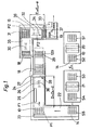
- FIG. 1 schematically shows those processing stations at which method steps according to the invention take place. It is assumed that the coupons have already been printed on both sides in offset printing and also on one side in steel engraving. The last printing process for the note sheets prepared in this way is that the other sheet side is also printed with an engraved image.
- the engraving printing unit 20 provided for this purpose is indicated schematically in FIG. 1.
- the individual, fully printed sheets 10 each have 24 security impressions or so-called individual benefits, which are arranged in a matrix in six rows with four security impressions each.
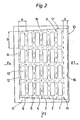
- Fig. 2 such a sheet 10 is shown enlarged with its six rows of bills 1 to 6; the banknotes later cut to format are designated by 12 and the actual banknote impressions surrounded by an unprinted border are designated by 13.
- the individual sheets are pulled by sheet grippers which hold the front sheet edge as they pass through the printing units.
- This sheet edge lying at the front as it passes through the printing units in the transport direction F o is the so-called gripper edge 14 (FIGS. 1 and 2), and the value rows 1 to 6 are parallel to this gripper edge 14, that is to say transversely to the direction of the sheet passing through the printing units, oriented.
- the remaining three sheet edges are labeled 15, 16 and 17.
- the finished printed sheets 10 of the stack S2 are usually subjected to a visual quality control, in which sheets are discarded with misprints, and then by one for numbering the individual uses Input stack S3 is entered into a numbering machine 21 and stored at its output on an output stack S4.
- a sheet stack S5 is first transported in the direction of the arrow along a transport path 22 to the entrance of a cutting path 24 and brought into a defined starting position P1, in which all sheets 10 of the stack are aligned with their gripper edges 14 at a stop 23.
- the gripper edges 14 form the trailing edge of the sheet and thus the reference edge of the sheet stack which is decisive for the strip cut, on which finger-like slides are known an automatic feed device 26 to feed the stacks.
- the edge of the sheet is cut here which forms the rear edge of the strip layers during the later bundle cut, that is, in the example considered, the left side edge 15 of the sheet 10 in the feed direction.
- the strip cutter 27 designed as a cross cutter, the edge is first cut at the front of the stack of the front edge 16 of the sheet 10 (FIG. 2), then the stack is divided step by step into its six strip layers 18, which correspond to the six value rows 1 to 6, and finally the rear edge trim is on the back of the last strip layer the gripper edge 14 executed.
- the waste paper from the edge trimmings falls through a waste flap. When a stack is cut, the following stack is automatically fed.
- a banding station 29 with a number of individual banding devices corresponding to the number of blanks per strip, in the example considered four banding devices that are operated simultaneously in each work step, in such a way that each layer of strips 18 is simultaneously connected to the four note or Benefit positions with a pre-glued band 129 is surrounded.
- the finished banded strip layers 18 are first removed from the banding station 29 in the direction of the arrow in the longitudinal direction of the strip and then moved along the transport path 35, transversely to the longitudinal direction of the strip, by means of a feed device 30 to the entrance of the cutting path 36, on which an automatic bundle cutting unit 33 designed as a cross cutting unit is installed.
- a feed device 30 to the entrance of the cutting path 36, on which an automatic bundle cutting unit 33 designed as a cross cutting unit is installed.
- all six strip layers 18 belonging to one and the same sheet stack S5 are collected in a defined starting position P2, in which the edges trimmed in the longitudinal cutting device 25 are aligned by abutment against a stop which is formed by the slide system 31 of the feed direction 32 .
- the feed device 32 While previously known installations provide a single feed device with a slide which is common to all the strip layers, the feed device 32 according to the invention, as will be explained later, consists of a number of individual feed devices corresponding to the number of strip layers 18 per stack with slides individually moving the strip layers . All six strip layers 18 belonging to a sheet stack, which, as indicated in FIG. 1, are arranged next to each other at a small distance, are then moved together by means of the feed device 32 in the direction of arrow F2 to the bundle cutting device 33, wherein they are guided in grooves. In the bundle cutter 33, the front edge of all the strip layers 18 corresponding to the sheet side edge 17 (FIG.
- the banded bundles 19 cut to format are advanced to a transport path 37 and arrive at further processing stations which are not of interest here, in which bundle packages with consecutively numbered notes of a particular series are formed and these bundle packages are then banded and packaged.
- This further processing is the subject of, for example, the Swiss patent specification CH 577 426 and the American patent specifications US 3939621 and 4,045,944 by the same applicant.
- the originally set, constant feeds D o , a, E o , and b are used.
- the outline 11 of the overall printing image (including the later value edges) shown in FIG. 2 is, of course, exactly rectangular, corresponding to the exact original geometry and arrangement of the engraving pits of the printing plates, and that in FIG. 2 is also rectangular
- Security impressions 13 shown are all undistorted and of the same size and are always centered after the sheet 10 has been cut into security notes 12 with the same format axb along the dashed cut line, always centered with respect to the unprinted value border.
- the printing plates now expand under the action of the contact forces which are exerted by the printing cylinder during each printing process.
- This deformation is particularly strong in the case of an engraving printing plate, since a particularly high pressure must be used in steel engraving printing.
- the lengthening and widening takes place in a non-linear manner, so that the printing surface assumes an approximately trapezoidal shape, the rear printing plate edge as seen in the direction of rotation of the plate cylinder forming the base side of the trapezoid.
- the outline 11 ' which delimits the area of the total printed image of all the security impressions of a sheet 10 and is shown in broken lines in FIG. 2, and each individual security impression are distorted approximately in a trapezoidal shape.
- the total print image in direction F1 is extended by the amount d compared to its original dimension, which was 6a.
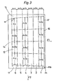
- a sheet 10 the print image of which is distorted and has the outline 11 ', is shown in FIG. 3.
- those lines are drawn in dashed lines in FIG. 3 which would have to form the cut lines in the later strip and bundle cut, so that despite the distortion in all manufactured notes, the security impressions (not shown in FIG. 3) are at least approximately in the mirror, i. H. are centered in relation to the unprinted value border.
- the dimensions of the individual blanks oriented in the direction of F2, that is to say parallel to the gripper edge 14 (that is to say the security impressions including their unprinted border) take along each of the rows of tokens 1 to 6, starting with one compared to the original one Dimension b increased value, first from time to time and then further and from row of banknotes to banknotes, viewed in direction F1, successively larger.
- the individual benefits located at the ends of the value row 6 have a dimension b + y enlarged by the amount y, while the two middle individual benefits are only extended to b + 0.5.
- the two individual uses at the ends have the dimension b + 2y and the two middle ones have the dimension b + y.
- the two individual uses at the ends have the dimension b + 3y and the two middle ones have the dimension b + 1.5y.
- the outer individual uses have the dimensions b + 4y, b + 5y and b + 6y and the middle ones have the dimensions b + 2y, b + 2.5y and b + 3y.
- the values x and y after 100,000 prints can be, for example, approximately 0.05 mm each, so that the extension d of the total printed image of a sheet (FIG. 1) is approximately 1 mm. If the sheet stacks are cut as before with constant feed lengths, i.e. along the dashed lines in FIG. 1, then the printed image 13 of the banknotes 12 is practically still centered within the row of banknotes 6 within the unprinted banknotes border, but all others point Notes have a more or less shifted print image from their central position, whereby these centering errors are greatest for the notes of the value series 1 and of course become stronger and more conspicuous with an increasing number of prints.
- the correction for the strip cut should be considered.
- pressure markings are provided on the engraving printing plate, which define the later cutting lines and inevitably change their position as the printing plate expands.
- these markings are also printed on one side edge 17 of each sheet and, in the example considered (FIGS. 2 and 3), consist of line-shaped markings m which are assigned to the cutting line parallel to the gripper edge 14. These markings are read immediately before the sheet stacks enter the strip cutting unit 27 by a reading device 28 (FIG. 1), which brings the sheet stacks to a standstill in the intended cutting position.
- the distance of the reader 28 from the knife of the strip cutter 27 and the positions of the markings m relative to the cutting lines assigned to them are selected such that after the feed device 26 has been switched off when the reader 28 is activated, a sheet stack arises due to its inertia and the inertia of the Feed mechanism just moved into the desired cutting position and comes to a standstill there.
- This braking distance or run-out distance of a stack is a defined size that can be reproduced exactly for the same stack.
- the following markings m precisely control the sequence of the progressively smaller feed steps, in the example according to FIG. 3 the feed steps a + 6x, a + 5x, etc. to a + x.
- the easy-to-implement markings to be printed and their automatic reading by a reading device 28 controlling the feed device 25 therefore permit constant exact control of the feed lengths when cutting strips as a function of the constantly increasing pressure plate deformation.
- double markings can also be provided, which, as indicated in FIG. 3, consist of two line-shaped markings m s and m located at a short distance from one another.
- the arrangement is then such that when the first mark m s is read, the normal feed speed of the sheet stacks is reduced to a creeping movement and the feed device is only switched off when the second mark m is read.
- the preceding braking of the sheet stacks before they are stopped in this way increases the running accuracy into the cutting position and is expedient when the sheet stacks are pushed forward in the usual way, as described, by means of sliders which only abut the rear edge of the stack.
- this side edge trimming is not always carried out exactly at a right angle to the gripper edge 14 (FIG. 1), but rather along the side boundary 15 Line of the trapezoidal outline 11 'of the overall printed image; this line of intersection includes the angle a with the gripper edge 14 (FIG. 3), which becomes greater than 90 ° with the onset of distortion and increases with increasing pressure plate expansion.
- the longitudinal cutting device 25 or its knife can be rotated about a vertical axis in such a way that the cutting angle tt relative to the gripper edge 14, starting from an originally right angle, can be made ever larger during operation.
- the slides 311 to 316 of the feed devices 321 to 326 are also set more and more obliquely in the course of operation, so that they are always oriented parallel to the rear edge of the strip layers 18 and thus lie snugly against them in order to ensure a well-defined feed.
- the slides 311 to 316 can be pivoted about vertical axes within a sufficient angle.
- this cutting angle ex of the slitter 25 can be controlled automatically.
- the cutting angle is changed as a function of the increasing distortion, as explained, which in the simplest case can be carried out by hand in such a way that after the passage of, for example, 50,000 to 100,000 sheets each, corresponding to 500 to 1000 stacks with 100 sheets each, based on a visual inspection and measurement of the printed images or the stretched printing plate.
- This can be a local pattern, a certain color range or a striking contrast, preferably the contrast between the light, unprinted value border and a dark area of the value print.
- a characteristic point in particular a sufficient contrast at the limit of the printed value of the banknote, can be found practically on all banknotes and can be used as a natural marking selectively recognizable by a reading device, which defines the adjacent cutting line.
- readers with the required selectivity are readily available or are easily adaptable.
- reading windows can be used in a known manner, as is done, for example, when reading register marks in printing machines.
- the characteristic locations to be read for controlling the feeds can also be fluorescence areas provided on the bill of value.
- these characteristic points can also be non-optical properties, for example metal threads or the like embedded in the note paper, to which suitable detectors respond.
- the mark for the feed control during the bundle cut is the contrast between the light value note border lying in the direction of F2 and the dark printed image of each individual use on each of the strip layers 18.
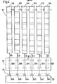
- a reader system 34 with the six readers 341 to 346 (FIG. 4) is installed in front of the bundle cutter 33, which individually scan the individual strip layers 18, corresponding to the six rows of notes 1 to 6, and the feed devices 321 that move these strip layers control up to 326 individually. Starting from the aligned starting position P2, the six strip layers 18 are advanced together, which are of different lengths on their rear edges because of the somewhat oblique edge trim, as illustrated in FIG. 4.
- the reader 341 first responds to the first contrast point of the strip position corresponding to the bank note row 1, that is to say to the front boundary of the first printed security image, and therefore switches off the feed device 321.
- the arrangement is such that the strip position then comes to a standstill after a total feed length E1 in the first desired cutting position, in which the front edge of the strip layer is trimmed.
- the feed lengths of the remaining strip positions which correspond to the value note rows 2 to 6 and which are correspondingly controlled by the readers 342 to 346, increase successively and are designated in FIG. 4 by E2, E3, E4, E5 and E6.
- E E o - e i applies, whereby the index i refers to one of the six value series 1 to 6 and can accordingly assume the values 1 to 6.
- the feed device 321 which measures the sum of the four feed steps covered in the bundle cuts of the strip position ; this sum, 4b + 18y in the example under consideration, corresponds precisely to the required length dimension, from which the cutting angle ⁇ can be derived on the basis of the relationship mentioned.
- the measured value supplied by the measuring device 351 is therefore fed to a suitably programmed mini-computer or microprocessor, which calculates the associated value of the angle, x and issues a control command for correspondingly controlling the cutting position of the longitudinal cutting device 25.
- a suitably programmed mini-computer or microprocessor which calculates the associated value of the angle, x and issues a control command for correspondingly controlling the cutting position of the longitudinal cutting device 25.
- other methods for measuring the respective distortion state of the overall printed image 11 'and for automatically evaluating the measurement results for the purpose of controlling the desired cutting angle are also possible.
- reading devices are dispensed with and the control is carried out with the aid of a mini computer or microprocessor, depending on the feed values covered in each case in the strip cut.
- a mini computer or microprocessor Use is made of the theoretically and / empirically determinable relationship that exists between the elongation in the longitudinal direction and the transverse direction for a given printing plate. If a characteristic strain value in the direction of F1 (FIG. 3) is known, then the corresponding strain in the direction of F2 can be calculated on the basis of this relationship, or at least can be estimated with sufficient accuracy for the present purposes.
- a measuring device 36 which is indicated schematically in FIG.
- This second embodiment requires only a reader 28 for reading the markings defining the strip cuts and for controlling the strip cutting unit 27, as well as a correspondingly programmed mini-computer or microprocessor, to which the measured feed lengths of the feed device 26 are entered as measured values and which controls the described individual feeds for the bundle cut; at the same time, in this case, he preferably also controls the setting of the longitudinal cutting unit 25 to the respective cutting angle a, which also results from the relationship or programming mentioned.
- the measuring device for measuring the feed paths covered can simply consist of a rev counter, which measures the number of revolutions carried out by the stepper motor mentioned.
- a feed path covered by the feed device can also be determined in another way, for example optically by measuring the distance covered by a sheet stack or a strip position.
- a third embodiment of the method it is also possible to dispense with printing markings and readers in such a way that all feeds, both in the case of strip cutting and bundle cutting, are controlled by a computer which has been given a program which detects the increasing elongation of the printing plate in question as a function of Describes the number of prints.
- the course of the expansion of a particular Druckpla t tentyps with the number of prints can be performed mathematically and / or empirically determined or based on experience and establish therefrom a complete program for the feed control.
- the programmable feed devices 26 and 32 are initially set in the usual way to the constant original feed values D o , a, E o and b and are always re-programmed by hand in the course of operation as soon as the centering error that arises becomes noticeable to the naked eye or begins to become disruptive.
- the distortion effects produced by the printing plate stretching in the transverse direction are less disturbing than those in the longitudinal direction (direction F o ), because namely the widening in the transverse direction takes place symmetrically on both sides and therefore the security impressions in the central region of the sheets are only relatively slight after the one and shifted to the other side and the laterally outer security prints experience a shift that only corresponds to approximately half of the overall widening of the overall printed image 11 '.
- the distortion effects add up in the individual value rows 6 to 1 of a sheet in the longitudinal direction, that is to say in the direction F1, as the example according to FIGS. 2 and 3 illustrates. For this reason, it may be sufficient to apply the feedrate correction described only for strip cutting and, as usual, to work with constant feed rates for bundle cutting.
- the correction options described above for the strip cut and for the bundle cut can also be combined in any way, for example in such a way that the feed control takes place fully automatically during the strip cut, while the feed program for the bundle cut is changed by hand as required.
- the accuracy of the centering of the security prints within their border not only depends on the printing plate stretching, but is subject to more or less large tolerances, which essentially depend on differences in the format of the note sheets, on the pressing and stretching of the paper during printing and come from its moisture content and from inaccuracies when cutting. It would therefore be useless to introduce feed corrections that are more precise than the tolerances mentioned, to which the centering of the security notes is subject for other reasons.
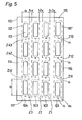
- FIGS. 5 and 6 show a bill of value 110 with 16 individual bills 112, which are arranged in four rows of bills 101 to 104 of four individual bills each. It is assumed that the engraving printing plate, which has printed this sheet, has undergone a noticeable stretching, as in the example according to FIGS. 2 and 3, so that the outline 111 'of the total printed image of all security impressions 113 is again distorted approximately trapezoidally.
- print markings m are provided on the side edge 117, which are read by the reader 28 for feed control during strip cutting, and on the other hand print markings n, which are printed on the intermediate strip between adjacent individual uses of each row of notes and can be read from the readers 341 to 344 (FIG. 6) for the purpose of feed control during the bundle cut of the individual strip layers 118.
- All printing markings m and n define the widths of the front edges and intermediate strips to be cut, which are variable as a result of the printing plate expansion.
- the front edge 116 is first cut off in the strip cutter 27, the feed into this cutting position being controlled by the reading device 28 by reading the first pressure marking m .
- the length a of the following feed step into the cutting position required for the first strip cut is pre-programmed.
- the feed into the following sectional position, in which the intermediate strip Z1 is cut off, is in turn controlled by the reading device 28 by reading the second print mark m. This is followed by a feed step of length a, and so on.
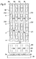
- the feed device 32 for the four strip layers (118) belonging to a stack again comprises feed devices 321 to 324 individually assigned to these strip layers with their slides 311 to 314.
- each of the feed devices 321 to 324 carries out a permanently programmed feed step of length b, whereupon the foremost bundles of notes of each strip layer are cut off.
- the next feed is in turn controlled by the reading devices, individually for each strip position, when reading the respective marking n on the intermediate strips Z11, Z21, Z31 and Z41, whereupon these strip layers are cut off together. This cut is followed by a programmed feed step of length b, etc.
- the described feed control when working with intermediate cuts can also be carried out either according to a prepared program that changes as a function of the printing plate expansion or by hand, as is the case for the example according to FIGS. 2 to 4 has been described.
- feed control by reading devices it is also possible, without special printing markings m and n, to use characteristic points of the individual use that are selectively recognizable by the reading devices as natural markings, in particular the contrast at the boundary of the security print, as explained earlier.
- the method according to the invention can also be applied to sheets of notes in which the strip cuts are made with individual cuts, whereas the bundle cuts are made with intermediate cuts.
- both opposite side edges of the sheet stack can be trimmed simultaneously on the cutting section 24 before the strip cuts are carried out.
- the strip layers belonging to a sheet stack can be divided into bundles of notes one after the other in time, the feed steps being successively changed individually for each strip layer.
Description
Die Erfindung bezieht sich auf ein Verfahren gemäß dem Oberbegriff des Patentanspruchs 1 und auf eine automatische Schneidmaschine zur Durchführung des Verfahrens gemäß DE-A-2757186.The invention relates to a method according to the preamble of
Bei der Fertigung von Wertscheinen, insbesondere von Banknoten, werden im allgemeinen zunächst Wertscheinbogen mit einer bestimmten Anzahl von Nutzen, das heißt mit einer bestimmten Anzahl von matrizenförmig angeordneten Wertscheindrucken, hergestellt und dann diese Bogen stapelweise Schritt für Schritt in Streifenlagen und anschließend die Streifenlagen in Wertscheinbündeln zerschnitten, wobei die Einzelwertscheine der Bündel ihr fertiges Format erhalten. Beim Einsatz automatisch arbeitender Schneidmaschinen werden die Vorschublängen beim schrittweisen Vorschub der Bogenstapel und der Streifenlagen jeweils aufgrund eines einmal eingestellten Vorschubprogramms fest vorgegeben, und zwar in Abhängigkeit von der Wertscheingröße bzw. dem gewünschten Wertscheinformat. Die anfallenden, fertig geschnittenen Wertscheine sind daher natürlich alle gleich groß. Diese einheitliche Wertscheingröße ist für die automatische Weiterverarbeitung, Sortierung und Verpackung der Wertscheinbündel vorteilhaft.When producing notes of value, in particular banknotes, notes of sheet with a certain number of benefits, that is to say with a certain number of security prints arranged in a matrix, are generally produced first and then these sheets are stacked step by step in strip layers and then the strip layers in bundles of notes cut, whereby the individual notes of the bundle receive their finished format. When using automatically working cutting machines, the feed lengths for the step-by-step feed of the sheet stacks and the strip positions are fixed based on a feed program that has been set once, depending on the size of the banknotes or the desired bill format. The accrued, cut vouchers are of course all the same size. This uniform size of notes is advantageous for the automatic further processing, sorting and packaging of the bundles of notes.
Nun ist es jedoch aus ästhetischen Gründen und auch aus Gründen der Fälschungssicherheit wünschenswert, daß das Druckbild eines Wertscheins stets zentriert innerhalb der Wertscheinrändern oder, wie man sagt, stets exakt im Spiegel liegt. Diese Bedingung läßt sich bisher immer dann nicht exakt erfüllen, wenn der Wertscheindruck einen direkten Tiefdruck, insbesondere einen Stahlstichdruck, einschließt, bei welchem die Druckplatten einem sehr hohen Anpreßdruck unterliegen und unter der Wirkung dieser Kräfte im Laufe des Betriebs eine allmähliche Dehnung erfahren, das heißt zunehmend länger und auch breiter werden, wobei diese Verbreiterung längs der Druckplatte in zum Drehsinn des Plattenzylinders entgegengesetzter Richtung größer wird. Die schematische Gestalt einer derart verformten, etwa trapezförmigen Druckplatte entspricht dem Umriß 11' in der später noch näher erläuterten Fig. 2. Entsprechend der Verlängerung und Verbreiterung der Druckplatte ändern sich Größe und Positionen der Aufdrucke, so daß beim automatischen Schneiden der Bogenstapel mit konstanten Vorschublängen fertig geschnittene Wertscheine anfallen, bei denen mit zunehmender Zahl der Drucke das Druckbild immer mehr aus seiner zentrierten Lage verschoben und daher der Unterschied in den Breiten der Ränder immer auffallenderwird.Now, for aesthetic reasons and also for reasons of security against forgery, it is desirable that the printed image of a note is always centered within the edges of the note or, as is said, always exactly in the mirror. This condition has so far not always been met exactly if the security print includes direct gravure printing, in particular a steel engraving print, in which the printing plates are subjected to a very high contact pressure and undergo a gradual expansion under the action of these forces during operation, that is to say become increasingly longer and also wider, this widening becoming larger along the pressure plate in the direction opposite to the direction of rotation of the plate cylinder. The schematic shape of such a deformed, approximately trapezoidal printing plate corresponds to the outline 11 'in FIG. 2, which will be explained in more detail later. In accordance with the lengthening and widening of the printing plate, the size and positions of the prints change, so that the sheet stacks are cut automatically with constant feed lengths Completely cut notes of value are created, in which the printed image moves more and more out of its centered position with increasing number of prints and therefore the difference in the widths of the margins becomes more and more striking.
Der Erfindung liegt die Aufgabe zugrunde, ein Verfahren zu schaffen, welches es trotz einer im Laufe des Betriebs auftretenden Druckplattenverformung ermöglicht, beim Zerschneiden der Bogenstapel stets Wertscheine zu erhalten, die in bezug auf die Wertscheinrändern wenigstens näherungsweise zentrierte Druckbilder haben.The invention has for its object to provide a method which, despite a printing plate deformation occurring in the course of operation, always allows you to obtain coupons when the sheet stacks are cut, which have at least approximately centered printed images with respect to the edges of the coupons.
Diese Aufgabe wird erfindungsgemäß durch die im kennzeichnenden Teil des Patentanspruchs 1 sowie, hinsichtlich der Schneidmaschine zur Durchführung des erfindungsgemäßen Verfahrens, durch die im Patentanspruch 14 angegebenen Merkmale gelöst.This object is achieved according to the invention in the characterizing part of
Die Änderung der Vorschublängen kann im einfachsten Falle von Hand aufgrund eines Erfahrungsprogramms durchgeführt werden, das für die betreffenden Druckplatten empirisch und gegebenenfalls auch theoretisch aufgestellt wurde. Man beginnt dann mit der Neueinstellung der Vorschublängen, sobald die Druckplattenverformung ein in der Praxis störendes Ausmaß annimmt, was beispielsweise nach 50000-100 000 Drucken der Fall sein kann. Nach jeweils weiteren 50000-100000 Drucken können dann die Längen der Vorschubbewegungen erneut entsprechend geändert und angepaßt werden. Die vorzunehmenden Neueinstellungen des ursprünglichen Vorschub-Programms können auch aufgrund einer regelmäßigen Inspektion und Ausmessung der Druckplatte nach zum Beispiel je 50 000 oder 100 000 Drucken erfolgen.In the simplest case, the change in the feed lengths can be carried out manually on the basis of an experience program which has been set up empirically and possibly also theoretically for the printing plates in question. One then begins to readjust the feed lengths as soon as the deformation of the printing plate takes on a dimension which is disturbing in practice, which can be the case, for example, after 50,000-100,000 prints. After each additional 50000-100000 prints, the lengths of the feed movements can be changed and adjusted accordingly. The readjustments to be made to the original feed program can also be carried out on the basis of a regular inspection and measurement of the printing plate, for example after every 50,000 or 100,000 prints.
Es ist auch möglich, die Vorschublängen automatisch durch einen Rechner aufgrund eines für jeden Druckplattentyp vorbereiteten Programms zu steuern, welches mit zunehmender Zahl der Drucke variiert.It is also possible to control the feed lengths automatically by means of a computer on the basis of a program prepared for each type of printing plate, which varies with an increasing number of prints.
Eine Längenänderung der einzelnen Vorschübe läßt sich mit handelsüblichen Vorschubeinrichtungen, die unter dem Namen Linearverstärker bekannt sind, besonders genau und einfach durchführen. Diese Linearverstärker haben ein hydraulisches Zylinder-Kolben-System, wobei die dosierte Druckmittelspeisung des hydraulischen Zylinders mit Hilfe eines Schrittmotors erfolgt, der bei jeder Umdrehung das Druckmittel-Einlaßventil kurzzeitig öffnet; dadurch wird bei einer Umdrehung des Schrittmotors eine genau dosierte, kleine Druckmittelmenge derart dem Zylinder zugeführt, daß der Kolben einen Vorschub von beispielsweise 0,1 mm ausführt. Ein derartiger hydraulisch gesteuerter Vorschub arbeitet auch mit hinreichend geringer Ansprechzeit.A change in length of the individual feeds can be carried out particularly precisely and easily with commercially available feed devices, which are known under the name linear amplifier. These linear amplifiers have a hydraulic cylinder-piston system, the metered pressure medium supply to the hydraulic cylinder being carried out with the aid of a stepper motor which briefly opens the pressure medium inlet valve with each revolution; as a result, a precisely metered, small amount of pressure medium is supplied to the cylinder during one revolution of the stepping motor in such a way that the piston carries out a feed of, for example, 0.1 mm. Such a hydraulically controlled feed also works with a sufficiently short response time.
Eine bevorzugte Durchführungsform des Verfahrens nach der Erfindung besteht darin, auf der Druckplatte Druckmarkierungen anzubringen, welche die späteren Schnittlinien definieren und zwangsläufig die Verformungen der Druckplatte mitmachen, und die Vorschubeinrichtungen durch Lesegeräte zu steuern, welche die beim Druckvorgang aufgebrachten Markierungen ablesen. Diese Markierungen werden auf die Ränder der Bogen und gegebenenfalls auf die zwischen den Druckbildern liegenden Bereiche aufgedruckt, welche beim späteren Bogenrandbeschnitt bzw. bei späteren Zwischenschnitten als Abfallstreifen abgeschnitten werden. Auf diese Weise läßt sich die Schneidmaschine als Funktion der Positionen dieser Druckmarkierungen automatisch so steuern, daß stets Wertscheine geschnitten werden, deren Druckbild korrekt oder zumindest wesentlich genauer als bisher zentriert ist.A preferred embodiment of the method according to the invention is to apply printing marks on the printing plate, which define the later cutting lines and inevitably take part in the deformations of the printing plate, and to control the feed devices by reading devices which read the markings made during the printing process. These markings are printed on the edges of the sheets and, if appropriate, on the areas lying between the printed images, which are cut off as waste strips during later sheet edge trimming or later intermediate cuts. In this way, the cutting dimension Automatically control the machine as a function of the positions of these print markings so that banknotes are always cut whose print image is centered correctly or at least much more precisely than before.
Die Änderung der Vorschublängen beim Schneiden hat natürlich, wenn man auf Zwischenschnitte verzichtet, zur Folge, daß die fertig geschnittenen Wertscheine, abhängig von der Druckplattenverformung, in ihrer Größe leicht variieren. Jedoch ist der erzielte Vorteil, daß nämlich das Druckbild der Wertscheine stets wenigstens näherungsweise exakt im Spiegel liegt, wesentlich höher zu bewerten als die etwas unterschiedliche Größe der anfallenden Wertscheine. Diese wechselnde Größe nämlich ist in der Praxis überhaupt nicht bemerkbar und könnte allenfalls durch exakte Vermessungen mehrerer Wertscheine festgestellt werden; auch fällt die leicht unterschiedliche Größe der Wertscheine bei deren Weiterverarbeitung zu verpackten Bündelpaketen praktisch nicht ins Gewicht. Dagegen fällt ein nicht korrekt zentriertes Druckbild dem Betrachter eines Wertscheins sofort auf.The change in the feed lengths when cutting naturally means that, if one does not make intermediate cuts, the finished cut notes of value vary slightly in size, depending on the deformation of the printing plates. However, the advantage achieved, namely that the printed image of the notes of value is always at least approximately exactly in the mirror, is to be rated much higher than the somewhat different size of the notes of value obtained. This changing size is in fact not noticeable in practice and could at best be determined by exact measurements of several notes of value; the slightly different size of the banknotes is practically negligible when it is processed into packaged bundle packages. In contrast, an incorrectly centered printed image immediately notices the viewer of a note.
Wenn jedoch darauf Wert gelegt wird, daß alle Wertscheine das gleiche konstante Format aufweisen sollen, dann kann selbstverständlich mit Zwischenschnitten gearbeitet werden, was ein etwas aufwendigeres Verfahren darstellt; in diesem Falle müssen die Abfallstreifen im allgemeinen wenigstens etwa 2 mm breit sein, damit einwandfreie Schnitte ausführbar sind.However, if it is important that all notes of value should have the same constant format, it is of course possible to work with intermediate cuts, which is a somewhat more complex process; in this case the waste strips must generally be at least about 2 mm wide so that perfect cuts can be made.
Im allgemeinen fällt der Verformungseffekt der Grundplatte in Längsrichtung stärker ins Gewicht als in Querrichtung, so daß unter Umständen die Vorschublängen nur bei den parallel zum Greiferrand erfolgenden Streifenschnitten geändert zu werden brauchen und bei den Bändelschnitten auf eine Zentrierungskorrektur verzichtet werden kann. Es ist jedoch auch denkbar, daß in bestimmten Fällen nur eine Zentrierungskorrektur bei den Bündelschnitten vorgenommen und bei den Streifenschnitten mit fest vorgegebenen Vorschublängen gearbeitet wird.In general, the deformation effect of the base plate is more important in the longitudinal direction than in the transverse direction, so that under certain circumstances the feed lengths only need to be changed for the strip cuts made parallel to the gripper edge and centering correction can be dispensed with for the ribbon cuts. However, it is also conceivable that, in certain cases, only a centering correction is made for the bundle cuts and the strip cuts are made with fixed feed lengths.
Zweckmäßige weitere Ausgestaltungen der Erfindung sind in den abhängigen Patentansprüchen angegeben.Advantageous further refinements of the invention are specified in the dependent claims.
Die Erfindung wird anhand der Zeichnungen näher erläutert. Es zeigt
- Fig. 1 die schematische Ansicht der wesentlichen Verarbeitungsstationen bei der Fertigung von Wertscheinen gemäß der vorliegenden Erfindung,
- Fig. 2 die schematische Ansicht eines mit einer neuen, unverformten Druckplatte bedruckten Wertscheinbogens, welcher 6 x 4 = 24 Wertscheindrucke bzw. Einzelnutzen aufweist und auf welchem die späteren Schnittlinien gestrichelt dargestellt sind; strichpunktiert ist der etwa trapezförmige Umriß des verzerrten Gesamtdruckbildes aller Wertscheindrucke veranschaulicht, wie es eine nach zahlreichen Drucken entsprechend gedehnte Druckplatte erzeugt, wobei die Verzerrung, ebenso wie in den folgenden Figuren, aus Gründen der Anschaulichkeit übertrieben und nicht maßstabsgerecht dargestellt ist,
- Fig. 3 den Bogen nach Fig. 2 mit dem verzerrten Gesamtdruckbild und den strichpunktiert angedeuteten, späteren Schnittlinien, deren Lagen aufgrund der Änderungen der Vorschublängen korrigiert sind,
- Fig. 4 den das Bündelschneidwerk nach Fig. 1 einschließenden Bereich mit den sechs Streifenlagen in schematischer, vergrößerter Darstellung mit den zugeordneten Vorschubeinrichtungen,
- Fig. 5 einen 4 x 4 = 16 Wertscheindrucke aufweisenden Bogen mit verzerrtem Druckbild, der unter Verwendung von Zwischenschnitten verarbeitet wird und auf dem die späteren Schnittlinien gestrichelt angedeutet sind, und
- Fig. 6 eine der Fig. 4 entsprechende Darstellung, welche den Vorschub der vier Streifenlagen des Bogens nach Fig. 5 beim Bündelschnitt veranschaulicht.
- 1 is a schematic view of the essential processing stations in the manufacture of notes of value according to the present invention,
- FIG. 2 shows the schematic view of a note sheet printed with a new, undeformed printing plate, which has 6 × 4 = 24 note impressions or single use and on which the later cut lines are shown in broken lines; Dash-dotted lines illustrate the roughly trapezoidal outline of the distorted overall printed image of all security impressions, as is produced by a printing plate which has been stretched accordingly after numerous prints, the distortion, as in the following figures, being exaggerated for reasons of clarity and not to scale,
- 3 the sheet according to FIG. 2 with the distorted overall printed image and the later cut lines indicated by dash-dotted lines, the positions of which have been corrected due to the changes in the feed lengths,
- 4 the area including the bundle cutting unit according to FIG. 1 with the six strip layers in a schematic, enlarged illustration with the assigned feed devices, FIG.
- 5 shows a sheet having 4 x 4 = 16 security impressions with a distorted printed image, which is processed using intermediate cuts and on which the later cut lines are indicated by dashed lines, and
- FIG. 6 shows a representation corresponding to FIG. 4, which illustrates the advance of the four strip layers of the sheet according to FIG. 5 in a bundle cut.
Fig. 1 zeigt schematisch diejenigen Verarbeitungsstationen, an denen Verfahrensschritte nach der Erfindung stattfinden. Es wird angenommen, daß die Wertscheinbogen bereits beidseitig im Offsetdruck und außerdem auf der einen Seite im Stahlstichdruck bedruckt worden sind. Der letzte Druckvorgang für die so vorbereiteten Wertscheinbogen besteht darin, daß auch noch die andere Bogenseite mit einem Stichdruckbild bedruckt wird. Das dafür vorgesehene Stichdruckwerk 20 ist schematisch in Fig. 1 angedeutet. Die Wertscheinbogen, die am Eingang des Stichdruckwerks 20 in Form eines Eingangsstapels S1 bereitliegen, durchlaufen in bekannter Weise einzeln nacheinander das Stichdruckwerk 20 und werden an dessem Ausgang auf einem Ausgangsstapel S2 gesammelt. Wie angedeutet, haben die einzelnen, fertig bedruckten Bogen 10 je 24 Wertscheindrucke bzw. sogenannte Einzelnutzen, die matrizenförmig in sechs Reihen mit je vier Wertscheindrucken angeordnet sind. In Fig. 2 ist vergrößert ein derartiger Bogen 10 mit seinen sechs Wertscheinreihen 1 bis 6 dargestellt; die später auf Format geschnittenen Wertscheine sind mit 12 und die von einen unbedruckten Rand umgebenen eigentlichen Wertscheindrucke mit 13 bezeichnet.1 schematically shows those processing stations at which method steps according to the invention take place. It is assumed that the coupons have already been printed on both sides in offset printing and also on one side in steel engraving. The last printing process for the note sheets prepared in this way is that the other sheet side is also printed with an engraved image. The
Bekanntlich werden die einzelnen Bogen beim Durchlaufen der Druckwerke von Bogengreifern gezogen, die den vorderen Bogenrand halten. Dieser beim Durchlaufen der Druckwerke in Transportrichtung Fo vorn liegende Bogenrand ist der sogenannte Greiferrand 14 (Fig. 1 und 2), und die Wertscheinreihen 1 bis 6 sind parallel zu diesem Greiferrand 14, also quer zur Richtung des Durchlaufs der Bogen durch die Druckwerke, orientiert. Die übrigen drei Bogenränder sind mit 15,16 und 17 bezeichnet.As is known, the individual sheets are pulled by sheet grippers which hold the front sheet edge as they pass through the printing units. This sheet edge lying at the front as it passes through the printing units in the transport direction F o is the so-called gripper edge 14 (FIGS. 1 and 2), and the
Die fertig bedruckten Bogen 10 des Stapels S2 werden gewöhnlich einer visuellen Qualitätskontrolle unterworfen, bei welcher Bogen mit Fehldrucken ausgesondert werden, und danach zwecks Numerierung der Einzelnutzen von einem Eingangsstapel S3 in eine Numeriermaschine 21 eingegeben und an deren Ausgang auf einem Ausgangsstapel S4 abgelegt.The finished printed
Anschließend werden die numerierten Bogen stapelweise nacheinander einer automatischen Schneidmaschine zugeführt. Dazu wird nach Fig. 1 ein Bogenstapel S5 zunächst in Richtung des Pfeils längs einer Transportstrecke 22 zum Eingang einer Schneidstrecke 24 transportiert und in eine definierte Anfangsposition P1 gebracht, in welcher alle Bogen 10 des Stapels mit ihren Greiferrändern 14 an einem Anschlag 23 ausgerichtet sind. Beim folgenden Transport des Stapels längs der Schneidstrecke 24 in Richtung des Pfeils F1 zum Streifenschneidwerk 27 und während des schrittweisen Vorschubs innerhalb dieses Streifenschneidwerks 27 bilden die Greiferränder 14 die Bogenhinterkanten und damit die für den Streifenschnitt maßgebende Bezugskante des Bogenstapels, an welcher in bekannter Weise fingerartige Schieber einer automatischen Vorschubvorrichtung 26 anliegen, um die Stapel vorzuschieben.The numbered sheets are then fed one after the other to an automatic cutting machine. 1, a sheet stack S5 is first transported in the direction of the arrow along a
An der Schneidstrecke 24 befindet sich vor dem Streifenschneidwerk 27 seitlich ein Längsschneidwerk 25, an dem die Stapel gestoppt werden und in welchem ein Seitenrandbeschnitt stattfindet. Es wird hier derjenige Bogenrand beschnitten, welcher beim späteren Bündelschnitt den rückwärtigen Rand der Streifenlagen bildet, das ist im betrachteten Beispiel der in Vorschubrichtung linke Seitenrand 15 der Bogen 10. Danach erfolgt in dem als Querschneidwerk ausgebildeten Streifenschneidwerk 27 zunächst an der Vorderseite des Stapels der Randbeschnitt des vorderen Randes 16 der Bogen 10 (Fig. 2), dann wird der Stapel schrittweise durch je einen Schnitt in seine sechs Streifenlagen 18 zerteilt, welche den sechs Wertscheinreihen 1 bis 6 entsprechen, und schließlich wird auf der Rückseite der letzten Streifenlage der hintere Randbeschnitt des Greiferrandes 14 ausgeführt. Der Papierabfall bei den Randbeschnitten fällt durch eine Abfallklappe. Wenn ein Stapel zerteilt ist, wird automatisch der folgende Stapel zugeführt.On the
Hinter dem Streifenschneidwerk 27 befindet sich eine Banderolierstation 29 mit einer der Nutzenzahl je Streifen entsprechenden Anzahl von einzelnen Banderoliereinrichtungen, im betrachteten Beispiel also vier Banderoliereinrichtungen, die bei jedem Arbeitsgang gleichzeitig betrieben werden, derart, daß jede Streifenlage 18 gleichzeitig an den vier Wertschein- bzw. Nutzenpositionen mit je einer vorgeleimten Banderole 129 umgeben wird.Behind the
Die fertig banderolierten Streifenlagen 18 werden zunächst im Sinne des Pfeils in Streifenlängsrichtung von der Banderolierstation 29 entfernt und dann längs der Transportstrecke 35, quer zur Streifenlängsrichtung, mittels einer Vorschubvorrichtung 30 zum Eingang der Schneidstrecke 36 bewegt, auf der ein als Querschneidwerk ausgebildetes, automatisches Bündelschneidwerk 33 installiert ist. Am Eingang dieser Schneidstrecke 36 werden jeweils alle zu ein und demselben Bogenstapel S5 gehörenden sechs Streifenlagen 18 in einer definierten Anfangsposition P2 gesammelt, in welcher die im Längsschneidwerk 25 beschnittenen Kanten durch Anlage an einem Anschlag ausgerichtet sind, welcher vom Schiebersystem 31 der Vorschubrichtung 32 gebildet wird. Während in bisher bekannten Installationen eine einzige, allen Streifenlagen gemeinsame Vorschubvorrichtung mit einem Schieber vorgesehen ist, besteht die Vorschubvorrichtung 32 gemäß der Erfindung, wie später noch erläutert, aus einer der Zahl der Streifenlagen 18 je Stapel entsprechenden Anzahl einzelner Vorschubeinrichtungen mit die Streifenlagen individuell bewegenden Schiebern. Alle zu einem Bogenstapel gehörenden sechs Streifenlagen 18, die, wie in Fig. 1 angedeutet, mit geringem Abstand nebeneinander angeordnet sind, werden dann mittels der Vorschubvorrichtung 32 im Sinne des Pfeils F2 gemeinsam zum Bündelschneidwerk 33 bewegt, wobei sie in Nuten geführt werden. Im Bündelschneidwerk 33 wird zunächst der dem Bogenseitenrand 17 (Fig. 2) entsprechende Vorderrand aller Streifenlagen 18 beschnitten und dann werden schrittweise alle sechs Streifenlagen 18 gleichzeitig durch drei aufeinanderfolge Schnitte in einzelne Wertscheinbündel 19 zerschnitten, die bereits banderoliert sind und in denen die Wertscheine ihr fertiges Format haben. Bei diesen Vorschüben bilden die beschnittenen rückwärtigen Kanten die für den Bündelschnitt maßgebenden Bezugskanten, an denen die Schieber der Vorschubvorrichtung 32 anliegen.The finished banded
Die vorstehend erläuterte Verarbeitung von Wertscheinbogen zu banderolierten Wertscheinbündeln sowie die dazu verwendeten Schneid- und Banderoliermaschinen sind bekannt und beispielsweise in der schweizerischen Patentschrift CH 612 639 bzw. der amerikanischen Patentschrift US 4 283 902 der gleichen Anmelderin beschrieben, ebenso auch in der älteren deutschen Patentanmeldung DE-A-3 238 994 (veröffentlicht am 5. 5. 83) der gleichen Anmelderin.The processing of note sheets into banded note bundles as well as the cutting and banding machines used for this purpose are known and are described, for example, in Swiss Patent CH 612 639 and US Patent No. 4,283,902 by the same applicant, as well as in the older German patent application DE -A-3 238 994 (published May 5, 83) by the same applicant.
Die auf Format geschnittenen banderolierten Bündel 19 werden auf eine Transportstrecke 37 vorgeschoben und gelangen zu weiteren, hier nicht interessierenden Verarbeitungsstationen, in denen Bündelpakete mit fortlaufend numerierten Wertscheinen einer bestimmten Serie gebildet und dann diese Bündelpakete banderoliert und verpackt werden. Diese weitere Verarbeitung ist beispielsweise Gegenstand der schweizerischen Patentschrift CH 577 426 bzw. der amerikanischen Patentschriften US 3939621 und 4 045 944 der gleichen Anmelderin.The banded bundles 19 cut to format are advanced to a
Außer der Verwendung individueller Vorschubeinrichtungen zum Vorschub der einzelnen Streifenlagen besteht bei der hier anhand der Fig. 1 beschriebenen Schneidmaschine ein weiterer Unterschied zum bekannten Stand der Technik darin, daß aus später noch erläuterten Gründen nur ein Längsschneidwerk 25 zum Randbeschnitt der einen Seitenränder der Bogen vorgesehen ist und der Randbeschnitt auf den gegenüberliegenden Seiten erst im Bündelschneidwerk erfolgt, während es bekannt und üblich ist, anstelle eines Längsschneidwerkes vor dem Streifenschneidwerk 27 zwei gegenüberliegende Längsschneidwerke vorzusehen, welche jeden Stapel gleichzeitig an beiden gegenüberliegenden Seitenrändern auf Format beschneiden.In addition to the use of individual feed devices for feeding the individual strip layers, in the cutting machine described here with reference to FIG. 1, there is a further difference from the known prior art in that, for reasons which will be explained later, only one
Bisher sind nun alle Vorschublängen bzw. Vorschubschritte, welche beim Streifenschnitt und beim Bündelschnitt die exakten Schnittlinien bestimmen, für den jeweils bearbeiteten Bogentyp ein für allemal fest vorgegeben und werden vor Beginn der Bearbeitungsoperationen in Abhängigkeit vom gegebenen Bogen- und Wertscheinformat und der Nutzenzahl fest an den automatischen Vorschubeinrichtungen eingestellt, welche zu diesem Zwecke elektronisch programmierbar sind. Zu diesen fest eingestellten Werten gehören:
- - der Abstand D = Do zwischen der Anfangsposition P1 eines Stapels und derjenigen Stapelposition
im Streifenschneidwerk 27, in welcher der Vorderrandbeschnitt erfolgt; - - die zwischen aufeinanderfolgenden Streifenschnitten erfolgenden Vorschubschritte, welche gleich der Breite a eines Wertscheins 12 sind;
- - der Abstand E = Eo zwischen der Anfangsposition P2 der Streifenlagen 18 und deren
Position im Bündelschneidwerk 37, in welcher der erwähnte Randbeschnitt der Vorderränder der Streifenlagen stattfindet und - - die zwischen aufeinanderfolgenden Bündelschnitten erfolgenden Vorschubschritte, welche jeweils die Länge b eines
Wertscheins 12 haben.
- the distance D = D o between the starting position P1 of a stack and that stack position in the
strip cutting unit 27 in which the front edge trimming takes place; - the feed steps taking place between successive strip cuts, which are equal to the width a of a
note 12; - - The distance E = Eo between the initial position P2 of the strip layers 18 and their position in the
bundle cutter 37, in which the mentioned edge trimming of the front edges of the strip layers takes place and - - The feed steps taking place between successive bundle cuts, each of which has the length b of a
note 12.
Gemäß den in Fig. 1 angegebenen Definitionen D = Do - d und E = Eo - e haben also die erwähnten Abstände, solange die später diskutierten Korrekturen d und e null sind oder nicht berücksichtigt werden, die festen Werte D = Do und E = Eo.According to the definitions D = Do - d and E = Eo - e given in FIG. 1, the specified distances have the fixed values D = D o and E = as long as the corrections d and e discussed later are zero or are not taken into account Eo.
Auch gemäß der vorliegenden Erfindung wird, solange die verwendeten Stichdruckplatten neu sind und keine ins Gewicht fallende Dehnung erfahren haben, mit den ursprünglich eingestellten, konstanten Vorschüben Do, a, Eo, und b gearbeitet. Solange keine merkliche Dehnung der Stichdruckplatten auftritt, ist natürlich der in Fig. 2 angegebene Umriß 11 des Gesamtdruckbildes (einschließlich der späteren Wertscheinränder), entsprechend der exakten ursprünglichen Geometrie und Anordnung der Stichgruben der Druckplatten, genau rechteckförmig, und die in Fig. 2 ebenfalls rechteckig dargestellten Wertscheindrucke 13 sind alle unverzerrt und gleich groß und liegen, nachdem der Bogen 10 längs der gestrichelt eingezeichneten Schnittlinie in Wertscheine 12 mit stets dem gleichen Format a x b zerschnitten worden sind, immer zentriert im Bezug auf die unbedruckte Wertscheinumrandung.According to the present invention, as long as the engraving printing plates used are new and have not undergone any significant expansion, the originally set, constant feeds D o , a, E o , and b are used. As long as there is no noticeable stretching of the engraving printing plates, the
Im Laufe des Betriebes dehnen sich nun die Druckplatten unter der Wirkung der Anpreßkräfte, die bei jedem Druckvorgang durch den Druckzylinder ausgeübt werden. Diese Verformung ist im Falle einer Stichdruckplatte besonders stark, da beim Stahlstichdruck mit einer besonders hohen Anpressung gearbeitet werden muß. Bei dieser Druckplattenverformung erfolgt die Verlängerung und Verbreiterung in nicht linearer Weise, so daß die Druckfläche eine ungefähr trapezförmige Gestalt annimmt, wobei die in Drehrichtung des Plattenzylinders gesehen hintere Druckplattenkante die Basisseite des Trapezes bildet. Dementsprechend werden der Umriß 11', der die Fläche des Gesamtdruckbildes aller Wertscheindrucke eines Bogens 10 begrenzt und in Fig. 2 strichpunktiert dargestellt ist, sowie jeder einzelne Wertscheindruck ungefähr trapezförmig verzerrt.In the course of operation, the printing plates now expand under the action of the contact forces which are exerted by the printing cylinder during each printing process. This deformation is particularly strong in the case of an engraving printing plate, since a particularly high pressure must be used in steel engraving printing. With this printing plate deformation, the lengthening and widening takes place in a non-linear manner, so that the printing surface assumes an approximately trapezoidal shape, the rear printing plate edge as seen in the direction of rotation of the plate cylinder forming the base side of the trapezoid. Accordingly, the outline 11 ', which delimits the area of the total printed image of all the security impressions of a
Im Beispiel nach Fig. 2 ist das Gesamtdruckbild in Richtung F1 gegenüber seiner ursprünglichen Abmessung, die 6a betrug, um den Betrag d verlängert.In the example according to FIG. 2, the total print image in direction F1 is extended by the amount d compared to its original dimension, which was 6a.
Ein Bogen 10, dessen Druckbild derart verzerrt ist und den Umriß 11' hat, ist in Fig. 3 dargestellt. Darüber hinaus sind in Fig. 3 gestrichelt diejenigen Linien eingezeichnet, welche beim späteren Streifen- und Bündelschnitt die Schnittlinien bilden müßten, damit trotz der Verzerrung bei allen hergestellten Wertscheinen die (in Fig. 3 nicht dargestellten) Wertscheindrucke wenigstens näherungsweise im Spiegel liegen, d. h. also in bezug auf die unbedruckte Wertscheinumrandung zentriert sind.A
Die nachstehend beschriebene Vorschubsteuerung mit variierenden Vorschublängen gemäß der Erfindung ermöglicht es nun, jeden Bogen längs dieser »Soll-Schnittlinien« zu zerschneiden, die also die korrigierten Abmessungen der Wertscheine definieren.The feed control described below with varying feed lengths according to the invention now makes it possible to cut each sheet along these “target cutting lines”, which thus define the corrected dimensions of the notes of value.
Im Beispiel nach Fig. 3 ist ein Dehnungszustand der Druckplatte angenommen, bei dem die Abmessungen der einzelnen Wertscheinreihen 6 bis 1 in Richtung F1 sukzessive zunehmen. So hat sich die Breite der dem Greiferrand 14 benachbarten Wertscheinreihe 6 vom ursprünglichen Wert a um einen Betrag x auf den Wert a + x, die der Wertscheinreihe 5 auf den Wert a + 2x und die der folgenden Wertscheinreihen 4 bis 1 auf die Werte a + 3x, a + 4x, a + 5x und a + 6x vergrößert. Die Gesamtverlängerung in Richtung F1 beträgt also 21x, was gleich dem in Fig. 2 angegebenen Betrag d ist. Natürlich braucht es sich in der Praxis bei diesen Verlängerungen nicht gerade um ganzzahlige Vielfache des Zuwachses x der am wenigsten verzerrten Wertscheinreihe 6 zu handeln, wie es hier der Einfachheit halber als Beispiel angenommen wurde.In the example according to FIG. 3, an expansion state of the printing plate is assumed, in which the dimensions of the individual rows of
Die in Richtung F2, also parallel zum Greiferrand 14, orientierten Abmessungen der Einzelnutzen (also der Wertscheindrucke einschließlich ihrer unbedruckten Umrandung) nehmen längs jeder der Wertscheinreihen 1 bis 6, beginnend mit einem gegenüber der ursprünglichen Abmessung b vergrößerten Wert, zunächst ab und dann wieder zu und werden ferner von Wertscheinreihe zu Wertscheinreihe, betrachtet in Richtung F1, sukzessive größer. Im betrachteten Beispiel haben die an den Enden der Wertscheinreihe 6 liegenden Einzelnutzen eine um den Betrag y vergrößerte Abmessung b + y, während die beiden mittleren Einzelnutzen nur auf b + 0,5 gestreckt sind. In der Wertscheinreihe 5 haben die beiden an den Enden liegenden Einzelnutzen die Abmessung b + 2y und die beiden mittleren die Abmessung b + y. In der Wertscheinreihe 4 haben die beiden an den Enden liegenden Einzelnutzen die Abmessung b + 3y und die beiden mittleren die Abmessung b + 1,5y. In den folgenden Wertscheinreihen 3, 2 bzw. 1 haben entsprechend die äußeren Einzelnutzen die Abmessungen b + 4y, b + 5y bzw. b + 6y und die mittleren die Abmessungen b + 2y, b + 2,5y bzw. b + 3y.The dimensions of the individual blanks oriented in the direction of F2, that is to say parallel to the gripper edge 14 (that is to say the security impressions including their unprinted border) take along each of the rows of
Bei einer Bogengröße von beispielsweise 500 x 750 mm können die Werte x und y nach 100000 Drucken zum Beispiel je ungefähr 0,05 mm betragen, so daß die Verlängerung d des Gesamtdruckbildes eines Bogens (Fig.1) etwa 1 mm ausmacht. Wenn die Zerschneidung der Bogenstapel wie bisher mit konstanten Vorschublängen, also längs der in Fig. 1 gestrichelten Linien, erfolgt, dann liegt zwar das Druckbild 13 der Wertscheine 12 im mittleren Bereich der Wertscheinreihe 6 praktisch noch zentriert innerhalb der unbedruckten Wertscheinumrandung, dagegen weisen alle anderen Wertscheine ein mehr oder weniger aus seiner zentralen Lage verschobenes Druckbild auf, wobei diese Zentrierungsfehler für die Wertscheine der Wertscheinreihe 1 am größten sind und natürlich mit zunehmender Anzahl der Drucke immer stärker und auffälliger werden.With a sheet size of 500 x 750 mm, for example, the values x and y after 100,000 prints can be, for example, approximately 0.05 mm each, so that the extension d of the total printed image of a sheet (FIG. 1) is approximately 1 mm. If the sheet stacks are cut as before with constant feed lengths, i.e. along the dashed lines in FIG. 1, then the printed
Um diese Zentrierungsfehler zu vermeiden, werden nun die einzelnen Vorschublängen sowohl beim Streifenschnitt in Richtung F1 als auch beim Bündelschnitt in Richtung F2 entsprechend den vorstehend diskutierten Verzerrungswerten geändert.In order to avoid these centering errors, the individual feed lengths are now changed in accordance with the distortion values discussed above, both in the case of a strip cut in the direction of F1 and in the case of a bundle cut in the direction of F2.
Zunächst soll die Korrektur beim Streifenschnitt betrachtet werden. Um eine vollautomatische Steuerung des beim Streifenschnitt variierenden Vorschubs zu realisieren, werden gemäß einer ersten bevorzugten Durchführungsform des Verfahrens nach der Erfindung auf der Stichdruckplatte Druckmarkierungen vorgesehen, welche die späteren Schnittlinien definieren und zwangsläufig mit fortschreitender Dehnung der Druckplatte ihre Position ändern. Diese Markierungen werden beim Druck der Bogen 10 im Stichdruckwerk 20 mit auf den einen Seitenrand 17 jedes Bogens aufgedruckt und bestehen im betrachteten Beispiel (Fig. 2 und 3) aus strichförmigen Markierungen m, die den zum Greiferrand 14 parallelen Schnittlinie zugeordnet sind. Diese Markierungen werden unmittelbar vor dem Einlauf der Bogenstapel in das Streifenschneidwerk 27 von einem Lesegerät 28 (Fig. 1) abgelesen, welches die Stillsetzung der Bogenstapel in der vorgesehenen Schnittstellung bewirkt.First, the correction for the strip cut should be considered. In order to realize a fully automatic control of the feed varying during strip cutting, according to a first preferred embodiment of the method according to the invention, pressure markings are provided on the engraving printing plate, which define the later cutting lines and inevitably change their position as the printing plate expands. When the
Der Abstand des Lesegeräts 28 vom Messer des Streifenschneidwerks 27 und die Positionen der Markierungen m relativ zu den ihnen zugeordneten Schnittlinien sind so gewählt, daß, nachdem die Vorschubvorrichtung 26 beim Ansprechen des Lesegeräts 28 abgeschaltet wurde, sich ein Bogenstapel aufgrund seiner Trägheit und der Trägheit des Vorschubmechanismus gerade noch in die gewünschte Schnittstellung bewegt und dort zum Stillstand kommt. Dieser Bremsweg oder Auslaufweg eines Stapels ist eine definierte und für gleiche Stapel exakt reproduzierbare Größe. Somit sorgt die in Vorschubrichtung F1 erste Markierung m dafür, daß ein Stapel automatisch exakt jeweils die Vorschublänge D = Do - d zurücklegt, wobei d mit zunehmender Druckplattendehnung größer wird, so daß die Breite des beim ersten Schnitt abgeschnittenen vorderen Randes 16 der Bogen im Laufe des Betriebs entsprechend kleiner wird. Die folgenden Markierungen m steuern jedesmal exakt die Folge der sukzessive kleiner werdenden Vorschubschritte, im Beispiel nach Fig. 3 also die Vorschubschritte a + 6x, a + 5x, usw. bis a + x.The distance of the
Die einfach zu realisierenden, aufzudruckenden Markierungen und deren automatische Ablesung durch ein die Vorschubvorrichtung 25 steuerndes Lesegerät 28 erlauben daher eine ständige exakte Steuerung der Vorschublängen beim Streifenschnitt als Funktion der stetig zunehmenden Druckplattenverformung. Beim Ablauf der Schneidvorgänge in der Schneidmaschine muß lediglich dafür gesorgt werden, daß der die Markierungen m aufweisende Seitenrand 17 der Bogen erst nach den Streifenschnitten abgeschnitten wird, was im betrachteten Beispiel im Bündelschneidwerk 33 durch den vorderen Randbeschnitt erfolgt.The easy-to-implement markings to be printed and their automatic reading by a
Anstelle von Einzelmarkierungen können auch jeweils Doppelmarkierungen vorgesehen sein, die, wie in Fig. 3 angedeutet, aus zwei in geringem Abstand voneinander liegenden strichförmigen Markierungen ms und m bestehen. Die Anordnung ist dann so getroffen, daß bei Ablesung der jeweils ersten Markierung ms die normale Vorschubgeschwindigkeit der Bogenstapel auf eine Schleichbewegung verringert und erst beim Ablesen der jeweils zweiten Markierung m die Vorschubvorrichtung abgeschaltet wird. Die vorangehende Abbremsung der Bogenstapel vor ihrer Stillsetzung erhöht auf diese Weise die Einlaufgenauigkeit in die Schnittstellung und ist dann zweckmäßig, wenn die Bogelstapel in üblicher Weise, wie beschrieben, mittels Schiebern vorgeschoben werden, die nur an der rückwärtigen Stapelkante anliegen.Instead of individual markings, double markings can also be provided, which, as indicated in FIG. 3, consist of two line-shaped markings m s and m located at a short distance from one another. The arrangement is then such that when the first mark m s is read, the normal feed speed of the sheet stacks is reduced to a creeping movement and the feed device is only switched off when the second mark m is read. The preceding braking of the sheet stacks before they are stopped in this way increases the running accuracy into the cutting position and is expedient when the sheet stacks are pushed forward in the usual way, as described, by means of sliders which only abut the rear edge of the stack.
Die Steuerung des Vorschubs beim Bündelschnitt als Funktion der zunehmenden Druckplattendehnung gestaltet sich nun etwas komplizierter als beim Streifenschnitt, weil nämlich nicht nur die zu einer Wertscheinreihe gehörenden vier Einzelnutzen innerhalb einer Streifenlage unterschiedlich lang sind, sondern auch innerhalb einer Gruppe der zum Stapel gehörenden sechs Streifenlagen in Richtung F1 von Streifenlage zu Streifenlage länger werden, wie es anhand von Fig.3 bereits erläutert wurde. Daher müssen die Vorschubwege der einzelnen Streifenlagen 18 bei ihrem gleichzeitigen Vorschub zum Bündelschneidwerk 33 und zwischen den darauffolgenden Bündelschnitten verschieden sein. Um das zu realisieren, besteht die Vorschubvorrichtung 32, wie schematisch in Fig.4 angedeutet, aus einer der Anzahl der Streifenlagen je Stapel entsprechenden Zahl von getrennten, unabhängig steuerbaren Vorschubeinrichtungen 321 bis 326, von denen jede mit ihrem zugehörigen Schieber 311 bis 316 eine der Streifenlagen 18, die den Wertscheinreihen 1 bis 6 entsprechen, individuell bewegt. Diese Schieber 311 bis 316 ersetzen also den bisher bekannten, für alle Streifenlagen gemeinsamen Schieber und bilden das bei der Beschreibung der Fig. 1 erwähnte Schiebersystem 31.The control of the feed in the bundle cut as a function of the increasing printing plate expansion is now somewhat more complicated than in the case of strip cutting, because not only the four individual benefits belonging to a bank note series within a strip position are of different lengths, but also become longer within a group of the six strip layers belonging to the stack in the direction F1 from strip layer to strip layer, as has already been explained with reference to FIG. Therefore, the feed paths of the individual strip layers 18 must be different when they are simultaneously fed to the
Da im betrachteten Beispiel die rückwärtigen Kanten der Streifenlagen 18 beim Seitenrandbeschnitt im Längsschneidwerk 25 bereits auf ihr endgültiges Format beschnitten werden, erfolgt dieser Seitenrandbeschnitt nicht exakt stets unter einem rechten Winkel zum Greiferrand 14 (Fig. 1), sondern vielmehr längs der den Seitenrand 15 begrenzenden Linie des trapezförmigen Umrisses 11' des Gesamtdruckbildes; diese Schnittlinie schließt mit dem Greiferrand 14 den Winkel a ein (Fig. 3), der mit beginnender Verzerrung größer als 90° wird und mit zunehmender Druckplattendehnung zunimmt. Zu diesem Zwecke ist das Längsschneidwerk 25 bzw. sein Messer um eine vertikale Achse derart drehbar, daß der Schnittwinkel tt relativ zum Greiferrand 14, ausgehend von einem ursprünglich rechten Winkel, im Laufe des Betriebs immer größer gemacht werden kann. Entsprechend diesem Schnittwinkel a werden auch die Schieber 311 bis 316 der Vorschubeinrichtungen 321 bis 326 im Laufe des Betriebs immer schräger eingestellt, damit sie stets parallel zur rückwärtigen Kante der Streifenlagen 18 orientiert sind und somit satt an diesen anliegen, um einen wohldefinierten Vorschub zu gewährleisten. Zu diesem Zwecke sind die Schieber 311 bis 316 um vertikale Achsen innerhalb eines hinreichenden Winkels schwenkbar.Since, in the example under consideration, the rear edges of the strip layers 18 are already trimmed to their final format when the side edge is trimmed in the
Verschiedene Möglichkeiten, wie dieser Schnittwinkei ex des Längsschneidwerks 25 automatisch gesteuert werden kann, werden später erläutert; an dieser Stelle sei angenommen, daß der Schnittwinkel in Abhängigkeit von der zunehmenden Verzerrung, wie erläutert, geändert wird, was im einfachsten Falle von Hand derart durchführbar ist, daß er nach dem Durchlauf von beispielsweise jeweils 50 000 bis 100 000 Bogen, entsprechend 500 bis 1000 Stapel mit je 100 Bogen, auf Grund einer visuellen Inspektion und Ausmessung der Druckbilder bzw. der gedehnten Druckplatte neu eingestellt wird.Different possibilities of how this cutting angle ex of the
Zur Steuerung des Vorschubs der Streifenlagen 18 bei den Bündelschnitten können nun im allgemeinen keine besonderen Druckmarkierungen verwendet werden, weil diese nicht auf später abgeschnittene Randstreifen, sondern in den Wertscheinbereichen aufgedruckt werden müßten, was in der Regel nicht akzeptiert wird. Lediglich die erste Schnittstellung für den Vorderrandbeschnitt der Streifenlagen könnte durch Markierungen definiert sein, die, wie die Markierungen m für den Streifenschnitt, auf dem Bogenrand 17 aufgebracht werden. Darum ist gemäß einer ersten, bevorzugten Durchführungsform des Verfahrens nach der Erfindung vorgesehen, auf dem jeweiligen Wertscheindruck eine charakteristische, in der Nähe der zu realisierenden Schnittlinie liegende Stelle auszuwählen, auf die ein Lesegerät jeweils selektiv anspricht. Dabei kann es sich um ein lokales Muster, einen bestimmten Farbbereich oder einen auffallenden Kontrast handeln, vorzugsweise um den Kontrast zwischen der hellen, unbedruckten Wertscheinumrandung und einem dunklen Bereich des Wertscheinaufdrucks. Eine solche charakteristische Stelle, insbesondere ein hinreichender Kontrast an der Begrenzung des Wertscheinaufdrucks läßt sich praktisch bei allen Wertscheinen finden und als von einem Lesegerät selektiv erkennbare, natürliche Markierung verwenden, welche die benachbarte Schnittlinie definiert. Lesegeräte mit der erforderlichen Selektivität stehen bei dem hohen Entwicklungsstand photoelektrischer Geräte ohne weiteres zur Verfügung oder sind leicht anpaßbar. Um die Eindeutigkeit der Ablesung zu gewährleisten, kann in bekannter Weise mit Ablesefenstern gearbeitet werden, wie das beispielsweise bei der Ablesung von Registermarken in Druckmaschinen geschieht. Die charakteristischen, zur Steuerung der Vorschübe abzulesenden Stellen können auch auf dem Wertschein vorgesehene Fluoreszenzbereiche sein. Ferner kann es sich bei diesen charakteristischen Stellen auch um nicht optische Eigenschaften handeln, zum Beispiel um in das Wertscheinpapier eingebettete Metallfäden oder dergleichen, auf welche geeignete Detektoren ansprechen.In order to control the advance of the strip layers 18 in the bundle cuts, no special printing markings can generally be used now, because these should not be printed on laterally cut off edge strips, but in the value note areas, which is generally not accepted. Only the first cut position for the front edge trimming of the strip layers could be defined by markings which, like the markings m for the strip cut, are applied to the
Es sei angenommen, daß als Markierung für die Vorschubsteuerung beim Bündelschnitt der Kontrast zwischen der hellen, in Richtung F2 vorn liegenden Wertscheinumrandung und dem dunklen Druckbild jedes Einzelnutzens auf jeder der Streifenlagen 18 dient. Zur Erkennung dieser Kontraste ist vor dem Bündelschneidwerk 33 ein Lesegerätsystem 34 mit den sechs Lesegeräten 341 bis 346 (Fig. 4) installiert, welche individuell die einzelnen Streifenlagen 18, entsprechend den sechs Wertscheinreihen 1 bis 6, abtasten und die diese Streifenlagen jeweils bewegenden Vorschubvorrichtungen 321 bis 326 individuell steuern. Ausgehend von der ausgerichteten Anfangsposition P2 werden die sechs Streifenlagen 18 gemeinsam vorgeschoben, welche wegen des etwas schrägen Randbeschnitts an ihren rückwärtigen Kanten unterschiedlich lang sind, wie in Fig. 4 veranschaulicht.It is assumed that the mark for the feed control during the bundle cut is the contrast between the light value note border lying in the direction of F2 and the dark printed image of each individual use on each of the strip layers 18. To detect these contrasts, a
Wegen dieser unterschiedlichen Länge und wegen der Druckbildverzerrung spricht das Lesegerät 341 als erstes auf die erste Kontraststelle der der Wertscheinreihe 1 entsprechenden Streifenlage an, das heißt auf die vordere Begrenzung des ersten Wertscheindruckbildes, und schaltet daher die Vorschubvorrichtung 321 ab. Die Anordnung ist so getroffen, daß daraufhin die Streifenlage nach einer Gesamtvorschublänge E1 in der ersten gewünschten Schnittstellung zum Stillstand kommt, in welcher der Vorderrand der Streifenlage beschnitten wird. Die entsprechend von den Lesegeräten 342 bis 346 gesteuerten Vorschublängen der übrigen Streifenlagen, welche den Wertscheinreihen 2 bis 6 entsprechen, nehmen sukzessive zu und sind in Fig. 4 mit E2, E3, E4, E5 bzw. E6 bezeichnet. Dabei gilt allgemein E = Eo - ei, wobei sich der Index i auf eine der sechs Wertscheinreihen 1 bis 6 bezieht und dementsprechend die Werte 1 bis 6 annehmen kann. Für i = 1, also die der Wertscheinreihe 1 entsprechende Streifenlage, ist im betrachteten Beispiel nach Fig. 3 ei = 18y, e2 = 15y, e3 = 12y, e4 = 9y, es = 6y und e6 = 3y.Because of this different length and because of the distortion of the printed image, the
Erst wenn alle sechs Streifenlagen 18 ihre gewünschte Schnittstellung eingenommen haben, erfolgt der gleichzeitige Vorderrandbeschnitt im Bündelschneidwerk 33. Die folgenden sukzessiven Vorschubschritte werden von den Lesegeräten dann individuell für jede Streifenlage so gesteuert, daß sie die in Fig.3 angegebenen und bereits diskutierten Längen haben, nämlich für die der Wertscheinreihe 1 entsprechende Streifenlage die Längen b + 6y, b + 3y und b + 6y; für die anderen, den Wertscheinreihen 2 bis 6 entsprechenden Streifenlagen nehmen dann die Längen dieser Vorschubschritte, wie angegeben, ab. Wiederum erfolgen die gemeinsamen Bündelschnitte natürlich erst dann, wenn alle Streifenlagen ihre individuellen Vorschubschritte zurückgelegt haben und in ihrer gewünschten Schnittstellung zum Stillstand gekommen sind. Alle Schnittlinien sind in Fig. 4 strichpunktiert auf den Streifenlagen 18 angegeben.Only when all six
Auf diese Weise haben alle das Bündelschneidwerk 33 verlassenden Wertscheine ein wenigstens näherungsweise im Spiegel liegendes Druckbild und rechtwinklig zueinander verlaufende Kanten, ausgenommen die jeweils letzten Wertscheine der Streifenlagen 18, deren in Richtung F2 rückwärtige Kanten, aus den früher erläuterten Gründen, bei stärkeren Dehnungen der Druckplatte etwas schräg verlaufen, was jedoch ohne weiteres in Kauf genommen werden kann, da dieser nur bei ganz genauer Betrachtung bemerkbare kleine Fehler viel unauffälliger ist als die bisher in Kauf genommenen Zentrierungsfehler des Druckbildes. Daher lohnt der Aufwand eines nochmaligen Randbeschnitts dieser rückwärtigen Kanten nicht, zumal aus schnittechnischen Gründen ein derartiger Randbeschnitt im allgemeinen nur dann einwandfrei möglich ist, wenn der Abfallstreifen eine Breite von wenigstens etwa 2 mm hat.In this way, all the
Um den früher erwähnten Schnittwinkel αfür das Längsschneidwerk 25 auch automatisch zu steuern, ist es erforderlich, eine für den Dehnungszustand des Gesamtdruckbildes 11' charakteristische Größe zu messen, also beispielsweise die Länge der dem Bogenrand 16 benachbarten Begrenzung dieses Gesamtdruckbildes 11'. Wie ohne weiteres ersichtlich, wird der in Fig. 3 eingetragene Winkel x mit zunehmender Länge dieser Druckbildbegrenzung nach einer Beziehung größer, welche für einen gegebenen Druckplattentyp theoretisch oder/und empirisch ermittelt werden kann. Zur Messung dieser im betrachteten Beispiel nach Fig. ungefähr 4b + 18y betragenden Abmessungen des Gesamtdruckbildes kann zum Beispiel an der Vorschubvorrichtung 321 ein in Fig. 6 schematisch angedeutetes Meßgerät 351 vorgesehen sein, das jeweils die Summe der zurückgelegten vier Vorschubschritte bei den Bündelschnitten der Streifenlage mißt; diese Summe, im betrachteten Beispiel also 4b + 18y, entspricht ja gerade der benötigten Längenabmessung, aus welcher aufgrund der erwähnten Beziehung der Schnittwinkel α abgeleitet werden kann. Der vom Meßgerät 351 gelieferte Meßwert wird daher einem entsprechend programmierten Minirechner oder Mikroprozessor zugeführt, welcher den zugehörigen Wert des Winkels ,x berechnet und einen Steuerbefehl zur entsprechenden Steuerung der Schnittstellung des Längsschneidwerks 25 abgibt. Natürlich sind auch andere Methoden zur Messung des jeweiligen Verzerrungszustandes des Gesamtdruckbildes 11' sowie zur automatischen Auswertung der Meßergebnisse zwecks Steuerung des gewünschten Schnittwinkels möglich.In order to also automatically control the previously mentioned cutting angle α for the
Gemäß einer zweiten Durchführungsform des Verfahrens zur Vorschubsteuerung beim Bündelschnitt wird auf Lesegeräte verzichtet und die Steuerung mit Hilfe eines Minirechners oder Mikroprozessors in Abhängigkeit von den beim Streifenschnitt jeweils zurückgelegten Vorschubwerten durchgeführt. Dabei wird von der theoretisch und/empirisch bestimmbaren Beziehung Gebrauch gemacht, die bei einer gegebenen Druckplatte zwischen deren Dehnung in Längsrichtung und in Querrichtung besteht. Wenn ein charakteristischer Dehnungswert in Richtung F1 (Fig. 3) bekannt ist, dann läßt sich nämlich aufgrund dieser Beziehung die entsprechende Dehnung in Richtung F2 berechnen oder zumindest mit einer für die vorliegenden Zwecke ausreichenden Genauigkeit abschätzen. Man benötigt dann ein schematisch in Fig. 1 angedeutetes Meßgerät 36, welches an der Vorschubvorrichtung 26 angebracht ist und jeweils einen oder mehrere der von dieser Vorschubvorrichtung beim Streifenschnitt eines Bogenstapels zurückgelegten Vorschubwege mißt, wie das bereits für das Meßgerät 351 der Vorschubeinrichtung 321 erläutert wurde. So genügt es zum Beispiel, lediglich die Vorschublänge D = Do - d und damit die zunehmende Längenänderung d der Bogen 10 zu messen und in den entsprechend programmierten Minirechner oder Mikroprozessor einzugeben, welcher daraus alle Steuerbefehle berechnet, die zur bereits diskutierten, individuellen Vorschubsteuerung der einzelnen Streifenlagen des betreffenden Bogenstapels beim Bündelschnitt erforderlich sind. Diese zweite Durchführungsform erfordert nur ein Lesegerät 28 zur Ablesung der die Streifenschnitte definierenden Markierungen und zur Steuerung des Streifenschneidwerks 27 sowie einen entsprechend programmierten Minirechner oder Mikroprozessor, dem die gemessenen Vorschublängen der Vorschubvorrichtung 26 als Meßwerte eingegeben werden und welcher die beschriebenen individuellen Vorschübe beim Bündelschnitt steuert; gleichzeitig steuert er in diesem Falle vorzugsweise auch die Einstellung des Längsschneidwerkes 25 auf den jeweiligen Schnittwinkel a, welcher sich ja ebenfalls aus der erwähnten Beziehung bzw. der Programmierung ergibt.According to a second embodiment of the method for feed control in the bundle cut, reading devices are dispensed with and the control is carried out with the aid of a mini computer or microprocessor, depending on the feed values covered in each case in the strip cut. Use is made of the theoretically and / empirically determinable relationship that exists between the elongation in the longitudinal direction and the transverse direction for a given printing plate. If a characteristic strain value in the direction of F1 (FIG. 3) is known, then the corresponding strain in the direction of F2 can be calculated on the basis of this relationship, or at least can be estimated with sufficient accuracy for the present purposes. A measuring
Wenn zweckmäßigerweise die Vorschubvorrichtungen aus den in der Einleitung erwähnten Linearverstärkern bestehen, dann kann das Meßgerät zur Messung der zurückgelegten Vorschubwege einfach aus einem Umdrehungsmesser bestehen, welcher die Anzahl der vom erwähnten Schrittmotor ausgeführten Umdrehungen mißt. Prinzipiell läßt sich natürlich ein von der Vorschubvorrichtung zurückgelegter Vorschubweg auch auf andere Weise, beispielsweise optisch durch Messung des von einem Bogenstapel bzw. einer Streifenlage zurückgelegten Weges, bestimmen.If the feed devices expediently consist of the linear amplifiers mentioned in the introduction, then the measuring device for measuring the feed paths covered can simply consist of a rev counter, which measures the number of revolutions carried out by the stepper motor mentioned. In principle, of course, a feed path covered by the feed device can also be determined in another way, for example optically by measuring the distance covered by a sheet stack or a strip position.
Gemäß einer dritten Durchführungsform des Verfahrens kann unter Verzicht auf Druckmarkierungen und Ablesegeräte auch so vorgegangen werden, daß alle Vorschübe sowohl beim Streifenschnitt als auch beim Bündelschnitt von einem Rechner gesteuert werden, welchem ein Programm eingegeben wurde, das die zunehmende Dehnung der betreffenden Druckplatte als Funktion der Anzahl der Drucke beschreibt. Der Verlauf der Dehnung eines bestimmten Druckplattentyps mit der Anzahl der ausgeführten Drucke läßt sich mathematisch und/oder empirisch bzw. aufgrund von Erfahrungswerten bestimmen und daraus ein vollständiges Programm zur Vorschubsteuerung aufstellen.According to a third embodiment of the method, it is also possible to dispense with printing markings and readers in such a way that all feeds, both in the case of strip cutting and bundle cutting, are controlled by a computer which has been given a program which detects the increasing elongation of the printing plate in question as a function of Describes the number of prints. The course of the expansion of a particular Druckpla t tentyps with the number of prints can be performed mathematically and / or empirically determined or based on experience and establish therefrom a complete program for the feed control.
Die einfachste Verfahrensweise besteht gemäß einer vierten Durchführungsform darin, daß die programmierbaren Vorschubvorrichtungen 26 und 32 in üblicher Weise zunächst auf die konstanten ursprünglichen Vorschubwerte Do, a, Eo und b eingestellt und im Laufe des Betriebs immer dann von Hand neu programmiert werden, sobald der sich einstellende Zentrierungsfehler mit bloßem Auge bemerkbar wird bzw. beginnt, störend zu werden. So können beispielsweise nach 100000 Drucken, das heißt nach dem Durchlauf von 1000 Stapeln mit je 100 Bogen, die ursprünglich eingestellten Vorschubwerte um die anhand der Fig. 2 bis 4 ausführlich erörterten Korrekturwerte x bzw. y verändert werden, wobei zum Beispiel x = y = 0,05 mm gewählt wird; daraus ergeben sich dann die anderen Korrekturgrößen d von etwa 1 mm und die verschiedenen ei-Korrekturen. Derartige Änderungen der Vorschubprogrammierung durch Modifizierung der Korrekturgrößen x bzw. y werden dann mit zunehmender Verformung der Druckplatte mehrmals von Hand wiederholt, bis die Lebensdauer der Druckplatte erschöpft ist. Dabei wird im allgemeinen natürlich die Anzahl der Drucke, nach denen jeweils die erwähnten Korrekturgrößen um den hier betrachteten Schritt von 0,05 mm verändert werden, nicht konstant sein, sondern in Abhängigkeit von der meistens mit der Anzahl der Drucke nicht linear zunehmenden Dehnung der Druckplatte gewählt werden. Die Werte der jeweils neu einzuführenden Korrekturgrößen können entweder aus dem theoretisch oder empirisch bekannten Verlauf der Druckplattendehnung im voraus bestimmt oder aber von Fall zu Fall durch eine Inspektion und Ausmessung der gedehnten Druckplatte oder des verzerrten Umrisses des Gesamtdruckbildes eines Bogens ermittelt werden.According to a fourth embodiment, the simplest procedure is that the
Im allgemeinen sind die durch die Druckplattendehnung erzeugten Verzerrungseffekte in Querrichtung weniger störend als die in Längsrichtung (Richtung Fo), weil nämlich die Verbreiterung in Querrichtung nach beiden Seiten hin symmetrisch erfolgt und daher die Wertscheindrucke im mittleren Bereich der Bogen nur relativ geringfügig nach der einen und der anderen Seite hin verschoben werden und die seitlich außenliegenden Wertscheindrucke eine Verschiebung erfahren, die nur je etwa der Hälfte der Gesamtverbreiterung des Gesamtdruckbildes 11' entspricht. Dagegen summieren sich die Verzerrungseffekte in den einzelnen Wertscheinreihen 6 bis 1 eines Bogens in Längsrichtung, also in Richtung F1, wie es das Beispiel nach den Fig. 2 und 3 veranschaulicht. Aus diesem Grunde kann es unter Umständen genügen, die beschriebene Vorschubkorrektur nur beim Streifenschnitt anzuwenden und beim Bündelschnitt, wie üblich, mit konstanten Vorschüben zu arbeiten.In general, the distortion effects produced by the printing plate stretching in the transverse direction are less disturbing than those in the longitudinal direction (direction F o ), because namely the widening in the transverse direction takes place symmetrically on both sides and therefore the security impressions in the central region of the sheets are only relatively slight after the one and shifted to the other side and the laterally outer security prints experience a shift that only corresponds to approximately half of the overall widening of the overall printed image 11 '. In contrast, the distortion effects add up in the
Natürlich können die vorstehend für den Streifenschnitt und für den Bündelschnitt beschriebenen Korrekturmöglichkeiten auch in beliebiger Weise kombiniert werden, beispielsweise derart, daß die Vorschubsteuerung beim Streifenschnitt vollautomatisch stattfindet, während man das Vorschubprogramm für den Bündelschnitt nach Bedarf von Hand ändert. Allgemein ist ferner zu berücksichtigen, daß die Genauigkeit der Zentrierung der Wertscheindrucke innerhalb ihrer Umrandung nicht nur von der Druckplattendehnung abhängt, sondern mehr oder weniger großen Toleranzen unterliegt, welche im wesentlichen von Unterschieden im Format der Wertscheinbogen, von der Pressung und Dehnung des Papiers beim Druck und von seinem Feuchtigkeitsgehalt sowie von Ungenauigkeiten beim Zerschneiden herrühren. Es wäre daher nutzlos, Vorschubkorrekturen einzuführen, die genauer sind als die erwähnten Toleranzen, denen die Zentrierung der Wertscheindrukke aus anderen Gründen unterliegt.Of course, the correction options described above for the strip cut and for the bundle cut can also be combined in any way, for example in such a way that the feed control takes place fully automatically during the strip cut, while the feed program for the bundle cut is changed by hand as required. In general, it must also be taken into account that the accuracy of the centering of the security prints within their border not only depends on the printing plate stretching, but is subject to more or less large tolerances, which essentially depend on differences in the format of the note sheets, on the pressing and stretching of the paper during printing and come from its moisture content and from inaccuracies when cutting. It would therefore be useless to introduce feed corrections that are more precise than the tolerances mentioned, to which the centering of the security notes is subject for other reasons.
Die vorstehend beschriebenen Beispiele betrafen das Zerschneiden der Bogen und Streifenlagen durch Einzelschnitte, was zur Folge hat, daß wegen der unterschiedlichen Vorschubschritte das Format der erzeugten Wertscheine nicht konstant ist, sondern in geringem Maße variiert. Dieses etwas unterschiedliche Wertscheinformat fällt jedoch praktisch kaum ins Gewicht und ist in den meisten Fällen akzeptabel.The examples described above be affected the cutting of the sheets and layers of strips by individual cuts, which has the consequence that because of the different feed steps, the format of the generated notes of value is not constant, but varies to a small extent. However, this somewhat different format of the note is practically insignificant and is acceptable in most cases.
Jedoch lassen sich nach dem erfindungsgemäßen Verfahren ohne weiteres auch Wertscheine konstanten Formats herstellen, wenn man in an sich bekannter Weise mit Zwischenschnitten arbeitet. Ein diesbezügliches Ausführungsbeispiel wird anhand der Fig. 5 und 6 erläutert. Fig. 5 zeigt einen Wertscheinbogen 110 mit 16 Einzelnutzen 112, die in vier Wertscheinreihen 101 bis 104 von je vier Einzelnutzen angeordnet sind. Es sei angenommen, daß die Stichdruckplatte, welche diesen Bogen bedruckt hat, wie im Beispiel nach den Fig. 2 und 3 eine merkliche Dehnung erfahren hat, so daß der Umriß 111' des Gesamtdruckbildes aller Wertscheindrucke 113 wiederum etwa trapezförmig verzerrt ist.However, with the method according to the invention, it is also readily possible to produce notes of constant format if one works with intermediate cuts in a manner known per se. A related embodiment is explained with reference to FIGS. 5 and 6. 5 shows a bill of
Diejenigen späteren Schnittlinien, welche trotz dieser Verzerrung eine ungefähre Zentrierung der Wertscheindrucke 113 innerhalb ihrer Umrandung gewährleisten, sind gestrichelt eingezeichnet und so gewählt, daß das Format aller Wertscheine 112 stets exakt gleich groß ist und die Abmessungen a mal b hat. Dafür variieren die Breiten der zwischen den Einzelnutzen liegenden Zwischenstreifen, welche als Abfallstreifen später abgeschnitten werden. Die Breite der zwischen benachbarten Wertscheinreihen 101 bis 104 liegenden Zwischenstreifen Z1, Z2 und Z3 nimmt dabei genau in dem Maße in Richtung auf den Greiferrand 114 des Bogens ab, wie das beim Beispiel nach den Fig. 2 und 3 für die Vorschubschritte beim Streifenschnitt erläutert wurde. Wenn die ursprüngliche Breite aller Zwischenstreifen Z1 bis Z3 den Wert f hatte, dann betragen die Breiten im betrachteten Beispiel nach Fig. 5 nunmehr f + 3x, f + 2x und f + x. Die zwischen benachbarten Einzelnutzen jeder Wertscheinreihe liegenden Zwischenstreifen, welche in Fig. 5 für die Wertscheinreihe 101 mit Z11, Z12 und Z13 und für die Wertscheinreihe 104 mit Z41, Z42 und Z43 bezeichnet sind, ändern sich individuell und in jeder Wertscheinreihe unterschiedlich in analoger Weise wie die anhand des Beispiels nach den Fig. 3 und 4 beschriebenen Vorschubschritte der einzelnen Streifenlagen bei den Bündelschnitten. Beim Zerschneiden eines Stapels mit den Bogen 110 werden sowohl das Streifenschneidwerk 27 als auch das Bündelschneidwerk 33 in der Weise gesteuert, daß diejenigen Vorschübe, welche die Schnittlinien bei einem Abfaiischnitt (also beim Abschneiden des Vorderrandes oder eines Zwischenstreifens) definieren, in Abhängigkeit von der Druckplattendehnung, wie beschrieben, verändert werden, während die anderen Vorschübe, welche die Schnittlinien beim Abschneiden der Streifenlagen bzw. der einzelnen Wertscheinbündel definieren, als feste Werte programmiert sind und gemäß dem gewünschten Wertscheinformat stets a bzw. b betragen.Those later cut lines which, despite this distortion, ensure an approximate centering of the
Zur automatischen Steuerung des Vorschubs sind im Beispiel nach Fig. 5 einerseits wiederum Druckmarkierungen m auf dem Seitenrand 117 vorgesehen, welche vom Lesegerät 28 zwecks Vorschubsteuerung beim Streifenschnitt abgelesen werden, und andererseits Druckmarkierungen n, welche auf den Zwischenstreifen zwischen benachbarten Einzelnutzen jeder Wertscheinreihe aufgedruckt sind und von den Lesegeräten 341 bis 344 (Fig.6) zwecks Vorschubsteuerung beim Bündelschnitt der einzelnen Streifenlagen 118 abgelesen werden. Alle Druckmarkierungen m und n definieren die in Folge der Druckplattendehnung veränderlichen Breiten der abzuschneidenden Vorderränder und Zwischenstreifen.For automatic control of the feed, in the example according to FIG. 5, on the one hand, print markings m are provided on the
Mit einer in Fig. 1 dargestellten Maschine, wird, nachdem der Seitenrand 115, wie früher beschrieben, beschnitten wurde, im Streifenschneidwerk 27 zunächst der Vorderrand 116 abgeschnitten, wobei der Vorschub in diese Schnittstellung durch Ablesung der ersten Druckmarkierung m durch das Lesegerät 28 gesteuert wird. Die Länge a des folgenden Vorschubschritts in die zum ersten Streifenschnitt erforderliche Schnittstellung ist fest vorprogrammiert. Der Vorschub in die folgende Schnittstellung, in welcher der Zwischenstreifen Z1 abgeschnitten wird, wird wiederum vom Lesegerät 28 durch Ablesung der zweiten Druckmarke m gesteuert. Hieran schließt sich ein Vorschubschritt der Länge a an, und so fort.With a machine shown in FIG. 1, after the
Die Vorschubvorrichtung 32 für die zu einem Stapel gehörenden vier Streifenlagen (118) umfaßt wieder diesen Streifenlagen individuell zugeordnete Vorschubeinrichtungen 321 bis 324 mit ihren Schiebern 311 bis 314. Der Vorschub von der ausgerichteten Anfangsposition P2 in die erste Schnittstellung, in der die Vorderränder der Streifenlagen 118 abgeschnitten werden, wird durch die Lesegeräte 341 bis 344 bei Ablesung der jeweils auf den Vorderrändern befindlichen Druckmarkierung n jeder Streifenlage individuell für jede Streifenlage unterschiedlich gesteuert. Nach dem Randbeschnitt führt jede der Vorschubeinrichtungen 321 bis 324 einen fest programmierten Vorschubschritt der Länge b aus, woraufhin die vordersten Wertscheinbündel jeder Streifenlage abgeschnitten werden. Der nächste Vorschub wird wiederum von den Lesegeräten, individuell für jede Streifenlage, beim Ablesen der jeweiligen Markierung n auf den Zwischenstreifen Z11, Z21, Z31 und Z41 gesteuert, woraufhin diese Streifenlagen gemeinsam abgeschnitten werden. Diesem Schnitt schließt sich wieder ein fest programmierter Vorschubschritt der Länge b an, usw.The
Auf diese Weise erhält man Wertscheine, deren Wertscheindruck stets wenigstens näherungsweise zentriert ist und die alle das gleiche Format haben, wenn man von der kleinen Ungenauigkeit absieht, die sich für die jeweils letzten Wertscheinbündel der Streifenlagen infolge des Wertscheinbündel der Streifenlagen infolge des Seitenrandbeschnitts im Längsschneidwerk 25 ergibt.In this way, one obtains vouchers whose voucher impression is always at least approximately centered and which all have the same format, if one disregards the small inaccuracy that occurs for the last bundle of vouchers as a result of the Bundle of notes of the strip layers results from the side edge trimming in the
Die vorstehend beschriebene Verarbeitung von Wertscheinbogen unter Zuhilfenahme von Zwischenschnitten setzt im allgemeinen voraus, daß die anfallenden Abfallstreifen wenigstens 2 mm breit sind, um einwandfreie Schnitte zu gewährleisten.The processing of sheets of notes described above with the aid of intermediate cuts generally presupposes that the waste strips produced are at least 2 mm wide in order to ensure flawless cuts.
Unter Verzicht auf die besonderen Druckmarkierungen m und n sowie auf Lesegeräte kann die beschriebene Vorschubsteuerung beim Arbeiten mit Zwischenschnitten auch entweder nach einem vorbereiteten, sich als Funktion der Druckplattendehnung ändernden Programm oder von Hand durchgeführt werden, wie es für das Beispiel nach den Fig. 2 bis 4 beschrieben wurde. Bei einer Vorschubsteuerung durch Lesegeräte können ferner, unter Verzicht auf besondere Druckmarkierungen m und n, charakteristische, selektiv von den Lesegeräten erkennbare Stellen der Einzelnutzen als natürliche Markierungen verwendet werden, insbesondere der Kontrast an der Begrenzung des Wertscheindruckes, wie früher erläutert.Dispensing with the special print markings m and n and reading devices, the described feed control when working with intermediate cuts can also be carried out either according to a prepared program that changes as a function of the printing plate expansion or by hand, as is the case for the example according to FIGS. 2 to 4 has been described. In the case of feed control by reading devices, it is also possible, without special printing markings m and n, to use characteristic points of the individual use that are selectively recognizable by the reading devices as natural markings, in particular the contrast at the boundary of the security print, as explained earlier.
Das Verfahren nach der Erfindung kann auch auf Wertscheinbogen angewandt werden, bei denen die Streifenschnitte mit Einzelschnitten, die Bündelschnitte dagegen mit Zwischenschnitten erfolgen. In diesem Falle kann mit Druckmarkierungen m für den Streifenschnitt und mit Druckmarkierungen n für die Bündelschnitte gearbeitet werden, wobei sichergestellt ist, daß die Abmessung b des Wertscheinformats konstant bleibt.The method according to the invention can also be applied to sheets of notes in which the strip cuts are made with individual cuts, whereas the bundle cuts are made with intermediate cuts. In this case, it is possible to work with pressure markings m for the strip cut and with pressure markings n for the bundle cuts, it being ensured that the dimension b of the note format remains constant.
Die Erfindung ist nicht auf die beschriebenen Ausführungsbeispiele beschränkt, sondern läßt mannigfache Varianten zu. So können grundsätzlich, wenn der Seitenrand 17 der Bogen keine Druckmarkierungen m zur Vorschubsteuerung beim Streifenschnitt aufweist, beide gegenüberliegenden Seitenränder der Bogenstapel gleichzeitig auf der Schneidstrecke 24 vor Durchführung der Streifenschnitte beschnitten werden. Ferner können die zu einem Bogenstapel gehörenden Streifenlagen zeitlich nacheinander in Wertscheinbündel zerteilt werden, wobei die Vorschubschritte nacheinander individuell für jede Streifenlage unterschiedlich geändert werden.The invention is not restricted to the exemplary embodiments described, but rather permits numerous variants. In principle, if the
Claims (16)
Applications Claiming Priority (2)
| Application Number | Priority Date | Filing Date | Title |
|---|---|---|---|
| CH219482 | 1982-04-08 | ||
| CH2194/82 | 1982-04-08 |
Publications (2)
| Publication Number | Publication Date |
|---|---|
| EP0091713A1 EP0091713A1 (en) | 1983-10-19 |
| EP0091713B1 true EP0091713B1 (en) | 1985-10-02 |
Family
ID=4228083
Family Applications (1)
| Application Number | Title | Priority Date | Filing Date |
|---|---|---|---|
| EP83200473A Expired EP0091713B1 (en) | 1982-04-08 | 1983-04-05 | Method of making ready printed, numbered and cut to size bank notes, and automatic cutting machine for carrying out the method |
Country Status (4)
| Country | Link |
|---|---|
| US (2) | US4558615A (en) |
| EP (1) | EP0091713B1 (en) |
| JP (1) | JPS58186594A (en) |
| DE (1) | DE3360920D1 (en) |
Families Citing this family (25)
| Publication number | Priority date | Publication date | Assignee | Title |
|---|---|---|---|---|
| US4558615A (en) * | 1982-04-08 | 1985-12-17 | De La Rue Giori S.A. | Method for the manufacture of freshly printed security papers cut to format and automatic cutting machine for carrying out the method |
| JPH07106554B2 (en) * | 1987-07-20 | 1995-11-15 | 武人 伊藤 | Automatic cutting and binding device |
| CH682600A5 (en) * | 1990-04-18 | 1993-10-15 | Bobst Sa | quality control method of the printing and cutting in a plant for producing packages. |
| US5074178A (en) * | 1990-05-04 | 1991-12-24 | Cad Futures Corporation | Apparatus and method for cutting drawings from a web of sheet material |
| US5252163A (en) * | 1990-05-31 | 1993-10-12 | Hexcel Corporation | Process for the preparation of thermoplastic honeycomb shaped structures without machining |
| US5470429A (en) * | 1991-07-31 | 1995-11-28 | Hokkai Can Co., Ltd. | Surface-treating apparatus for can body blanks |
| US6137592A (en) * | 1998-01-20 | 2000-10-24 | Hewlett-Packard Company | Method for adjusting drive roller linefeed distance |
| US6112658A (en) * | 1999-02-25 | 2000-09-05 | George Schmitt & Company, Inc. | Integrated and computer controlled printing press, inspection rewinder and die cutter system |
| US6772688B2 (en) | 2002-04-05 | 2004-08-10 | Agfa Corporation | Imaging system with automated plate locating mechanism and method for loading printing plate |
| US6729234B2 (en) | 2002-04-05 | 2004-05-04 | Agfa Corporation | Actuation system in an imaging system |
| DE102004014498A1 (en) * | 2004-03-25 | 2005-10-13 | Man Roland Druckmaschinen Ag | Printed substrate`s print quality e.g. color density, checking method, involves measuring each part of substrate with respect to measured print quality of respective parts, and concluding quality based on measurements of parts |
| EP1647373B1 (en) * | 2004-10-18 | 2011-06-22 | Müller Martini Holding AG | Method for cutting more sides of a printed product |
| JP4789506B2 (en) * | 2005-05-18 | 2011-10-12 | デュプロ精工株式会社 | Paper processing equipment |
| JP2007044791A (en) * | 2005-08-09 | 2007-02-22 | Graphtec Corp | Cutting plotter |
| US7394915B2 (en) * | 2005-09-16 | 2008-07-01 | Pitney Bowes Inc. | Method and system for measuring thickness of an item based on imaging |
| KR100963460B1 (en) * | 2005-10-27 | 2010-06-17 | 고마쓰 산기 가부시끼가이샤 | Automatic cutting device and production method for beveled product |
| EP2112110A1 (en) | 2008-04-25 | 2009-10-28 | Kba-Giori S.A. | Method and system for processing bundles of securities, in particular banknote bundles |
| EP2282286A1 (en) | 2009-08-03 | 2011-02-09 | Kba-Giori S.A. | Method and system for processing stacks of sheets into bundles of securities, in particular banknote bundles |
| CN107187920A (en) * | 2016-03-15 | 2017-09-22 | 莫登芬 | It is a kind of that different content printed matter can be intersected to the device stacked in production equipment |
| CN106493579B (en) * | 2016-10-31 | 2019-10-15 | 上海发那科机器人有限公司 | A kind of panel beating system and its workflow |
| JP7030289B2 (en) * | 2017-10-04 | 2022-03-07 | デュプロ精工株式会社 | Processing equipment |
| DE102019121401B3 (en) | 2019-08-08 | 2020-08-27 | Koenig & Bauer Ag | Method for separating printed products that are printed together on a sheet |
| DE102019124716A1 (en) * | 2019-09-13 | 2021-03-18 | GWK Präzisionstechnik GmbH | PROCEDURE AND CUTTING EQUIPMENT FOR CUTTING A STACK OF PRINTED SHEETS |
| JP2022179032A (en) * | 2021-05-21 | 2022-12-02 | デュプロ精工株式会社 | sheet processing system |
| DE102022111929A1 (en) | 2022-05-12 | 2023-11-16 | Koenig & Bauer Ag | Stack cutting device with stack sensors and a method for cutting a stack of sheets using a stack cutting device |
Citations (1)
| Publication number | Priority date | Publication date | Assignee | Title |
|---|---|---|---|---|
| US4283902A (en) * | 1977-01-19 | 1981-08-18 | De La Rue Giori, S.A. | Process and apparatus for converting piles of freshly printed sheets of bank-notes into bundles of bank-notes |
Family Cites Families (15)
| Publication number | Priority date | Publication date | Assignee | Title |
|---|---|---|---|---|
| US2735055A (en) * | 1956-02-14 | thomas | ||
| US2266759A (en) * | 1940-06-08 | 1941-12-23 | Hoe & Co R | Sheet registering mechanism |
| GB1008102A (en) * | 1962-05-11 | 1965-10-27 | Harris Intertype Corp | Improvements in or relating to the control of movable machine members |
| US3224306A (en) * | 1962-10-09 | 1965-12-21 | Ael Dev And Res Division Inc | Automatic cutting and collating machine and method |
| US3289507A (en) * | 1964-11-20 | 1966-12-06 | Ekco Containers Inc | Self-correcting feed device for preprinted sheet stock |
| US3407690A (en) * | 1966-12-12 | 1968-10-29 | Armstrong Cork Co | Method of trimming and cutting in register |
| CH577426A5 (en) * | 1974-03-26 | 1976-07-15 | De La Rue Giori Sa | |
| IT1056312B (en) * | 1975-12-23 | 1982-01-30 | Benuzzi G | DEVICE TO AUTOMATICALLY SET TO PACKAGE CUTTING DEVICE TO AUTOMATICALLY SET TO PACKAGE PACKAGE PANELS TO DERIVE LESS AND DIFFERENTIATED SIZE RINGS |
| US4512256A (en) * | 1976-11-04 | 1985-04-23 | Harris Graphics Corporation | Business forms press |
| US4283903A (en) * | 1978-11-21 | 1981-08-18 | Mayhall Riley H | Package wrapping machine |
| US4478143A (en) * | 1979-02-05 | 1984-10-23 | Mannesmann Aktiengesellschaft | Printer |
| US4361260A (en) * | 1980-06-27 | 1982-11-30 | Hanlan Marc A | Web registration control |
| FR2461055A1 (en) * | 1980-08-27 | 1981-01-30 | Renault Paulette | Automatic selvedge trimmer - controlled by optical comparison means |
| US4558615A (en) * | 1982-04-08 | 1985-12-17 | De La Rue Giori S.A. | Method for the manufacture of freshly printed security papers cut to format and automatic cutting machine for carrying out the method |
| US4442774A (en) * | 1982-06-30 | 1984-04-17 | Monarch Marking Systems, Inc. | Printer with automatic stacker |
-
1983
- 1983-03-29 US US06/481,332 patent/US4558615A/en not_active Expired - Lifetime
- 1983-04-05 DE DE8383200473T patent/DE3360920D1/en not_active Expired
- 1983-04-05 EP EP83200473A patent/EP0091713B1/en not_active Expired
- 1983-04-08 JP JP58061080A patent/JPS58186594A/en active Granted
-
1985
- 1985-09-03 US US06/771,665 patent/US4653399A/en not_active Expired - Lifetime
Patent Citations (1)
| Publication number | Priority date | Publication date | Assignee | Title |
|---|---|---|---|---|
| US4283902A (en) * | 1977-01-19 | 1981-08-18 | De La Rue Giori, S.A. | Process and apparatus for converting piles of freshly printed sheets of bank-notes into bundles of bank-notes |
Also Published As
| Publication number | Publication date |
|---|---|
| US4558615A (en) | 1985-12-17 |
| JPS58186594A (en) | 1983-10-31 |
| EP0091713A1 (en) | 1983-10-19 |
| DE3360920D1 (en) | 1985-11-07 |
| US4653399A (en) | 1987-03-31 |
| JPH0448599B2 (en) | 1992-08-07 |
Similar Documents
| Publication | Publication Date | Title |
|---|---|---|
| EP0091713B1 (en) | Method of making ready printed, numbered and cut to size bank notes, and automatic cutting machine for carrying out the method | |
| EP0091714B1 (en) | Method and apparatus for making ready printed, numbered and cut to size bank notes | |
| DE2749183C2 (en) | Machine for creating business forms | |
| EP0167196B1 (en) | Method of converting webs or sheets of securities into bundles of securities | |
| EP2049425B1 (en) | Method for producing at least one window opening in an elongate paper substrate, and apparatus | |
| EP3507097B1 (en) | Sheet-processing machine and method for monitoring the sheet travel | |
| EP1459878A2 (en) | corrugated board machine and manufacturing of corrugated board sheets | |
| EP1733988A1 (en) | Process and apparatus for the production of newspapers | |
| EP1693199B1 (en) | Method and apparatus for correcting an impression | |
| EP2199084A1 (en) | Device and method for manufacturing book blocks | |
| DE19516368C2 (en) | Method and device for adapting the position of printing plates to the deformation of the paper to be printed | |
| EP1242217B1 (en) | Method for cutting bond papers | |
| DE2757186A1 (en) | DEVICE FOR PROCESSING STACKS OF PRE-PRESSED VALUE SHEETS | |
| EP1166977B1 (en) | Cutting machine for the automated cutting of printed matter | |
| CH655903A5 (en) | METHOD AND DEVICE FOR PERFORATING, PUNCHING OR CROWNING PAPER AND CARDBOARD IN ROTARY PRINTING MACHINES. | |
| DE2748675C2 (en) | Method and device for the production of laminated sheets | |
| EP0381112B1 (en) | Method and apparatus for working webs in register, especially when producing safety yarns | |
| WO2006005753A1 (en) | Methods and devices for positioning web processing tools or for presetting a width of cut | |
| EP3856667A1 (en) | Method for separating and categorizing at least one substrate, and substrate categorizing machine | |
| DE1921381A1 (en) | Method and device for checking the serial numbering of notes of value, in particular bank notes | |
| DE102019128983B4 (en) | Punching machine with a transport system designed as a chain gripper system and a method for opening at least one holding element | |
| DE3544495C2 (en) | ||
| DE102019128977A1 (en) | Sheet processing machine with at least one sheet depositing device and method for sheet depositing | |
| DE102019121401B3 (en) | Method for separating printed products that are printed together on a sheet | |
| DE102008054019A1 (en) | Method for adjusting crop mark of web rotary press, involves detecting actual position of crop mark by theme, where crop mark actual position is compared with crop mark reference position |
Legal Events
| Date | Code | Title | Description |
|---|---|---|---|
| PUAI | Public reference made under article 153(3) epc to a published international application that has entered the european phase |
Free format text: ORIGINAL CODE: 0009012 |
|
| AK | Designated contracting states |
Designated state(s): CH DE FR GB IT LI |
|
| 17P | Request for examination filed |
Effective date: 19840410 |
|
| ITF | It: translation for a ep patent filed |
Owner name: BUGNION S.P.A. |
|
| GRAA | (expected) grant |
Free format text: ORIGINAL CODE: 0009210 |
|
| AK | Designated contracting states |
Designated state(s): CH DE FR GB IT LI |
|
| REF | Corresponds to: |
Ref document number: 3360920 Country of ref document: DE Date of ref document: 19851107 |
|
| ET | Fr: translation filed | ||
| PLBE | No opposition filed within time limit |
Free format text: ORIGINAL CODE: 0009261 |
|
| STAA | Information on the status of an ep patent application or granted ep patent |
Free format text: STATUS: NO OPPOSITION FILED WITHIN TIME LIMIT |
|
| 26N | No opposition filed | ||
| ITTA | It: last paid annual fee | ||
| REG | Reference to a national code |
Ref country code: GB Ref legal event code: IF02 |
|
| PGFP | Annual fee paid to national office [announced via postgrant information from national office to epo] |
Ref country code: GB Payment date: 20020404 Year of fee payment: 20 |
|
| REG | Reference to a national code |
Ref country code: CH Ref legal event code: PFA Free format text: DE LA RUE GIORI S.A. TRANSFER- KBA-GIORI S.A. |
|
| PGFP | Annual fee paid to national office [announced via postgrant information from national office to epo] |
Ref country code: DE Payment date: 20020416 Year of fee payment: 20 |
|
| PGFP | Annual fee paid to national office [announced via postgrant information from national office to epo] |
Ref country code: FR Payment date: 20020424 Year of fee payment: 20 |
|
| PGFP | Annual fee paid to national office [announced via postgrant information from national office to epo] |
Ref country code: CH Payment date: 20020704 Year of fee payment: 20 |
|
| PG25 | Lapsed in a contracting state [announced via postgrant information from national office to epo] |
Ref country code: LI Free format text: LAPSE BECAUSE OF EXPIRATION OF PROTECTION Effective date: 20030404 Ref country code: GB Free format text: LAPSE BECAUSE OF EXPIRATION OF PROTECTION Effective date: 20030404 Ref country code: CH Free format text: LAPSE BECAUSE OF EXPIRATION OF PROTECTION Effective date: 20030404 |
|
| REG | Reference to a national code |
Ref country code: CH Ref legal event code: PL Ref country code: GB Ref legal event code: PE20 |