EP0091623B1 - Ionisationsfeuermelder - Google Patents
Ionisationsfeuermelder Download PDFInfo
- Publication number
- EP0091623B1 EP0091623B1 EP83103225A EP83103225A EP0091623B1 EP 0091623 B1 EP0091623 B1 EP 0091623B1 EP 83103225 A EP83103225 A EP 83103225A EP 83103225 A EP83103225 A EP 83103225A EP 0091623 B1 EP0091623 B1 EP 0091623B1
- Authority
- EP
- European Patent Office
- Prior art keywords
- insulating
- ionization
- regions
- electrodes
- electrode
- Prior art date
- Legal status (The legal status is an assumption and is not a legal conclusion. Google has not performed a legal analysis and makes no representation as to the accuracy of the status listed.)
- Expired
Links
Images
Classifications
-
- G—PHYSICS
- G08—SIGNALLING
- G08B—SIGNALLING SYSTEMS, e.g. PERSONAL CALLING SYSTEMS; ORDER TELEGRAPHS; ALARM SYSTEMS
- G08B17/00—Fire alarms; Alarms responsive to explosion
- G08B17/10—Actuation by presence of smoke or gases, e.g. automatic alarm devices for analysing flowing fluid materials by the use of optical means
- G08B17/11—Actuation by presence of smoke or gases, e.g. automatic alarm devices for analysing flowing fluid materials by the use of optical means using an ionisation chamber for detecting smoke or gas
- G08B17/113—Constructional details
Definitions
- the invention is based on an ionization fire detector of the type defined in the preamble of claim 1.
- Ionization fire detectors of the type specified above are known, for example from CH-PS No. 506148 or DE-AS No. 2130889. With these ionization fire detectors, the ionization chamber (measuring chamber) which is accessible in the outside atmosphere is ionized by a radioactive preparation and, on the basis of an ion current flows between the electrodes at the two electrodes of the ionization chamber. If smoke, fire aerosols or other particles enter the ionization chamber through the chamber openings, the electrical current changes. The electrical circuit evaluates this change in current in such a way that an alarm signal is sent to a control center via the lines when the conductivity in the ionization chamber is reduced.
- the ionization chamber is in series with a resistance element, e.g. B. an almost complete or insensitive to fire aerosols second reference ionization chamber, and the potential difference between the two chambers is determined using a high-resistance amplifier element, for. B. a field effect transistor.
- a resistance element e.g. B. an almost complete or insensitive to fire aerosols second reference ionization chamber
- Another possibility is to periodically scan the charge on the electrodes of the ionization chamber.
- ionization fire detectors are very sensitive to contaminants which reduce the electrical resistance of the insulating part (insulation gap) between the electrodes of the measuring chamber. In the same way as fire aerosols, particles from the area surrounding the detector, e.g. B. dust, transported into the measuring chamber and deposited there, whereby the electrical resistance of the insulation path decreases. This makes frequent maintenance of fire alarm systems and cleaning of the ionization fire alarm necessary.
- plastics are subject to natural aging, which can be accelerated by the action of atmospheric oxygen (partly also ozone) or aggressive ingredients in the surrounding air and in the cleaning agents used in the detector revision.
- atmospheric oxygen partly also ozone
- Such corrosive substances are present in extremely low concentrations in normal ambient air, but can take on considerable values in a special environment.
- the duration of exposure should not be neglected, nor the fact that the air is ionized by the radioactive source in the detector, which means that ozone and other substances attacking the detector material are formed inside the detector. Since the atmosphere can penetrate between the labyrinth and the insulation section, the problem of aging of the insulation section remains.
- the object of the present invention is to provide an ionization fire detector of the type mentioned at the outset which does not have the disadvantages mentioned above and in which in particular the insulation value of the insulating part between the electrodes is retained over a longer period of time.
- the insulating part has three areas consisting of different insulating materials. It is particularly preferred to produce the first region, for example from a polycarbonate, the second part, for example, from an epoxy resin and the third region, for example from a polyester.
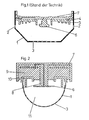
- the detector shown in Fig. 1 consists of a metallic hood 1, which has openings 2 and 3 for the entry of the surrounding air.
- a labyrinth 4 made of highly insulating plastic is arranged inside the hood 1, and a number of it is arranged in a ring shape inside Neter webs 5 for extending the creepage distances.
- the stamp-shaped central electrode 6 is located in the middle of the labyrinth 4.
- the outer electrode is formed by the metallic hood 1.
- the two electrodes are connected to an insulating part 7 by connecting means (not shown), some of which are detachable.
- the insulating part 7 and the labyrinth 4 are made of the same plastic, preferably polycarbonate, for. B. Makrolon ".
- the ionization fire detector also consists of a metallic hood 1, which has openings 3 for the entry of the surrounding air.
- Thermoplastic polyesters ie polycondensation products of carbonic acid with diols, are suitable as the material for the first region 8. These polycarbonates are resistant to water, neutral salt solutions, mineral acids, for example also to hydrofluoric acid, aqueous solutions of oxidizing agents, hydrocarbons, oils, fats, etc. In particular, this area of the insulation section is made from Makrolon @ .
- the second area 9 is preferably made of a thermoset made of epoxies with polyols.
- the electronic components of the ionization fire detector can be embedded in this potting compound made of epoxy resin.
- the epoxy resins are resistant to atmospheric influences, water, acids, alkalis, oil, petrol, benzene, etc.
- the third region 10 is preferably produced from a polycondensation product of polyhydric alcohols (diols, polyols) with polybasic carboxylic acids. These polyesters are resistant to all organic solvents, but are less resistant to water and alkalis as well as to acids above 70 ° C.
- one or more of the different areas 8, 9, 10 can be equipped with ring-shaped elevations for extending the creepage distance without the process for producing the insulating part becoming significantly more complicated.
- a major advantage of the ionization fire detector according to the invention is that the insulating ability of the insulating part 7 is maintained over substantially longer periods of time than in the known ionization fire detectors. If the surface resistance of one of the plastics forming the insulating part 7 is reduced due to the action of aggressive ingredients from the atmosphere or due to the slightest damage caused by the cleaning or drying agents, the insulation ability remains due to the different chemical composition of the individual areas received at least one of the other areas. When developing the technological procedural instructions for cleaning plastic parts, the chemical nature of the plastic parts is largely taken into account. However, since the composition of the dust deposited on the insulation section is not known, it is often necessary to use very active cleaning agents, e.g. B. Solutions from RBS.
- the detector parts In order to enable rational detector revision, the detector parts must be dried after cleaning, using water displacement agents such as isopropyl alcohol or freon. The maintenance of the surface quality of the plastic parts can therefore not be guaranteed in the long run. However, if the individual areas of the insulating part 7 are made of plastics of different chemical resistance, the risk that the insulating ability of the entire insulating part 7 will drop below an acceptable limit is considerably lower than with the known ionization fire detectors.
Landscapes
- Chemical & Material Sciences (AREA)
- Analytical Chemistry (AREA)
- Business, Economics & Management (AREA)
- Emergency Management (AREA)
- Physics & Mathematics (AREA)
- General Physics & Mathematics (AREA)
- Fire-Detection Mechanisms (AREA)
- Fire Alarms (AREA)
- Other Investigation Or Analysis Of Materials By Electrical Means (AREA)
Description
- Die Erfindung geht aus von einem lonisationsfeuermelder der im Oberbegriff des Anspruchs 1 definierten Gattung.
- lonisationsfeuermelder der oben angegebenen Art sind bekannt, beispielsweise aus der CH-PS Nr. 506148 oder der DE-AS Nr. 2130889. Bei diesen lonisationsfeuermeldern wird die in der Aussenatmosphäre zugänglichen lonisationskammer (Messkammer) befindliche Luft durch ein radioaktives Präparat ionisiert und auf Grund der an die beiden Elektroden der lonisationskammer angelegte Gleichspannung fliesst ein Ionenstrom zwischen den Elektroden. Treten Rauch, Brandaerosole oder andere Partikel durch die Kammeröffnungen in die lonisationskammert ein, so ändert sich der elektrische Strom. Die elektrische Schaltung wertet diese Stromänderung derart aus, dass bei einer bestimmten Herabsetzung der Leitfähigkeit in der lonisationskammer über die Leitungen ein Alarmsignal an eine Zentrale abgegeben wird. Bei bekannten derartigen Schaltungen liegt die lonisationskammer in Serie mit einem Widerstandselement, z. B. einer nahezu abgeschlossenen oder gegen Brandaerosole unempfindlichen zweiten Referenzionisationskammer, und die Potentialdifferenz zwischen beiden Kammern wird mit Hilfe eines hochohmigen Verstärkerelementes, z. B. eines Feldeffekttransistors, bestimmt. Eine weitere Möglichkeit besteht in der periodischen Abtastung der Aufladung der Elektroden der lonisationskammer.
- Da die verwendeten lonisationskammern im allgemeinen einen Widerstand von mehr als 1010 Ω besitzen und die elektrische Schaltung einen wesentlich höheren Eingangswiderstand haben muss, sind lonisationsfeuermelder sehr empfindlich auf Verunreinigungen, welche den elektrischen Widerstand des isolierenden Teils (Isolationsstrecke) zwischen den Elektroden der Messkammer herabsetzen. In gleicherweise wie Brandaerosole werden Partikeln aus der Umgebung des Melders, z. B. Staub, in die Messkammer hineintransportiert und dort abgelagert, wodurch der elektrische Widerstand der Isolationsstrecke abnimmt. Dies macht eine häufige Wartung von Feuermeldeanl'agen und eine Reinigung der lonisationsfeuermelder notwendig.
- Das Problem der Aufrechterhaltung des elektrischen Widerstands wurde gemäss DE-AS Nr. 2130889 dadurch gelöst, dass die Isolationsstrecke im Inneren der als Aussenelektrode dienenden, Öffnungen zum Eintritt der umgebenden Luft aufweisenden Haube durch ein aus dem gleichen hochisolierenden Kunststoff bestehendes Labyrinth abgedeckt wurde. Dadurch wurde die Kriechstrecke zwischen der Mittelelektrode und der Entgegenelektrode vor der Verschmutzung geschützt und der der Verschmutzung ausgesetzte Kriechweg wurde durch die ringförmigen Stege des Labyrinths um mehr als das Vierfache verlängert. Es war so möglich den Zeitraum bis zum Unwirksamwerden des Melders erheblich zu verlängern, d. h. die Serviceintervalle konnten vergrössert werden. Kunststoffe unterliegen jedoch der natürlichen Alterung, die durch Einwirkung des Luftsauerstoffs (z. T. auch Ozon) oder agressiver Ingredienzien in der umgebenden Luft und in den bei der Melderrevision verwendeten Reinigungsmitteln beschleunigtwerden kann. Solchekorrosiven Stoffe sind in der normalen Umgebungsluft zwar in äusserst geringer Konzentration vorhanden, können in spezieller Umgebung jedoch beträchtliche Werte annehmen. Schliesslich ist die Dauer der Einwirkung nicht zu vernachlässigen sowie die Tatsache, dass durch die im Melder vorhandene radioaktive Quelle die Luft ionisiert wird, wodurch Ozon und andere, das Meldermaterial angreifende Stoffe gerade im Melderinnern gebildet werden. Da die Atmosphäre zwischen das Labyrinth und die Isolierstrecke eindringen kann, bleibt das Problem der Alterung der Isolationsstrecke bestehen.
- Die Reinigung der Melder bei der Revision stellte auch bisher kein Problem dar, aber die wiederholte Reinigung unter Aufrechterhaltung der hohen Oberflächenisolationswerte von ca. 1010 Q über längere Zeit war immer noch problematisch.
- Die Suche nach Materialien mit genügend hoher Widerstandsfähigkeit gegen Umwelteinflüsse (Lösungsmitteldämpfe, Insektizide} führte zu keinem befriedigenden Ergebnis, da es nicht möglich war, einen Kunststoff zu finden, der optimale Eigenschaften im Hinblick auf sämtliche Umwelteinflüsse besitzt.
- Die Aufgabe der vorliegenden Erfindung besteht darin, einen lonisationsfeuermelder der eingangs genannten Art zu schaffen, der die vorstehend erwähnten Nachteile nicht aufweist und bei dem insbesondere der Isolationswert des isolierenden Teils zwischen den Elektroden über einen längeren Zeitraum erhalten bleibt.
- Diese Aufgabe wird erfindungsgemäss durch die im kennzeichnenden Teil des Anspruchs 1 definierten Merkmale gelöst.
- Gemäss einer bevorzugten Ausführungsform des erfindungsgemässen lonisationsmelders weist das isolierende Teil drei aus unterschiedlichen isolierenden Materialien bestehende Bereiche auf. Besonders bevorzugt ist es, den ersten Bereich beispielsweise aus einem Polycarbonat, den zweiten Teil beispielsweise aus einem Epoxidharz und den dritten Bereich beispielsweise aus einem Polyester herzustellen.
- Im folgenden werden anhand der Fig. 1 ein lonisationsfeuermelder des Standes der Technik und anhand der Fig. 2 eine beispielsweise gewählte Ausführungsform eines erfindungsgemässen lonisationsfeuermelders beschrieben. Es zeigen:
- Fig. 1 einen lonisationsfeuermelder nach dem Stand der Technik im Schnitt;
- Fig. 2 einen lonisationsfeuermelder nach der Erfindung im Schnitt.
- Der in Fig. 1 dargestellte Melder besteht aus einer metallischen Haube 1, welche Öffnungen 2 und 3 zum Eintritt der umgebenden Luft aufweist. Im Inneren der Haube 1 ist ein Labyrinth 4 aus hochisolierendem Kunststoff angeordnet, weiches im Inneren eine Anzahl kreisringförmig angeordneter Stege 5 zur Verlängerung der Kriechwege aufweist. In der Mitte des Labyrinths 4 befindet sich die stempelförmige Mittelelektrode 6. Die Aussenelektrode wird von der metallischen Haube 1 gebildet. Die beiden Elektroden sind durch nichtdargestellte Verbindungsmittel - zum Teil lösbar - mit einem isolierenden Teil 7 verbunden. Das isolierende Teil 7 und das Labyrinth 4 sind aus dem gleichen Kunststoff, vorzugsweise Polycarbonat, z. B. Makrolon", hergestellt.
- In Fig. 2 ist eine Ausführungsform eines erfindungsgemässen lonisationsfeuermelders im Schnitt dargestellt. Der lonisationsfeuermelder besteht ebenfalls aus einer metallischen Haube 1, welche Öffnungen 3 zum Eintritt der umgebenden- Luft aufweist. Die Gegenelektrode 6, die in der Mitte der der Aussenatmosphäre züganglichen lonisationskammer 11 angeordnet ist, befindet sich auf einer zentralen Erhöhung 8 des isolierenden Teils 7. Zwischen der Mittelelektrode 6 und der die andere Elektrode bildenden metallischen Haube 1 ist das isolierende Teil in einen ersten Bereich 8 aus einem Polycarbonat, einen zweiten Bereich 9, welcher aus einem Epoxidharz besteht, und einen dritten Bereich 10, welcher aus einem Polyester besteht, unterteilt.
- Durch diese Anordnung wird erreicht, dass ein Kriechstrom, der sich zwischen der Mittelelektrode 6 und der die Aussenelektrode bildenden metallischen Haube 1 ausbildet, über drei Isolierstrekken aus unterschiedlichem Kunststoffmaterial führt. Als Material für den ersten Bereich 8 kommen thermoplastische Polyester, d. h. Polykondensationsprodukte der Kohlensäure mit Diolen, in Frage. Diese Polycarbonate sind beständig gegen Wasser, Neutralsalzlösungen, Mineralsäuren, beispielsweise auch gegen Flusssäure, wässerige Lösungen von Oxidationsmitteln, Kohlenwasserstoffe, Öle, Fette usw. Insbesondere wird dieser Bereich der Isolationsstrecke aus Makrolon@ hergestellt. Der zweite Bereich 9 wird vorzugsweise aus einem Duroplast aus Epoxiden mit Polyolen hergestellt. In diese aus Epoxidharz gebildete Vergussmasse können die elektronischen Bauteile des lonisationsfeuermelders eingebettet werden. Die Epoxidharze sind widerstandsfähig gegen atmosphärische Einflüsse, gegen Wasser, Säuren, Laugen, Öl, Benzin, Benzol usw. Der dritte Bereich 10 wird vorzugsweise aus einem Polykondensationsprodukt von mehrwertigen Alkoholen (Diolen, Polyolen) mit mehrbasischen Carbonsäuren hergestellt. Diese Polyester sind gegen alle organischen Lösungsmittel beständig, sind jedoch gegen Wasser und Alkalien sowie gegen Säuren oberhalb von 70° C, weniger beständig. Zur Verbesserung der Isolationsfähigkeit des isolierenden Teils 7 können ein oder mehrere der verschiedenen Bereiche 8, 9, 10 mit ringförmigen Erhebungen zur Verlängerung des Kriechwegs ausgestattet werden, ohne dass dadurch das Verfahren zur Herstellung des isolierenden Teils wesentlich komplizierter wird.
- Ein wesentlicher Vorteil des erfindungsgemässen lonisationsfeuermelders besteht darin, dass die Isolationsfähigkeit des isolierenden Teils 7 über wesentlich längere Zeiträume erhalten bleibt als bei den bekannten lonisationsfeuermeldern. Wird nämlich der Oberflächenwiderstand eines der das isolierende Teil 7 bildenden Kunststoffe durch die Einwirkung agressiver Ingredienzien aus der Atmosphäre oder durch wenn auch noch so geringe Schädigung durch die Reinigungs- oder Trocknungsmittel verringert, so bleibt aufgrund der unterschiedlichen chemischen Zusammensetzung der einzelnen Bereiche immer noch die lsolationsfähigkeit mindestens eines der anderen Bereiche erhalten. Es wird zwar bei der Ausarbeitung der technologischen Verfahrensvorschriften für das Reinigen von Kunststoffteilen weitgehend auf die chemische Beschaffenheit der Kunststoffteile Rücksicht genommen. Da jedoch die Zusammensetzung des auf der Isolationsstrecke abgeschiedenen Staubs nicht bekannt ist, muss häufig mit sehr aktiven Reinigungsmitteln, z. B. Lösungen von RBS, gearbeitet werden. Um eine rationelle Melderrevision zu ermöglichen, müssen die Melderteile im Anschluss an die Reinigung getrocknet werden, wobei Wasserverdrängungsmittel, wie Isopropylalkohol oder Freon, angewendet werden. Die Aufrechterhaltung der Oberflächenbeschaffenheit der Kunststoffteile kann daher auf die Dauer nicht garantiert werden. Werden jedoch die einzelnen Bereiche des isolierenden Teils 7 aus Kunststoffen unterschiedlicher chemischer Widerstandsfähigkeit hergestellt, so ist die Gefahr, dass die Isoliationsfähigkeit des gesamten isolierenden Teils 7 unter eine noch akzeptable Grenze sinkt, erheblich geringer als bei den bekannten lonisationsfeuermeldern.
- Selbstverständlich ist es möglich, anstelle der vorstehend genannten Kunststoffe andere Kunststoffe einzusetzen, wenn darauf geachtet wird, dass die Resistenz gegen äussere Einwirkungen bei den verwendeten Kunststoffen möglichst unterschiedlich ist. Der Erfindungsgedanke, nämlich Isolationsstrecken dadurch widerstandsfähiger zu machen, dass sie in Bereiche unterschiedlicher chemischer Zusammensetzung aufgeteilt werden, ist vorstehend für lonisationsbrandmelder beschrieben. Aber auch die Isolationsstrecken anderer Brandmelder, bei denen es auf einen hohen Eingangswiderstand einer Verstärkungsstufe ankommt, können dadurch erheblich verbessert werden, dass man bei der Herstellung der Isolationsstrecken Bereiche unterschiedlicher Kunststoffe in Serie anordnet.
Claims (3)
Priority Applications (1)
| Application Number | Priority Date | Filing Date | Title |
|---|---|---|---|
| AT83103225T ATE17409T1 (de) | 1982-04-08 | 1983-03-31 | Ionisationsfeuermelder. |
Applications Claiming Priority (2)
| Application Number | Priority Date | Filing Date | Title |
|---|---|---|---|
| CH218482 | 1982-04-08 | ||
| CH2184/82 | 1982-04-08 |
Publications (2)
| Publication Number | Publication Date |
|---|---|
| EP0091623A1 EP0091623A1 (de) | 1983-10-19 |
| EP0091623B1 true EP0091623B1 (de) | 1986-01-08 |
Family
ID=4227850
Family Applications (1)
| Application Number | Title | Priority Date | Filing Date |
|---|---|---|---|
| EP83103225A Expired EP0091623B1 (de) | 1982-04-08 | 1983-03-31 | Ionisationsfeuermelder |
Country Status (10)
| Country | Link |
|---|---|
| US (1) | US4582996A (de) |
| EP (1) | EP0091623B1 (de) |
| JP (1) | JPS58186896A (de) |
| AT (1) | ATE17409T1 (de) |
| AU (1) | AU554415B2 (de) |
| BR (1) | BR8301799A (de) |
| CA (1) | CA1217284A (de) |
| DE (1) | DE3361760D1 (de) |
| ES (1) | ES8404079A1 (de) |
| NO (1) | NO831246L (de) |
Families Citing this family (3)
| Publication number | Priority date | Publication date | Assignee | Title |
|---|---|---|---|---|
| JPS6044194U (ja) * | 1983-09-05 | 1985-03-28 | 能美防災工業株式会社 | イオン化式煙感知器の耐熱ケ−ス |
| DE4028167A1 (de) * | 1990-09-05 | 1992-03-12 | Esser Sicherheitstechnik | Ionisationsbrandmelder |
| US5485144A (en) * | 1993-05-07 | 1996-01-16 | Pittway Corporation | Compensated ionization sensor |
Family Cites Families (7)
| Publication number | Priority date | Publication date | Assignee | Title |
|---|---|---|---|---|
| CH506148A (fr) * | 1969-02-28 | 1971-04-15 | Mefina Sa | Dispositif détecteur de fumée |
| BE731052A (fr) * | 1969-04-04 | 1969-10-06 | Acec | Procédés de fabrication de produits stratifiés isolants |
| ZA704724B (en) * | 1969-07-22 | 1971-03-31 | Nittan Co Ltd | Ionization smoke detector |
| CH508251A (de) * | 1970-07-23 | 1971-05-31 | Cerberus Ag | Ionisationsfeuermelder |
| DE2143365B2 (de) * | 1971-08-30 | 1977-09-08 | Siemens AG, 1000 Berlin und 8000 München | Anordnung zum isolieren von elektroden |
| JPS5823705B2 (ja) * | 1977-08-24 | 1983-05-17 | 株式会社東芝 | 放射線検出器 |
| JPS57135977A (en) * | 1981-02-16 | 1982-08-21 | Canon Kk | Photoelectrical indicator |
-
1983
- 1983-03-21 US US06/476,992 patent/US4582996A/en not_active Expired - Fee Related
- 1983-03-29 AU AU12958/83A patent/AU554415B2/en not_active Ceased
- 1983-03-31 AT AT83103225T patent/ATE17409T1/de not_active IP Right Cessation
- 1983-03-31 EP EP83103225A patent/EP0091623B1/de not_active Expired
- 1983-03-31 DE DE8383103225T patent/DE3361760D1/de not_active Expired
- 1983-04-06 CA CA000425329A patent/CA1217284A/en not_active Expired
- 1983-04-07 BR BR8301799A patent/BR8301799A/pt not_active IP Right Cessation
- 1983-04-07 NO NO831246A patent/NO831246L/no unknown
- 1983-04-08 ES ES521785A patent/ES8404079A1/es not_active Expired
- 1983-04-08 JP JP58061051A patent/JPS58186896A/ja active Pending
Also Published As
| Publication number | Publication date |
|---|---|
| ES521785A0 (es) | 1984-04-01 |
| US4582996A (en) | 1986-04-15 |
| ATE17409T1 (de) | 1986-01-15 |
| AU554415B2 (en) | 1986-08-21 |
| ES8404079A1 (es) | 1984-04-01 |
| NO831246L (no) | 1983-10-10 |
| AU1295883A (en) | 1983-10-13 |
| EP0091623A1 (de) | 1983-10-19 |
| DE3361760D1 (en) | 1986-02-20 |
| JPS58186896A (ja) | 1983-10-31 |
| BR8301799A (pt) | 1983-12-20 |
| CA1217284A (en) | 1987-01-27 |
Similar Documents
| Publication | Publication Date | Title |
|---|---|---|
| DE3530758C2 (de) | ||
| DE60201390T2 (de) | Kondensatormikrofon und Verfahren zur dessen Herstellung | |
| DE3119495A1 (de) | "annaeherungs-schalter" | |
| DE4028062C2 (de) | Gassensoranordnung mit FET mit unterbrochenem Gate | |
| DE2652970B2 (de) | lonisations-Brandmelder | |
| WO2000026656A1 (de) | Gasdetektion nach dem prinzip einer messung von austrittsarbeiten | |
| DE112016007051B4 (de) | Ionenanalysevorrichtung | |
| EP0091623A1 (de) | Ionisationsfeuermelder | |
| DE1906075A1 (de) | Verbesserte Alarmvorrichtung und UEberwachungsanlage fuer deren Anwendung | |
| DE2743761A1 (de) | Rauchdetektor | |
| DE3904979C2 (de) | ||
| DE1589987A1 (de) | Ionisationskammeranzeigevorrichtung | |
| CH624447A5 (en) | Surrounding fence with an alarm device for security-threatened installations | |
| EP0111012B1 (de) | Rauchsensor des ionisationstyps | |
| DE69810182T2 (de) | Mehrelektroden-Partikeldetektor und Herstellungsverfahren desselben | |
| DE2546970C3 (de) | Ionisations-Rauchmelder | |
| DE3501356C2 (de) | ||
| DE1616020B2 (de) | Feuermeldevorrichtung | |
| DE2700906C2 (de) | Anordnung zur Brandmeldung | |
| DE3030453A1 (de) | Antistatische beschichtung und verfahren zu ihrer herstellung | |
| EP0841146B1 (de) | Leitfähige Bereiche auf isolierenden Kunststoffen | |
| DE2363284A1 (de) | Ionisationsvorrichtung | |
| DE2435053B2 (de) | Ionisationsfeuerdetektor | |
| DE2362084C3 (de) | Verfahren zur Fruherkennung von toxischen Verunreinigungen in Wasser mit Hilfe von Testfischen | |
| DE3200620A1 (de) | Ionisations-rauchdetektor |
Legal Events
| Date | Code | Title | Description |
|---|---|---|---|
| PUAI | Public reference made under article 153(3) epc to a published international application that has entered the european phase |
Free format text: ORIGINAL CODE: 0009012 |
|
| 17P | Request for examination filed |
Effective date: 19830331 |
|
| AK | Designated contracting states |
Designated state(s): AT BE CH DE FR GB IT LI NL SE |
|
| GRAA | (expected) grant |
Free format text: ORIGINAL CODE: 0009210 |
|
| AK | Designated contracting states |
Designated state(s): AT BE CH DE FR GB IT LI NL SE |
|
| REF | Corresponds to: |
Ref document number: 17409 Country of ref document: AT Date of ref document: 19860115 Kind code of ref document: T |
|
| ITF | It: translation for a ep patent filed | ||
| REF | Corresponds to: |
Ref document number: 3361760 Country of ref document: DE Date of ref document: 19860220 |
|
| ET | Fr: translation filed | ||
| PLBE | No opposition filed within time limit |
Free format text: ORIGINAL CODE: 0009261 |
|
| STAA | Information on the status of an ep patent application or granted ep patent |
Free format text: STATUS: NO OPPOSITION FILED WITHIN TIME LIMIT |
|
| 26N | No opposition filed | ||
| PGFP | Annual fee paid to national office [announced via postgrant information from national office to epo] |
Ref country code: CH Payment date: 19900118 Year of fee payment: 8 |
|
| PGFP | Annual fee paid to national office [announced via postgrant information from national office to epo] |
Ref country code: FR Payment date: 19900202 Year of fee payment: 8 |
|
| PGFP | Annual fee paid to national office [announced via postgrant information from national office to epo] |
Ref country code: AT Payment date: 19900207 Year of fee payment: 8 |
|
| PGFP | Annual fee paid to national office [announced via postgrant information from national office to epo] |
Ref country code: SE Payment date: 19900221 Year of fee payment: 8 |
|
| PGFP | Annual fee paid to national office [announced via postgrant information from national office to epo] |
Ref country code: BE Payment date: 19900226 Year of fee payment: 8 |
|
| PGFP | Annual fee paid to national office [announced via postgrant information from national office to epo] |
Ref country code: DE Payment date: 19900227 Year of fee payment: 8 |
|
| PGFP | Annual fee paid to national office [announced via postgrant information from national office to epo] |
Ref country code: GB Payment date: 19900228 Year of fee payment: 8 |
|
| ITTA | It: last paid annual fee | ||
| PGFP | Annual fee paid to national office [announced via postgrant information from national office to epo] |
Ref country code: NL Payment date: 19900331 Year of fee payment: 8 |
|
| PG25 | Lapsed in a contracting state [announced via postgrant information from national office to epo] |
Ref country code: LI Effective date: 19910331 Ref country code: GB Effective date: 19910331 Ref country code: CH Effective date: 19910331 Ref country code: BE Effective date: 19910331 Ref country code: AT Effective date: 19910331 |
|
| PG25 | Lapsed in a contracting state [announced via postgrant information from national office to epo] |
Ref country code: SE Effective date: 19910401 |
|
| BERE | Be: lapsed |
Owner name: CERBERUS A.G. Effective date: 19910331 |
|
| PG25 | Lapsed in a contracting state [announced via postgrant information from national office to epo] |
Ref country code: NL Effective date: 19911001 |
|
| NLV4 | Nl: lapsed or anulled due to non-payment of the annual fee | ||
| GBPC | Gb: european patent ceased through non-payment of renewal fee | ||
| PG25 | Lapsed in a contracting state [announced via postgrant information from national office to epo] |
Ref country code: FR Effective date: 19911129 |
|
| REG | Reference to a national code |
Ref country code: CH Ref legal event code: PL |
|
| PG25 | Lapsed in a contracting state [announced via postgrant information from national office to epo] |
Ref country code: DE Effective date: 19920101 |
|
| REG | Reference to a national code |
Ref country code: FR Ref legal event code: ST |
|
| EUG | Se: european patent has lapsed |
Ref document number: 83103225.5 Effective date: 19911108 |