EP0091608B1 - Entkopplungsvorrichtung für Schaltgestänge - Google Patents
Entkopplungsvorrichtung für Schaltgestänge Download PDFInfo
- Publication number
- EP0091608B1 EP0091608B1 EP83103153A EP83103153A EP0091608B1 EP 0091608 B1 EP0091608 B1 EP 0091608B1 EP 83103153 A EP83103153 A EP 83103153A EP 83103153 A EP83103153 A EP 83103153A EP 0091608 B1 EP0091608 B1 EP 0091608B1
- Authority
- EP
- European Patent Office
- Prior art keywords
- gear selector
- uncoupling
- intermediate piece
- gear
- rods
- Prior art date
- Legal status (The legal status is an assumption and is not a legal conclusion. Google has not performed a legal analysis and makes no representation as to the accuracy of the status listed.)
- Expired
Links
- 230000008878 coupling Effects 0.000 claims description 9
- 238000010168 coupling process Methods 0.000 claims description 9
- 238000005859 coupling reaction Methods 0.000 claims description 9
- 238000000034 method Methods 0.000 claims description 2
- 230000008569 process Effects 0.000 claims description 2
- 238000006073 displacement reaction Methods 0.000 claims 1
- 230000005540 biological transmission Effects 0.000 description 8
- 230000007246 mechanism Effects 0.000 description 4
- 230000009191 jumping Effects 0.000 description 3
- 230000037230 mobility Effects 0.000 description 2
- 230000004048 modification Effects 0.000 description 2
- 238000012986 modification Methods 0.000 description 2
- 238000010276 construction Methods 0.000 description 1
- 230000005284 excitation Effects 0.000 description 1
- 230000005021 gait Effects 0.000 description 1
- 230000005484 gravity Effects 0.000 description 1
Images
Classifications
-
- F—MECHANICAL ENGINEERING; LIGHTING; HEATING; WEAPONS; BLASTING
- F16—ENGINEERING ELEMENTS AND UNITS; GENERAL MEASURES FOR PRODUCING AND MAINTAINING EFFECTIVE FUNCTIONING OF MACHINES OR INSTALLATIONS; THERMAL INSULATION IN GENERAL
- F16H—GEARING
- F16H61/00—Control functions within control units of change-speed- or reversing-gearings for conveying rotary motion ; Control of exclusively fluid gearing, friction gearing, gearings with endless flexible members or other particular types of gearing
- F16H61/26—Generation or transmission of movements for final actuating mechanisms
-
- F—MECHANICAL ENGINEERING; LIGHTING; HEATING; WEAPONS; BLASTING
- F16—ENGINEERING ELEMENTS AND UNITS; GENERAL MEASURES FOR PRODUCING AND MAINTAINING EFFECTIVE FUNCTIONING OF MACHINES OR INSTALLATIONS; THERMAL INSULATION IN GENERAL
- F16H—GEARING
- F16H59/00—Control inputs to control units of change-speed- or reversing-gearings for conveying rotary motion
- F16H59/02—Selector apparatus
- F16H59/04—Ratio selector apparatus
- F16H59/042—Ratio selector apparatus comprising a final actuating mechanism
-
- F—MECHANICAL ENGINEERING; LIGHTING; HEATING; WEAPONS; BLASTING
- F16—ENGINEERING ELEMENTS AND UNITS; GENERAL MEASURES FOR PRODUCING AND MAINTAINING EFFECTIVE FUNCTIONING OF MACHINES OR INSTALLATIONS; THERMAL INSULATION IN GENERAL
- F16H—GEARING
- F16H59/00—Control inputs to control units of change-speed- or reversing-gearings for conveying rotary motion
- F16H59/02—Selector apparatus
- F16H59/0208—Selector apparatus with means for suppression of vibrations or reduction of noise
-
- Y—GENERAL TAGGING OF NEW TECHNOLOGICAL DEVELOPMENTS; GENERAL TAGGING OF CROSS-SECTIONAL TECHNOLOGIES SPANNING OVER SEVERAL SECTIONS OF THE IPC; TECHNICAL SUBJECTS COVERED BY FORMER USPC CROSS-REFERENCE ART COLLECTIONS [XRACs] AND DIGESTS
- Y10—TECHNICAL SUBJECTS COVERED BY FORMER USPC
- Y10T—TECHNICAL SUBJECTS COVERED BY FORMER US CLASSIFICATION
- Y10T74/00—Machine element or mechanism
- Y10T74/20—Control lever and linkage systems
- Y10T74/20006—Resilient connections
-
- Y—GENERAL TAGGING OF NEW TECHNOLOGICAL DEVELOPMENTS; GENERAL TAGGING OF CROSS-SECTIONAL TECHNOLOGIES SPANNING OVER SEVERAL SECTIONS OF THE IPC; TECHNICAL SUBJECTS COVERED BY FORMER USPC CROSS-REFERENCE ART COLLECTIONS [XRACs] AND DIGESTS
- Y10—TECHNICAL SUBJECTS COVERED BY FORMER USPC
- Y10T—TECHNICAL SUBJECTS COVERED BY FORMER US CLASSIFICATION
- Y10T74/00—Machine element or mechanism
- Y10T74/20—Control lever and linkage systems
- Y10T74/20012—Multiple controlled elements
- Y10T74/20018—Transmission control
Definitions
- the invention relates to a decoupling device for linkage, in particular for the shift linkage arranged between the gearbox and shift lever of a motor vehicle, with a decoupling element which can be moved perpendicularly to the longitudinal axis of the linkage and which is arranged on the interlocking ends of two rotatable and axially displaceable shifting rods, which are mounted in a tube piece Allows the decoupled shift rod back and forth.
- the engine and transmission block of a motor vehicle is arranged transversely to the longitudinal axis of the vehicle in order to save space, there is a risk of gear jumping. Due to roadway excitation and applied engine torque, rotary movements of the transverse engine and transmission block about its longitudinal axis are generated and the shift linkage is set in vibration such that the drive block and shift linkage oscillate against each other. With correspondingly large vibration amplitudes, this can lead to the automatic disengagement of the currently engaged gear.
- a gear selection mechanism for a vehicle which has a coupling for coupling at one end to a gear selector lever of the vehicle and for coupling at the other end to a transmission of the vehicle.
- the coupler in operation, transmits movements of the lever to the transmission to actuate the transmission, the coupler having first and second parts for mobility relative to one another, and the mechanism also includes a locking device which selectively connects either the first and the second part can be actuated with one another for transferability of movement through the coupling or for releasing the first and the second part from one another for relative movability. With relative mobility, the coupling does not transmit the movement of the lever to the gearbox.
- the locking device is operated manually from the vehicle's bicycle by the ignition switch.
- the locking device of the known mechanism is intended to reduce to a minimum the vehicle being driven away by an unauthorized person.
- the unauthorized person can start the engine of the vehicle if he short-circuits the electrical switch, but he cannot drive the vehicle away since the transmission remains idle when the gear lever is moved.
- the known mechanism is an anti-theft device that is built into the shift linkage.
- the invention is intended to prevent gait jumping, which can only occur when the motor vehicle is running and a gear is engaged, but not when idling.
- the object of the invention is therefore to provide a space-saving decoupling device consisting of a few and simply designed individual parts, which effectively prevents gang jumping.
- This is advantageously achieved according to the invention in that an intermediate piece is provided between the two non-rotatably connected ends of the shift rods, which controls the decoupling process, is displaceable in the axial direction and in the direction of its longitudinal axis and cooperates at one end with the inner surface of the pipe piece.
- the decoupling element which interacts with a recess in the shift rod actuated by the shift lever is inserted, the decoupling element being coupled by moving transversely to the longitudinal axis of the intermediate piece when the shift rod is moved from the decoupled state in the axial direction and relative to the intermediate piece, coupling the ends of the two shift rods effected in the axial direction.
- the intermediate piece according to the invention enables the decoupling device to be constructed in a simple and space-saving manner and ensures high operational reliability, cost-effective production and assembly and a long service life.
- the end of the shift rod actuated by the shift lever has a tongue which, together with the intermediate piece displaceable in the axial direction and in the direction of its longitudinal axis, projects into a groove at the end of the shift rod connected to the gearbox, so that the Gear selection, both shift rods can perform a rotary movement together.
- the rotary movement can also be transmitted by means of a pin that can be moved in a longitudinal slot or a sliding block.
- the intermediate piece can be mounted in the axial direction and in the direction of its longitudinal axis on the tongue of the shift rod actuated by the shift lever, and the decoupling element, which can be moved transversely to the longitudinal axis of the intermediate piece, can have depressions in the tongue and / or the groove of the shift rods for producing a positive connection work together. Furthermore, the intermediate piece can have a latching device which is arranged at the end of the intermediate piece between the two shift rods and engages in depressions in the tube piece surrounding the ends of the shift rods.
- a non-positive connection can also be used if the decoupling element and the intermediate piece are designed accordingly.
- the end of the intermediate piece which cooperates with the tube piece surrounding the ends of the shift rods has a frictional connection the inner surface of the pipe section.
- the shift rod 1 consists of the shift rod 1 connected to the shift lever of the motor vehicle, the shift rod 2 connected to the transmission, the intermediate piece 3 and the pipe section 4.
- the shift rod 1 has a tongue 5 at its end, which extends into a groove 6 the shift rod 2 engages.
- the tongue 5 has a shoulder 10 which bears against the inner wall of the groove 6 and ensures that a rotary movement of the shift rod 1 is transmitted to the shift rod 2 both in the coupled and in the decoupled state.
- the rotary movement can also be transmitted by means of a pin that can be moved in a longitudinal slot or a sliding block.
- the intermediate piece 3 is slidably mounted on the tongue 5.
- One end of the intermediate piece 3 is provided with a latching device 11 which is located in an intermediate space between the two shift rods 1 and 2 and whose latching body 16 counters in depressions 17, 18 and 19 located on the inner wall of the tubular piece 4.
- a ball 21 or a roller sits in a recess 20, which cooperates with recesses 22 and 23 in the tongue 5 and the groove 6.
- the recess 23 in the groove 6 has lateral extensions 24 and 25, which form a type of catching device for the ball 21.
- a pin 30 inserted into the tongue 5 engages in an elongated hole 31 of the intermediate piece 3, in order to enable a forced connection between the shift rod 1 and the intermediate piece 3, if necessary.
- bearing rings 35 and 36 are arranged for mounting the shift rods 1 and 2.
- the rotary movements are transmitted through the tongue 5 and the groove 6 to the transmission.
- the gears are switched on and off by moving the shift rod 1 in the axial direction.
- the ball 21 occurs because the intermediate piece 3 is initially held by the locking body 16, something out of the recess 22 and enters the recess 23, so that the shift rods 1 and 2 are positively coupled to each other, and the shift rod 1, the shift rod 2nd as well as the intermediate piece 3, whose latching body 16 snaps into the next recess 18 or 19 in the pipe section 4, depending on the switching direction.
- the distance between the recesses 17, 18 and 19 corresponds to the switching path.
- the two shift rods 1 and 2 are again free of force and the two recesses 22 and 23 lie exactly one above the other, so that the ball 21 or the roller enters the recess 22 by gravity or additionally by each 27 and the decoupled state 1 is restored.
- the shift rod 2 can then perform back and forth movements without being transmitted to the shift rod 1 and the shift lever.
- FIGS. 2 and 3 differ from the embodiment according to FIG. 1 essentially in that a non-positive connection between the two shift rods 1 and 2 is made during gear shifting instead of a positive connection.
- a friction surface 40 which is in frictional engagement with the inner surface of the pipe section 4.
- the ball 21 is also in frictional engagement with the inner wall of the groove 6 when it is pressed out of the recess 21 during gear shifting.
- a clamping body 41 as is the case in FIG. 3, can also be used, the lower rounded end of which engages in a rounded recess 42.
- the shift rods 1 and 2 with the tongue 5 and the groove 6 and the pipe section 4 can also be formed symmetrically in FIG. 1, so that two intermediate pieces 3 with balls 21 act opposite one another as coupling points.
Landscapes
- Engineering & Computer Science (AREA)
- General Engineering & Computer Science (AREA)
- Mechanical Engineering (AREA)
- Gear-Shifting Mechanisms (AREA)
- Arrangement Or Mounting Of Control Devices For Change-Speed Gearing (AREA)
Description
- Die Erfindung betrifft eine Entkopplungsvorrichtung für Gestänge, insbesondere für das zwischen Getriebe und Schalthebel eines Kraftfahrzeuges angeordnete Schaltgestänge, mit einem senkrecht zur Längsachse des Gestänges bewegbaren Entkopplungselement, das an den in einem Rohrstück gelagerten, ineinandergreifenden Enden zweier drehbaren und axial verschiebbaren Schaltstangen angeordnet ist und eine Hin- und Herbewegung der entkoppelten Schaltstange zuläßt.
- Wird aus Platzersparnisgründen der Motor-und Getriebeblock eines Kraftfahrzeuges quer zur Längsachse des Fahrzeuges angeordnet, so besteht die Gefahr des Gangspringens. Durch Fahrbahnanregung und aufgebrachtes Motordrehmoment werden Drehbewegungen des querliegenden Motor- und Getriebeblocks um seine Längsachse erzeugt und das Schaltgestänge dadurch derart in Schwingungen versetzt, daß Antriebsblock und Schaltgestänge gegeneinander schwingen. Dies kann bei entsprechend großen Schwingungsamplituden zum selbsttätigen Ausschalten des gerade eingelegten Ganges führen.
- Durch die DE-OS 22 06 715 ist ein Gangwahlmechanismus für ein Fahrzeug bekannt, der eine Koppel zur Kopplung an einem Ende mit einem Gangwahlhebel des Fahrzeuges und zur Kopplung am anderen Ende mit einem Getriebe des Fahrzeuges aufweist. Die Koppel überträgt im Betrieb Bewegungen des Hebels auf das Getriebe zur Betätigung des Getriebes, wobei die Koppel ein erstes und ein zweites Teil zur Bewegbarkeit relativ zueinander aufweist, und zum Mechanismus ferner eine Sperreinrichtung gehört, die selektiv entweder zum Verbinden des ersten und des zweiten Teils miteinander zur Bewegungsübertragbarkeit durch die Koppel oder zu Lösen des ersten und des zweiten Teils voneinander zur Relativbewegbarkeit betätigbar ist. Bei Relativbewegbarkeit überträgt die Koppel die Bewegung des Hebels nicht auf das Getriebe. Die Sperreinrichtung wird von Hand aus dem Fahrrad des Fahrzeuges durch den Zündschalter betätigt.
- Durch die Sperreinrichtung des bekannten Mechanismus soll ein Wegfahren des Fahrzeuges durch einen Unbefugten auf ein Minimum reduziert werden. Der Unbefugte kann zwar den Motor des Fahrzeuges anlassen, wenn er den elektrischen Schalter kurzschließt, er kann aber mit dem Fahrzeug nicht wegfahren, da das Getriebe im Leerlauf bleibt, wenn der Schalthebel bewegt wird. Es handelt sich bei dem bekannten Mechanismus um eine Diebstahlsicherung, die in das Schaltgestänge eingebaut ist. Durch die Erfindung soll aber ein Gangspringen verhindert werden, das nur dann auftreten kann, wenn das Kraftfahrzeug fährt und ein Gang eingeschaltet ist, nicht dagegen im Leerlauf.
- Aufgabe der Erfindung ist es also, eine aus wenigen und einfach gestalteten Einzelteilen bestehende, platzsparende Entkopplungsvorrichtung zu schaffen, die das Gangspringen wirksam verhindert. Dies wird gemäß der Erfindung auf vorteilhafte Weise dadurch erreicht, daß zwischen den beiden drehfest miteinander verbundenen Enden der Schaltstangen ein den Entkopplungsvorgang steuerndes, in axialer Richtung sowie in Richtung seiner Längsachse verschiebbares und an seinem einen Ende mit der Innenfläche des Rohrstückes zusammenwirkendes Zwischenstück vorgesehen ist, in das das mit einer Vertiefung in der vom Schalthebel betätigten Schaltstange zusammenwirkende Entkopplungselement eingesetzt ist, wobei das Entkopplungselement durch eine Bewegung quer zur Längsachse des Zwischenstückes beim Verschieben der Schaltstange aus dem entkoppelten Zustand in axialer Richtung und relativ zum Zwischenstück eine Kopplung der Enden der beiden Schaltstangen in axialer Richtung bewirkt.
- Das erfindungsgemäße Zwischenstück ermöglicht einen einfachen und platzsparenden Aufbau der Entkopplungsvorrichtung und gewährleisten eine hohe Betriebssicherheit, eine kostengünstige Fertigung und Montage sowie eine lange Lebensdauer.
- Eine vorteilhafte Weiterbildung der Erfindung besteht darin, daß das Ende der vom Schalthebel betätigten Schaltstange eine Zunge aufweist, die zusammen mit dem in axialer Richtung und in Richtung seiner Längsachse verschiebbaren Zwischenstück in eine Nut am Ende der mit dem Getriebe verbundenen Schaltstange hineinragt, damit bei der Gangwahl beide Schaltstangen gemeinsam eine Drehbewegung ausführen können. Die Drehbewegung kann ebenfalls mittels eines in einem Längsschlitz verschiebbaren Stiftes oder eines Gleitsteines übertragen werden. Das Zwischenstück kann in axialer Richtung und in Richtung seiner Längsachse verschiebbar auf der Zunge der vom Schalthebel betätigten Schaltstange gelagert sein, und das quer zur Längsachse des Zwischenstückes verschiebbare Entkopplungselement kann mit Vertiefungen in der Zunge und/oder der Nut der Schaltstangen zur Herstellung einer formschlüssigen Verbindung zusammenwirken. Weiterhin kann das Zwischenstück eine Rasteinrichtung besitzen, die am Ende des Zwischenstückes zwischen den beiden Schaltstangen angeordnet ist und in Vertiefungen des die Enden der Schaltstangen umgebenden Rohrstückes einrastet.
- Statt einer formschlüssigen Verbindung der beiden Schaltstangen im gekoppelten Zustand kann aber auch bei entsprechender Ausbildung des Entkopplungselementes und des - Zwischenstückes eine kraftschlüssige Verbindung zur Anwendung kommen. In diesem Fall hat das mit dem die Enden der Schaltstangen umgebende Rohrstück zusammenwirkende Ende des Zwischenstückes einen Reibungsschluß mit der Innenfläche des Rohrstückes.
- Weitere Merkmale und Vorteile der Erfindung können aus der Zeichnung und der zugehörigen Beschreibung entnommen werden. In der Zeichnung sind mehrere Ausführungsbeispiele gemäß der Erfindung dargestellt, und zwar zeigt:
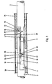
- Fig. 1 eine Entkopplungsvorrichtung deren Zwischenstück eine Rasteinrichtung und eine Kugel als Entkopplungselement aufweist, wobei sich die Kugel in Entkopplungsstelle befindet,
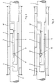
- Fig. 2 eine andere Ausführungsform der Entkopplungsvorrichtung, deren Zwischenstück eine Reibungsfläche und eine Kugel für einen Reibschluß zwischen den beiden Schaltstangen besitzt und
- Fig. 3 eine Abwandlung der Ausführungsform nach Fig. 2 mit einem Klemmkörper für den Reibschluß zwischen den beiden Schaltstangen.
- Die Entkopplungsvorrichtung nach Fig. 1 besteht aus der mit dem Schalthebel des Kraftfahrzeuges verbundenen Schaltstange 1, der mit dem Getriebe verbundenen Schaltstange 2, dem Zwischenstück 3 und dem Rohrstück 4. Die Schaltstange 1 besitzt an ihrem Ende eine Zunge 5, die in eine Nut 6 der Schaltstange 2 eingreift. Die Zunge 5 besitzt einen Ansatz 10, der an der Innenwand der Nut 6 anliegt und dafür sorgt, daß eine Drehbewegung der Schaltstange 1 sowohl im gekoppelten als auch im entkoppelten Zustand auf die Schaltstange 2 übertragen wird. Die Drehbewegung kann ebenfalls mittels eines in einem Längsschlitz verschiebbaren Stiftes oder eines Gleitsteines übertragen werden. Im Bereich der Nut 6 ist auf der Zunge 5 das Zwischenstück 3 verschiebbar gelagert. Das eine Ende des Zwischenstückes 3 ist mit einer Rasteinrichtung 11 versehen, die sich in einem Zwischenraum zwischen den beiden Schaltstangen 1 und 2 findet und deren Rastkörper 16 in an der Innenwand des Rohrstückes 4 befindlichen Vertiefungen 17, 18 und 19 einratet. Am anderen Ende des Zwischenstückes 3 sitzt in einer Ausnehmung 20 eine Kugel 21 oder eine Rolle, die mit Vertiefungen 22 und 23 in der Zunge 5 und der Nut 6 zusammenwirkt. Die Vertiefung 23 in der Nut 6 hat seitliche Erweiterungen 24 und 25, die eine Art Fangeinrichtung für die Kugel 21 bilden. Ein in die Zunge 5 eingesetzter Stift 30 greift in ein Langloch 31 des Zwischenstückes 3 ein, um gegebenenfalls eine zwangsweise Verbindung zwischen Schaltstange 1 und Zwischenstück 3 zu ermöglichen. An den Enden des Rohrstückes 4 sind Lagerringe 35 und 36 zur Lagerung der Schaltstangen 1 und 2 angeordnet.
- Bei der Ganganwahl werden die Drehbewegungen durch die Zunge 5 und die Nut 6 zum Getriebe übertagen. Das Ein- und Ausschalten der Gänge erfolgt durch Verschieben der Schaltstange 1 in axialer Richtung. Die Kugel 21 tritt dabei, da das Zwischenstück 3 durch den Rastkörper 16 zunächst festgehalten wird, etwas aus der Vertiefung 22 heraus und gelangt in die Vertiefung 23, so daß die Schaltstangen 1 und 2 formschlüssig miteinander gekoppelt sind, und die Schaltstange 1 die Schaltstange 2 sowie das Zwischenstück 3 mitnimmt, dessen Rastkörper 16 je nach Schaltrichtung in die nächste Vertiefung 18 bzw. 19 im Rohrstück 4 einrastet. Der Abstand zwischen den Vertiefungen 17,18 und 19 entspricht dem Schaltweg. Am Ende der Schaltbewegung sind die beiden Schaltstangen 1 und 2 wieder kräftefrei und die beiden Vertiefungen 22 und 23 liegen genau übereinander, so daß die Kugel 21 oder die Rolle durch die Schwerkraft oder zusätzlich durch die jeder 27 in die Vertiefung 22 gelangt und der entkoppelte Zustand nach Fig. 1 wieder hergestellt ist. Die Schaltstange 2 kann dann Hin-und Herbewegungen ausführen, ohne daß diese auf die Schaltstange 1 und den Schalthebel übertragen werden.
- Die Ausführungsformen der Erfindung nach Fig. 2 und 3 unterscheiden sich von der Ausführungsform nach Fig. 1 im wesentlichen dadurch, daß beim Gangschalten statt einer formschlüssigen Verbindung eine kraftschlüssige Verbindung zwischen den beiden Schaltstangen 1 und 2 hergestellt wird. An die Stelle der Rasteinrichtung 11 des Zwischenstückes 3 tritt eine Reibungsfläche 40, die mit der Innenfläche des Rohrstückes 4 in Reibungsschluß steht. Durch den Fortfall der Vertiefung 23 steht die Kugel 21 mit der Innenwand der Nut 6 ebenfalls in Reibungsschluß, wenn sie beim Gangschalten aus der Vertiefung 21 herausgedrückt wird. Statt der Kugel oder der Rolle nach Fig. 2 kann auch ein Klemmkörper41, wie dies in Fig. 3 der Fall ist, verwendet werden, dessen unteres abgerundetes Ende in eine abgerundete Vertiefung 42 eingreift. Die Schaltstangen 1 und 2 mit der Zunge 5 und der Nut 6 und das Rohrstück 4 können in Fig. 1 auch symmetrisch ausgebildet sein, so daß zwei Zwischenstücke 3 mit Kugeln 21 gegenüberliegend als Kopplungsstellen wirken.
- Die oben anhand der Zeichnung beschriebenen Konstruktionen stellen lediglich Ausführungsbeispiele dar, und die Erfindung ist in keiner Weise auf diese Beispiele beschränkt. Vielmehr gibt es mannigfaltige Abwandlungsmöglichkeiten in der Gestaltung und Anordnung der Einzelteile der Entkopplungsvorrichtung, ohne daß dabei der durch die Erfindung abgesteckte Rahmen verlassen wird.
Claims (11)
Applications Claiming Priority (2)
| Application Number | Priority Date | Filing Date | Title |
|---|---|---|---|
| DE3213662 | 1982-04-14 | ||
| DE3213662A DE3213662C2 (de) | 1982-04-14 | 1982-04-14 | Entkopplungsvorrichtung für Schaltgestänge |
Publications (3)
| Publication Number | Publication Date |
|---|---|
| EP0091608A2 EP0091608A2 (de) | 1983-10-19 |
| EP0091608A3 EP0091608A3 (en) | 1984-12-05 |
| EP0091608B1 true EP0091608B1 (de) | 1988-06-29 |
Family
ID=6160852
Family Applications (1)
| Application Number | Title | Priority Date | Filing Date |
|---|---|---|---|
| EP83103153A Expired EP0091608B1 (de) | 1982-04-14 | 1983-03-30 | Entkopplungsvorrichtung für Schaltgestänge |
Country Status (5)
| Country | Link |
|---|---|
| US (1) | US4488448A (de) |
| EP (1) | EP0091608B1 (de) |
| CA (1) | CA1192812A (de) |
| DE (2) | DE3213662C2 (de) |
| ES (1) | ES8402772A1 (de) |
Families Citing this family (3)
| Publication number | Priority date | Publication date | Assignee | Title |
|---|---|---|---|---|
| DE3313634C2 (de) * | 1983-04-15 | 1986-03-27 | Adam Opel AG, 6090 Rüsselsheim | Entkopplungsvorrichtung für Schaltgestänge |
| DE3916569C1 (de) * | 1989-05-20 | 1990-08-09 | Ford-Werke Ag, 5000 Koeln, De | |
| DE4004104A1 (de) * | 1990-02-10 | 1991-08-14 | Diehl Gmbh & Co | Verbindungseinrichtung fuer das schaltgestaenge von kraftfahrzeugen |
Family Cites Families (9)
| Publication number | Priority date | Publication date | Assignee | Title |
|---|---|---|---|---|
| US1881843A (en) * | 1929-11-29 | 1932-10-11 | Detroit Gear & Machine Company | Antirattle spring assembly |
| US3406586A (en) * | 1966-05-06 | 1968-10-22 | Hurst Campbell Inc | Sound and vibration insulated gear shift stick |
| GB1374262A (en) * | 1971-02-15 | 1974-11-20 | Lucas Industries Ltd | Gear selection mechanisms for vehicles |
| DE2328230C3 (de) * | 1973-06-02 | 1981-05-27 | Daimler-Benz Ag, 7000 Stuttgart | Insbesondere zum Schalten eines Wechselgetriebes bestimmtes Übertragungsgestänge für Fahrzeuge, insbesondere Nutzfahrzeuge, mit kippbaren Fahrerhäusern |
| FR2270115A1 (en) * | 1974-04-09 | 1975-12-05 | Saviem | Gear transmission control for tilting cab lorry - has bush and male element of linkage keyed together by locking lever |
| DE2457017C3 (de) * | 1974-12-03 | 1986-06-19 | Iveco Magirus AG, 7900 Ulm | Schaltvorrichtung für ein Wechselgetriebe von Lastkraftwagen mit kippbarem Fahrerhaus |
| DE2658019A1 (de) * | 1976-12-22 | 1978-07-06 | Daimler Benz Ag | Gestaenge zur verbindung des schalthebels mit dem schaltgetriebe eines kraftfahrzeuges |
| US4323356A (en) * | 1979-02-23 | 1982-04-06 | Outboard Marine Corporation | Marine transmission control with vibration isolation system |
| JPS57178514A (en) * | 1981-04-25 | 1982-11-02 | Tdk Corp | Stabilized power source device |
-
1982
- 1982-04-14 DE DE3213662A patent/DE3213662C2/de not_active Expired
-
1983
- 1983-02-09 ES ES519639A patent/ES8402772A1/es not_active Expired
- 1983-03-07 US US06/472,746 patent/US4488448A/en not_active Expired - Fee Related
- 1983-03-08 CA CA000423097A patent/CA1192812A/en not_active Expired
- 1983-03-30 DE DE8383103153T patent/DE3377239D1/de not_active Expired
- 1983-03-30 EP EP83103153A patent/EP0091608B1/de not_active Expired
Also Published As
| Publication number | Publication date |
|---|---|
| DE3213662C2 (de) | 1984-05-03 |
| ES519639A0 (es) | 1983-11-16 |
| CA1192812A (en) | 1985-09-03 |
| US4488448A (en) | 1984-12-18 |
| DE3377239D1 (en) | 1988-08-04 |
| EP0091608A3 (en) | 1984-12-05 |
| DE3213662A1 (de) | 1983-10-27 |
| EP0091608A2 (de) | 1983-10-19 |
| ES8402772A1 (es) | 1983-11-16 |
Similar Documents
| Publication | Publication Date | Title |
|---|---|---|
| DE69022767T2 (de) | Schaltmechanismus mit einer einzigen Schaltstange. | |
| DE3437095A1 (de) | Sperrsynchronisierung fuer getriebeschaltung | |
| EP0157908B1 (de) | Synchronisiereinrichtung für Schaltkupplungen | |
| DE2952512A1 (de) | Vorgelege-schalteinrichtung | |
| DE102005012380B4 (de) | Nicht abgedichtete Parkstellgliedführung für Hybridgetriebe | |
| EP2478242A1 (de) | Baugruppe mit zwei synchronringen | |
| DE19805924A1 (de) | Getriebe | |
| DE3536088C2 (de) | ||
| DE3233619C2 (de) | Mechanische Schaltvorrichtung für ein Gangwechselgetriebe eines Kraftfahrzeuges mit einem nicht synchronisierten Rückwärtsgang | |
| DE19910576B4 (de) | Parksperre für ein Schaltgetriebe | |
| DE2930950B1 (de) | Fahrzeugwechselgetriebe,insbesondere fuer Ackerschlepper | |
| DE10310977B4 (de) | Kraftfahrzeuggetriebe mit Parksperre | |
| DE7408974U (de) | Schaltvorrichtung fuer zwei schiebemuffen die auf je einer welle eines wechselgetriebes sitzen | |
| EP0762003A1 (de) | Synchronisiereinrichtung für Schaltkupplungen, insbesondere von Schaltgetrieben für Kraftfahrzeuge | |
| DE4310450C2 (de) | Schaltvorrichtung für ein Zahnräderwechselgetriebe eines Kraftfahrzeuges | |
| DE3634174A1 (de) | Vorrichtung zum daempfen von schwingungen in einer getriebeschaltvorrichtung fuer fahrzeuge | |
| DE4341644A1 (de) | Gangwähleinrichtung | |
| DE3536099C2 (de) | ||
| DE202004006953U1 (de) | Schalteinrichtung für ein Wechselgetriebe mit vereinfachter Schaltkulisse | |
| DE3925409A1 (de) | Kraftfahrzeug | |
| DE3210107C2 (de) | Verbindungselement für Gestänge, insbesondere für das Schaltgestänge von Kraftfahrzeuggetrieben | |
| DE3213662C2 (de) | Entkopplungsvorrichtung für Schaltgestänge | |
| DE2510154A1 (de) | Schalteinrichtung fuer wechselgetriebe von kraftfahrzeugen | |
| EP0123105B1 (de) | Entkopplungsvorrichtung für Schaltgestänge | |
| DE1630407C3 (de) | Schaltsperre gegen das unbeabsichtigte Einlegen des Rückwärtsganges bei einer Schaltvorrichtung für Kraftfahrzeug-Wechselgetriebe |
Legal Events
| Date | Code | Title | Description |
|---|---|---|---|
| PUAI | Public reference made under article 153(3) epc to a published international application that has entered the european phase |
Free format text: ORIGINAL CODE: 0009012 |
|
| AK | Designated contracting states |
Designated state(s): DE FR GB IT SE |
|
| 17P | Request for examination filed |
Effective date: 19840224 |
|
| PUAL | Search report despatched |
Free format text: ORIGINAL CODE: 0009013 |
|
| AK | Designated contracting states |
Designated state(s): DE FR GB IT SE |
|
| 17Q | First examination report despatched |
Effective date: 19860514 |
|
| ITF | It: translation for a ep patent filed | ||
| GRAA | (expected) grant |
Free format text: ORIGINAL CODE: 0009210 |
|
| AK | Designated contracting states |
Kind code of ref document: B1 Designated state(s): DE FR GB IT SE |
|
| GBT | Gb: translation of ep patent filed (gb section 77(6)(a)/1977) | ||
| REF | Corresponds to: |
Ref document number: 3377239 Country of ref document: DE Date of ref document: 19880804 |
|
| ET | Fr: translation filed | ||
| PLBE | No opposition filed within time limit |
Free format text: ORIGINAL CODE: 0009261 |
|
| STAA | Information on the status of an ep patent application or granted ep patent |
Free format text: STATUS: NO OPPOSITION FILED WITHIN TIME LIMIT |
|
| 26N | No opposition filed | ||
| PGFP | Annual fee paid to national office [announced via postgrant information from national office to epo] |
Ref country code: FR Payment date: 19900119 Year of fee payment: 8 |
|
| PGFP | Annual fee paid to national office [announced via postgrant information from national office to epo] |
Ref country code: SE Payment date: 19900213 Year of fee payment: 8 |
|
| ITTA | It: last paid annual fee | ||
| PGFP | Annual fee paid to national office [announced via postgrant information from national office to epo] |
Ref country code: GB Payment date: 19910213 Year of fee payment: 9 |
|
| PG25 | Lapsed in a contracting state [announced via postgrant information from national office to epo] |
Ref country code: SE Effective date: 19910331 |
|
| PG25 | Lapsed in a contracting state [announced via postgrant information from national office to epo] |
Ref country code: FR Effective date: 19911129 |
|
| REG | Reference to a national code |
Ref country code: FR Ref legal event code: ST |
|
| PG25 | Lapsed in a contracting state [announced via postgrant information from national office to epo] |
Ref country code: GB Effective date: 19920330 |
|
| GBPC | Gb: european patent ceased through non-payment of renewal fee | ||
| PGFP | Annual fee paid to national office [announced via postgrant information from national office to epo] |
Ref country code: DE Payment date: 19940513 Year of fee payment: 12 |
|
| EUG | Se: european patent has lapsed |
Ref document number: 83103153.9 Effective date: 19911009 |
|
| PG25 | Lapsed in a contracting state [announced via postgrant information from national office to epo] |
Ref country code: DE Effective date: 19951201 |