EP0087944B1 - Method and apparatus for entering graphics - Google Patents
Method and apparatus for entering graphics Download PDFInfo
- Publication number
- EP0087944B1 EP0087944B1 EP83300999A EP83300999A EP0087944B1 EP 0087944 B1 EP0087944 B1 EP 0087944B1 EP 83300999 A EP83300999 A EP 83300999A EP 83300999 A EP83300999 A EP 83300999A EP 0087944 B1 EP0087944 B1 EP 0087944B1
- Authority
- EP
- European Patent Office
- Prior art keywords
- points
- read
- out area
- tablet
- coordinates
- Prior art date
- Legal status (The legal status is an assumption and is not a legal conclusion. Google has not performed a legal analysis and makes no representation as to the accuracy of the status listed.)
- Expired
Links
Images


Classifications
-
- G—PHYSICS
- G06—COMPUTING OR CALCULATING; COUNTING
- G06F—ELECTRIC DIGITAL DATA PROCESSING
- G06F3/00—Input arrangements for transferring data to be processed into a form capable of being handled by the computer; Output arrangements for transferring data from processing unit to output unit, e.g. interface arrangements
- G06F3/01—Input arrangements or combined input and output arrangements for interaction between user and computer
- G06F3/048—Interaction techniques based on graphical user interfaces [GUI]
- G06F3/0484—Interaction techniques based on graphical user interfaces [GUI] for the control of specific functions or operations, e.g. selecting or manipulating an object, an image or a displayed text element, setting a parameter value or selecting a range
- G06F3/04842—Selection of displayed objects or displayed text elements
-
- G—PHYSICS
- G05—CONTROLLING; REGULATING
- G05B—CONTROL OR REGULATING SYSTEMS IN GENERAL; FUNCTIONAL ELEMENTS OF SUCH SYSTEMS; MONITORING OR TESTING ARRANGEMENTS FOR SUCH SYSTEMS OR ELEMENTS
- G05B19/00—Program-control systems
- G05B19/02—Program-control systems electric
- G05B19/42—Recording and playback systems, i.e. in which the program is recorded from a cycle of operations, e.g. the cycle of operations being manually controlled, after which this record is played back on the same machine
- G05B19/4202—Recording and playback systems, i.e. in which the program is recorded from a cycle of operations, e.g. the cycle of operations being manually controlled, after which this record is played back on the same machine preparation of the program medium using a drawing, a model
- G05B19/4205—Recording and playback systems, i.e. in which the program is recorded from a cycle of operations, e.g. the cycle of operations being manually controlled, after which this record is played back on the same machine preparation of the program medium using a drawing, a model in which a drawing is traced or scanned and corresponding data recorded
-
- G—PHYSICS
- G06—COMPUTING OR CALCULATING; COUNTING
- G06F—ELECTRIC DIGITAL DATA PROCESSING
- G06F3/00—Input arrangements for transferring data to be processed into a form capable of being handled by the computer; Output arrangements for transferring data from processing unit to output unit, e.g. interface arrangements
- G06F3/01—Input arrangements or combined input and output arrangements for interaction between user and computer
- G06F3/03—Arrangements for converting the position or the displacement of a member into a coded form
- G06F3/033—Pointing devices displaced or positioned by the user, e.g. mice, trackballs, pens or joysticks; Accessories therefor
-
- G—PHYSICS
- G06—COMPUTING OR CALCULATING; COUNTING
- G06F—ELECTRIC DIGITAL DATA PROCESSING
- G06F3/00—Input arrangements for transferring data to be processed into a form capable of being handled by the computer; Output arrangements for transferring data from processing unit to output unit, e.g. interface arrangements
- G06F3/01—Input arrangements or combined input and output arrangements for interaction between user and computer
- G06F3/048—Interaction techniques based on graphical user interfaces [GUI]
- G06F3/0484—Interaction techniques based on graphical user interfaces [GUI] for the control of specific functions or operations, e.g. selecting or manipulating an object, an image or a displayed text element, setting a parameter value or selecting a range
- G06F3/04845—Interaction techniques based on graphical user interfaces [GUI] for the control of specific functions or operations, e.g. selecting or manipulating an object, an image or a displayed text element, setting a parameter value or selecting a range for image manipulation, e.g. dragging, rotation, expansion or change of colour
Definitions
- the present invention relates to a method and apparatus for entering graphics, and more particularly to such a graphic entering method and apparatus particularly for use in entering graphics employing a tablet.
- a numerically controlled machine tool (hereafter referred to as an NC machine tool) is operated in a manner specified by a machining program stored on an NC tape to subject a workpiece to prescribed machining.
- a machining program stored on an NC tape to subject a workpiece to prescribed machining.
- numerical control information and other machining conditions are punched into a paper tape in accordance with predetermined rules.
- the numerical control information includes all the data necessary for machining, such as numerical values obtained from a design drawing and relating to the dimensions of the workpiece that is to be machined, feed speed, and the like.
- the NC tape which has been prepared is fed into the tape reader of a numerical control device so that the various instructions recorded on the NC tape may be read successively, the numerical control device responding by executing the read instructions to cause the machine tool to machine the workpiece as prescribed.
- a graphic display, keyboard and printer Since considerable time and experience is required to create the information stored on an NC tape, an apparatus for preparing an NC tape automatically has recently been developed and put into practical use.
- the apparatus includes a graphic display, keyboard and printer and is extremely useful in preparing NC tapes in a simple, accurate and rapid manner.
- Such an apparatus for automatically preparing NC tapes is equipped with a microcomputer with its internal main memory for storing the NC tape preparation software, on system program.
- the prescribed system program is loaded into the main memory, and a so-called "part program" consisting of a group of data specifying the contour of a part, namely the path of a tool for cutting the contour, must be created and entered in accordance with predetermined rules.
- the preparation of such a part program is troublesome and time- consuming, and can only be accomplished by a programmer having considerable programming skill.
- a graphic entering apparatus employing a tablet.
- Such a graphic entering apparatus using the tablet can easily enter graphics even if the dimensions thereof are unknown.
- the size of a graphic form or figure on a drawing to be entered is greater than the read-out area of a tablet, the entire figure cannot be entered.
- US-A-4 042 866 discloses a method and apparatus for entering graphics data into a graphic data entering apparatus wherein a design drawing is pinned to an input table. A two- dimensionally movable index can be moved over the area of the drawing. The index is set at the coordinate system on the design drawing, and in this condition a definition of the origin of the coordinate system can be put into an information processing unit by means of a keyboard.
- EP-A-44192 discloses that a tablet may be employed to input graphics data, while a keyboard may be employed to input numerical values.
- an apparatus for entering graphics data from a figure on a drawing comprising:
- An example of the present invention may provide a method and apparatus capable of entering graphics even when the overall figure on a drawing is larger than the read-out area of a tablet.
- the figure on a drawing overextends a tablet read-out area
- the figure is divided successively into graphic patterns by displacing the drawing, which are entered by a tablet until all graphic data are entered as inputs.
- the entire figure can correctly be entered.
- the graphic data entered after the drawing has been displaced can be converted into data on the same coordinate system as that for the data prior to the drawing displacement.
- two points are specified in advance on the drawing, and the coordinates of the two points are read and stored before and after the drawing is displaced.
- the stored coordinates are employed to perform arithmetic operations of coordinate transformation.
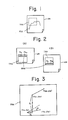
- Fig. 1 shows a graphic form or figure FIG. to be entered according to a graphic entering apparatus according to the present invention, the figure FIG being greater than the read-out area of a tablet input device in the graphic entering apparatus.
- Fig. 2 is explanatory of the principles behind the present invention.
- Fig. 2(A) shows a drawing positioned before it is displaced, and Fig. 2(B) the drawing located after it has been displaced.
- Designated in Fig. 2 at SRM is a special area indicated on the drawing for allowing the operator-to know how the drawing has been displaced. Prior to displacement of the drawing (Fig.
- Fig. 5 is a block diagram of a graphic entering apparatus according to the present invention.
- the apparatus includes a first register 101a for storing the coordinates (x01, y01) of a first specified point prior to displacement of the drawing, a second register 101 for storing the coordinates (x02, y02) of a second specified point prior to the drawing displacement, a third register 101 c for storing the coordinates (x11,y11) of the first specified point after the drawing has been displaced, and a fourth register 101d for storing the coordinates (x12, y12) of the second specified point subsequently to the drawing displacement.
- An NC data creating apparatus 104 employs the converted coordinates X', Y' to create NC data, which are then stored in a data memory 105. NC data are successively created and stored in the data memory 105 in this manner.
- the coordinate.s of the first and second specified points are set in the third and fourth registers 101c, 101d each time the drawing is displaced and the same coordinate transformation process as above is carried out.
- Fig. 6 is a perspective view of a system for creating NC data in which a graphics entering method and apparatus of the present invention are incorporated.
- the system includes the main body 11 of an apparatus for creating NC data.
- the main body 11 comprises a keyboard 11 a having a multiplicity of keys, a graphic display device 11 b, a magnetic tape cassette 11c, a printer 11d, and a control unit, not shown.
- the latter is equipped with a microcomputer which executes processing for the input and output of information, for digitizing and for the creation of NC data, all executed by means of the tablet described hereinbelow, based on a system program stored previously in memory means such as a ROM (read- only memory).
- the multiplicity of keys provided on the keyboard 11 a are used by the operator for instructing operations to be performed through conversational interaction, for designating system program loading, and for entering NC data.
- the graphic display device 11b displays, in graphical form, coordinate values obtained by digitization of positions designated by the tablet, as well as input, numerical values, NC data and various messages or prompts for conversational interaction with the operator.
- the magnetic tape cassette 11c is used to enter a system program into the main body of the NC data creating apparatus 11. By way of example, when using a tablet to enter coordinate values directly from a drawing and prepare NC data, the software (system program) for digitizing processing must be fed into the main body 11. This is done by loading the digitizing program from the magnetic tape cassette 11c into the main body 11.
- the printer 11 is adapted to print out characters which appear on the screen of the graphic display device 11 b, data punched in a paper tape, described later, and information which has been written into the loaded magnetic tape.
- the system also includes a paper tape reader/puncher 12 for preparing an NC tape by punching a paper tape with perforations indicative of the NC data prepared by the main body 11, and for reading NC or other data which has already been punched into an NC tape.
- the system tablet designated at 13, employs a ccordinate designating device such as a cursor unit or stylus pen as means for designating coordinates to input positional coordinates from a drawing laid on the tablet surface, these coordinates being fed into the main body 11 as an input thereto.
- the system tablet 13 corresponds to the tablet input device 102 shown in Fig. 5.
- Fig. 7 shows in perspective the tablet 13 in greater detail.
- the tablet 13 comprises a tablet main body or board 13b, a tablet cover 13a, a cursor unit 13c, a stylus pen 13d, a buzzer 13e, a group of lamps 13f indicating, e.g., coordinate input mode and introduction of power, an input/ output connector 13g for connecting the tablet 13 to the main body 11, a power unit 13h for supplying the tablet body 13b with D.C. power, an A.C. cable 13i, a D.C. cable 13j for connection between the tablet body and power unit, and a pen stand 13m for holding the stylus pen 13d when not in use.
- the cursor unit 13c or stylus pen 13d is used to enter coordinate and other data.
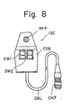
- the details of the cursor unit 13c are illustrated in the enlarged view of Fig. 8, in which a top view of the cursor unit is shown.
- the cursor unit 13c has a main body CSB, first and second switches SW1, SW2, a position reader RFP, a connector CNT and a cable CBL leading from the connector CNT to the main body CSB.
- first and second switches SW1, SW2 a position reader RFP
- a connector CNT a connector CNT
- a cable CBL leading from the connector CNT to the main body CSB.
- the present embodiment of the invention is highly advantageous in that the graphic form on a drawing can fully be entered even if the entire drawing overextends the tablet read-out area.
- the present embodiment of the invention is particularly suitable for use with an apparatus for creating NC data.
- a graphic form or figure drawn on a drawing and larger than the read-out area TRA of a tablet is divided into graphic patterns which are successively read by displacing the drawing.
- the extent to which the drawing is displaced is recognized, and graphic data read before and after the drawing is displaced is converted into data on one coordinate system and entered as inputs.
- two points Ps1, Ps2 are specified on the drawing, and the coordinates of the specified points prior (A) and subsequent (B) to displacement of the drawing are read and stored in first through fourth registers.
- the stored coordinates and the coordinates of points of the figure are entered into a coordinate transformation unit which effects arithmetic operations of coordinate transformation.
Landscapes
- Engineering & Computer Science (AREA)
- General Engineering & Computer Science (AREA)
- Theoretical Computer Science (AREA)
- Physics & Mathematics (AREA)
- General Physics & Mathematics (AREA)
- Human Computer Interaction (AREA)
- Automation & Control Theory (AREA)
- Processing Or Creating Images (AREA)
Applications Claiming Priority (2)
| Application Number | Priority Date | Filing Date | Title |
|---|---|---|---|
| JP57031495A JPS58149576A (ja) | 1982-02-27 | 1982-02-27 | 数置入力装置の図形入力装置 |
| JP31495/82 | 1982-02-27 |
Publications (2)
| Publication Number | Publication Date |
|---|---|
| EP0087944A1 EP0087944A1 (en) | 1983-09-07 |
| EP0087944B1 true EP0087944B1 (en) | 1987-12-02 |
Family
ID=12332822
Family Applications (1)
| Application Number | Title | Priority Date | Filing Date |
|---|---|---|---|
| EP83300999A Expired EP0087944B1 (en) | 1982-02-27 | 1983-02-25 | Method and apparatus for entering graphics |
Country Status (4)
| Country | Link |
|---|---|
| US (1) | US4555590A (enExample) |
| EP (1) | EP0087944B1 (enExample) |
| JP (1) | JPS58149576A (enExample) |
| DE (1) | DE3374816D1 (enExample) |
Families Citing this family (13)
| Publication number | Priority date | Publication date | Assignee | Title |
|---|---|---|---|---|
| DE3324951A1 (de) * | 1983-07-11 | 1985-01-24 | M.A.N.- Roland Druckmaschinen AG, 6050 Offenbach | Vorrichtung zum ermitteln und auswerten von farbmessfeldern auf einem auf einem messtisch liegenden druckbogen mit einem densitometer |
| US4737773A (en) * | 1984-09-04 | 1988-04-12 | Nec Corporation | Graphical display apparatus having a coordinate correction circuit |
| JPS6280723A (ja) * | 1985-10-04 | 1987-04-14 | Seiko Instr & Electronics Ltd | 読取メデイア保持装置付き座標読取装置 |
| US4697048A (en) * | 1986-04-29 | 1987-09-29 | Hewlett-Packard Company | Graphics tablet menu locator accommodating differing sizes of paper |
| JPS63136214A (ja) * | 1986-11-28 | 1988-06-08 | Pentel Kk | 座標入力装置 |
| US5162781A (en) * | 1987-10-02 | 1992-11-10 | Automated Decisions, Inc. | Orientational mouse computer input system |
| JP2683357B2 (ja) * | 1988-03-04 | 1997-11-26 | 理想科学工業株式会社 | データ入力装置 |
| JPH01290018A (ja) * | 1988-05-17 | 1989-11-21 | Wacom Co Ltd | 座標入力装置及び定点指定用位置指示器 |
| JPH0215304A (ja) * | 1988-07-04 | 1990-01-19 | Mitsubishi Electric Corp | 数値制御情報作成方法 |
| KR100324989B1 (ko) * | 1993-11-08 | 2002-06-24 | 마츠시타 덴끼 산교 가부시키가이샤 | 입력표시일체형정보처리장치 |
| US6259043B1 (en) | 1996-01-23 | 2001-07-10 | International Business Machines Corporation | Methods, systems and products pertaining to a digitizer for use in paper based record systems |
| US5983688A (en) * | 1996-07-08 | 1999-11-16 | Anzai; Tetsuya | Method and apparatus for displaying die layout in press brake and for checking interference |
| JP5617292B2 (ja) * | 2010-03-23 | 2014-11-05 | 富士通株式会社 | 送受信装置およびイメージング装置 |
Family Cites Families (4)
| Publication number | Priority date | Publication date | Assignee | Title |
|---|---|---|---|---|
| US3867616A (en) * | 1968-09-03 | 1975-02-18 | Badger Co | Automated designing |
| US4042866A (en) * | 1974-09-20 | 1977-08-16 | Daihatsu Motor Company, Limited | Method of preparing NC tapes |
| JPS5537664A (en) * | 1978-09-11 | 1980-03-15 | Hitachi Ltd | Conversational graphic processor |
| JPS5719809A (en) * | 1980-07-10 | 1982-02-02 | Fanuc Ltd | Numerical control information generating system |
-
1982
- 1982-02-27 JP JP57031495A patent/JPS58149576A/ja active Granted
-
1983
- 1983-02-25 US US06/469,824 patent/US4555590A/en not_active Expired - Fee Related
- 1983-02-25 EP EP83300999A patent/EP0087944B1/en not_active Expired
- 1983-02-25 DE DE8383300999T patent/DE3374816D1/de not_active Expired
Also Published As
| Publication number | Publication date |
|---|---|
| DE3374816D1 (en) | 1988-01-14 |
| JPH0143329B2 (enExample) | 1989-09-20 |
| EP0087944A1 (en) | 1983-09-07 |
| US4555590A (en) | 1985-11-26 |
| JPS58149576A (ja) | 1983-09-05 |
Similar Documents
| Publication | Publication Date | Title |
|---|---|---|
| EP0130219B1 (en) | Method of preparing part program | |
| EP0044192B1 (en) | A method for preparing numerical control information | |
| US4555590A (en) | Method and apparatus for entering graphics | |
| US4627003A (en) | Method and apparatus for creating numerical control data | |
| EP0087948B1 (en) | Method and apparatus for creating part program data | |
| EP0087945B1 (en) | Method and apparatus for setting coordinate system | |
| EP0079388B1 (en) | A numerical control method | |
| EP0089132A1 (en) | Method and apparatus for setting information input zone by coordinate input device | |
| EP0194316B1 (en) | Method of preparing nc data | |
| EP0088565A1 (en) | Method and apparatus for controlling entry of information by coordinate input device | |
| EP0087943B1 (en) | Method and apparatus for setting coordinate system origin | |
| EP0087949B1 (en) | Method and apparatus for creating numerical control data | |
| US5526273A (en) | Apparatus for monitoring and programming functioning of a machine for machining workpieces | |
| JP3148489B2 (ja) | 3次元対象物配置装置 | |
| EP0087947A2 (en) | Method and apparatus for correcting shapes | |
| JPS6249404A (ja) | Ncプログラムの編集方法および編集装置 | |
| JPH0675243B2 (ja) | 数値制御用マシンプログラム作成装置 | |
| JPS6046443B2 (ja) | 機能分散によるデ−タ入力制御方法 | |
| JP2943177B2 (ja) | 目盛数値付けxy座標軸の描画装置 | |
| JPH07113852B2 (ja) | 自動制御される作業機器の教示方法 | |
| JPS61105614A (ja) | Ncデ−タ作成装置における加工領域指定方式 | |
| JPH09156618A (ja) | 製造情報マーク出力装置 | |
| JPH0775037B2 (ja) | 画像回転指示方法 | |
| JPH0496110A (ja) | ティーチングデータ作成装置 | |
| JPS62247406A (ja) | 手書直接入力による数値制御装置 |
Legal Events
| Date | Code | Title | Description |
|---|---|---|---|
| PUAI | Public reference made under article 153(3) epc to a published international application that has entered the european phase |
Free format text: ORIGINAL CODE: 0009012 |
|
| AK | Designated contracting states |
Designated state(s): CH DE FR GB LI |
|
| 17P | Request for examination filed |
Effective date: 19840223 |
|
| GRAA | (expected) grant |
Free format text: ORIGINAL CODE: 0009210 |
|
| AK | Designated contracting states |
Kind code of ref document: B1 Designated state(s): CH DE FR GB LI |
|
| REF | Corresponds to: |
Ref document number: 3374816 Country of ref document: DE Date of ref document: 19880114 |
|
| ET | Fr: translation filed | ||
| PLBE | No opposition filed within time limit |
Free format text: ORIGINAL CODE: 0009261 |
|
| STAA | Information on the status of an ep patent application or granted ep patent |
Free format text: STATUS: NO OPPOSITION FILED WITHIN TIME LIMIT |
|
| 26N | No opposition filed | ||
| PGFP | Annual fee paid to national office [announced via postgrant information from national office to epo] |
Ref country code: FR Payment date: 19910207 Year of fee payment: 9 |
|
| PGFP | Annual fee paid to national office [announced via postgrant information from national office to epo] |
Ref country code: GB Payment date: 19910212 Year of fee payment: 9 |
|
| PG25 | Lapsed in a contracting state [announced via postgrant information from national office to epo] |
Ref country code: GB Effective date: 19920225 |
|
| GBPC | Gb: european patent ceased through non-payment of renewal fee | ||
| PG25 | Lapsed in a contracting state [announced via postgrant information from national office to epo] |
Ref country code: FR Effective date: 19921030 |
|
| REG | Reference to a national code |
Ref country code: FR Ref legal event code: ST |
|
| PGFP | Annual fee paid to national office [announced via postgrant information from national office to epo] |
Ref country code: DE Payment date: 19960227 Year of fee payment: 14 |
|
| PGFP | Annual fee paid to national office [announced via postgrant information from national office to epo] |
Ref country code: CH Payment date: 19960315 Year of fee payment: 14 |
|
| PG25 | Lapsed in a contracting state [announced via postgrant information from national office to epo] |
Ref country code: LI Effective date: 19970228 Ref country code: CH Effective date: 19970228 |
|
| REG | Reference to a national code |
Ref country code: CH Ref legal event code: PL |
|
| PG25 | Lapsed in a contracting state [announced via postgrant information from national office to epo] |
Ref country code: DE Effective date: 19971101 |