EP0087613A1 - Verfahren und Vorrichtung zum Herstellen mehrschichtiger Isolierrohre aus Schaumstoffstreifen - Google Patents
Verfahren und Vorrichtung zum Herstellen mehrschichtiger Isolierrohre aus Schaumstoffstreifen Download PDFInfo
- Publication number
- EP0087613A1 EP0087613A1 EP83101086A EP83101086A EP0087613A1 EP 0087613 A1 EP0087613 A1 EP 0087613A1 EP 83101086 A EP83101086 A EP 83101086A EP 83101086 A EP83101086 A EP 83101086A EP 0087613 A1 EP0087613 A1 EP 0087613A1
- Authority
- EP
- European Patent Office
- Prior art keywords
- layer
- foam
- wrapping
- layers
- strips
- Prior art date
- Legal status (The legal status is an assumption and is not a legal conclusion. Google has not performed a legal analysis and makes no representation as to the accuracy of the status listed.)
- Granted
Links
Images


Classifications
-
- F—MECHANICAL ENGINEERING; LIGHTING; HEATING; WEAPONS; BLASTING
- F16—ENGINEERING ELEMENTS AND UNITS; GENERAL MEASURES FOR PRODUCING AND MAINTAINING EFFECTIVE FUNCTIONING OF MACHINES OR INSTALLATIONS; THERMAL INSULATION IN GENERAL
- F16L—PIPES; JOINTS OR FITTINGS FOR PIPES; SUPPORTS FOR PIPES, CABLES OR PROTECTIVE TUBING; MEANS FOR THERMAL INSULATION IN GENERAL
- F16L59/00—Thermal insulation in general
- F16L59/02—Shape or form of insulating materials, with or without coverings integral with the insulating materials
- F16L59/029—Shape or form of insulating materials, with or without coverings integral with the insulating materials layered
-
- B—PERFORMING OPERATIONS; TRANSPORTING
- B29—WORKING OF PLASTICS; WORKING OF SUBSTANCES IN A PLASTIC STATE IN GENERAL
- B29C—SHAPING OR JOINING OF PLASTICS; SHAPING OF MATERIAL IN A PLASTIC STATE, NOT OTHERWISE PROVIDED FOR; AFTER-TREATMENT OF THE SHAPED PRODUCTS, e.g. REPAIRING
- B29C53/00—Shaping by bending, folding, twisting, straightening or flattening; Apparatus therefor
- B29C53/36—Bending and joining, e.g. for making hollow articles
-
- B—PERFORMING OPERATIONS; TRANSPORTING
- B29—WORKING OF PLASTICS; WORKING OF SUBSTANCES IN A PLASTIC STATE IN GENERAL
- B29C—SHAPING OR JOINING OF PLASTICS; SHAPING OF MATERIAL IN A PLASTIC STATE, NOT OTHERWISE PROVIDED FOR; AFTER-TREATMENT OF THE SHAPED PRODUCTS, e.g. REPAIRING
- B29C65/00—Joining or sealing of preformed parts, e.g. welding of plastics materials; Apparatus therefor
- B29C65/78—Means for handling the parts to be joined, e.g. for making containers or hollow articles, e.g. means for handling sheets, plates, web-like materials, tubular articles, hollow articles or elements to be joined therewith; Means for discharging the joined articles from the joining apparatus
-
- B—PERFORMING OPERATIONS; TRANSPORTING
- B29—WORKING OF PLASTICS; WORKING OF SUBSTANCES IN A PLASTIC STATE IN GENERAL
- B29C—SHAPING OR JOINING OF PLASTICS; SHAPING OF MATERIAL IN A PLASTIC STATE, NOT OTHERWISE PROVIDED FOR; AFTER-TREATMENT OF THE SHAPED PRODUCTS, e.g. REPAIRING
- B29C66/00—General aspects of processes or apparatus for joining preformed parts
- B29C66/01—General aspects dealing with the joint area or with the area to be joined
- B29C66/05—Particular design of joint configurations
- B29C66/10—Particular design of joint configurations particular design of the joint cross-sections
- B29C66/11—Joint cross-sections comprising a single joint-segment, i.e. one of the parts to be joined comprising a single joint-segment in the joint cross-section
- B29C66/112—Single lapped joints
- B29C66/1122—Single lap to lap joints, i.e. overlap joints
-
- B—PERFORMING OPERATIONS; TRANSPORTING
- B29—WORKING OF PLASTICS; WORKING OF SUBSTANCES IN A PLASTIC STATE IN GENERAL
- B29C—SHAPING OR JOINING OF PLASTICS; SHAPING OF MATERIAL IN A PLASTIC STATE, NOT OTHERWISE PROVIDED FOR; AFTER-TREATMENT OF THE SHAPED PRODUCTS, e.g. REPAIRING
- B29C66/00—General aspects of processes or apparatus for joining preformed parts
- B29C66/01—General aspects dealing with the joint area or with the area to be joined
- B29C66/05—Particular design of joint configurations
- B29C66/10—Particular design of joint configurations particular design of the joint cross-sections
- B29C66/11—Joint cross-sections comprising a single joint-segment, i.e. one of the parts to be joined comprising a single joint-segment in the joint cross-section
- B29C66/114—Single butt joints
- B29C66/1142—Single butt to butt joints
-
- B—PERFORMING OPERATIONS; TRANSPORTING
- B29—WORKING OF PLASTICS; WORKING OF SUBSTANCES IN A PLASTIC STATE IN GENERAL
- B29C—SHAPING OR JOINING OF PLASTICS; SHAPING OF MATERIAL IN A PLASTIC STATE, NOT OTHERWISE PROVIDED FOR; AFTER-TREATMENT OF THE SHAPED PRODUCTS, e.g. REPAIRING
- B29C66/00—General aspects of processes or apparatus for joining preformed parts
- B29C66/01—General aspects dealing with the joint area or with the area to be joined
- B29C66/05—Particular design of joint configurations
- B29C66/10—Particular design of joint configurations particular design of the joint cross-sections
- B29C66/11—Joint cross-sections comprising a single joint-segment, i.e. one of the parts to be joined comprising a single joint-segment in the joint cross-section
- B29C66/116—Single bevelled joints, i.e. one of the parts to be joined being bevelled in the joint area
- B29C66/1162—Single bevel to bevel joints, e.g. mitre joints
-
- B—PERFORMING OPERATIONS; TRANSPORTING
- B29—WORKING OF PLASTICS; WORKING OF SUBSTANCES IN A PLASTIC STATE IN GENERAL
- B29C—SHAPING OR JOINING OF PLASTICS; SHAPING OF MATERIAL IN A PLASTIC STATE, NOT OTHERWISE PROVIDED FOR; AFTER-TREATMENT OF THE SHAPED PRODUCTS, e.g. REPAIRING
- B29C66/00—General aspects of processes or apparatus for joining preformed parts
- B29C66/01—General aspects dealing with the joint area or with the area to be joined
- B29C66/05—Particular design of joint configurations
- B29C66/10—Particular design of joint configurations particular design of the joint cross-sections
- B29C66/12—Joint cross-sections combining only two joint-segments; Tongue and groove joints; Tenon and mortise joints; Stepped joint cross-sections
- B29C66/124—Tongue and groove joints
- B29C66/1246—Tongue and groove joints characterised by the female part, i.e. the part comprising the groove
- B29C66/12463—Tongue and groove joints characterised by the female part, i.e. the part comprising the groove being tapered
- B29C66/12464—Tongue and groove joints characterised by the female part, i.e. the part comprising the groove being tapered being V-shaped
-
- B—PERFORMING OPERATIONS; TRANSPORTING
- B29—WORKING OF PLASTICS; WORKING OF SUBSTANCES IN A PLASTIC STATE IN GENERAL
- B29C—SHAPING OR JOINING OF PLASTICS; SHAPING OF MATERIAL IN A PLASTIC STATE, NOT OTHERWISE PROVIDED FOR; AFTER-TREATMENT OF THE SHAPED PRODUCTS, e.g. REPAIRING
- B29C66/00—General aspects of processes or apparatus for joining preformed parts
- B29C66/01—General aspects dealing with the joint area or with the area to be joined
- B29C66/05—Particular design of joint configurations
- B29C66/10—Particular design of joint configurations particular design of the joint cross-sections
- B29C66/12—Joint cross-sections combining only two joint-segments; Tongue and groove joints; Tenon and mortise joints; Stepped joint cross-sections
- B29C66/128—Stepped joint cross-sections
- B29C66/1282—Stepped joint cross-sections comprising at least one overlap joint-segment
-
- B—PERFORMING OPERATIONS; TRANSPORTING
- B29—WORKING OF PLASTICS; WORKING OF SUBSTANCES IN A PLASTIC STATE IN GENERAL
- B29C—SHAPING OR JOINING OF PLASTICS; SHAPING OF MATERIAL IN A PLASTIC STATE, NOT OTHERWISE PROVIDED FOR; AFTER-TREATMENT OF THE SHAPED PRODUCTS, e.g. REPAIRING
- B29C66/00—General aspects of processes or apparatus for joining preformed parts
- B29C66/01—General aspects dealing with the joint area or with the area to be joined
- B29C66/05—Particular design of joint configurations
- B29C66/10—Particular design of joint configurations particular design of the joint cross-sections
- B29C66/12—Joint cross-sections combining only two joint-segments; Tongue and groove joints; Tenon and mortise joints; Stepped joint cross-sections
- B29C66/128—Stepped joint cross-sections
- B29C66/1284—Stepped joint cross-sections comprising at least one butt joint-segment
- B29C66/12841—Stepped joint cross-sections comprising at least one butt joint-segment comprising at least two butt joint-segments
-
- B—PERFORMING OPERATIONS; TRANSPORTING
- B29—WORKING OF PLASTICS; WORKING OF SUBSTANCES IN A PLASTIC STATE IN GENERAL
- B29C—SHAPING OR JOINING OF PLASTICS; SHAPING OF MATERIAL IN A PLASTIC STATE, NOT OTHERWISE PROVIDED FOR; AFTER-TREATMENT OF THE SHAPED PRODUCTS, e.g. REPAIRING
- B29C66/00—General aspects of processes or apparatus for joining preformed parts
- B29C66/01—General aspects dealing with the joint area or with the area to be joined
- B29C66/05—Particular design of joint configurations
- B29C66/303—Particular design of joint configurations the joint involving an anchoring effect
- B29C66/3032—Particular design of joint configurations the joint involving an anchoring effect making use of protusions or cavities belonging to at least one of the parts to be joined
- B29C66/30321—Particular design of joint configurations the joint involving an anchoring effect making use of protusions or cavities belonging to at least one of the parts to be joined making use of protusions belonging to at least one of the parts to be joined
-
- B—PERFORMING OPERATIONS; TRANSPORTING
- B29—WORKING OF PLASTICS; WORKING OF SUBSTANCES IN A PLASTIC STATE IN GENERAL
- B29C—SHAPING OR JOINING OF PLASTICS; SHAPING OF MATERIAL IN A PLASTIC STATE, NOT OTHERWISE PROVIDED FOR; AFTER-TREATMENT OF THE SHAPED PRODUCTS, e.g. REPAIRING
- B29C66/00—General aspects of processes or apparatus for joining preformed parts
- B29C66/01—General aspects dealing with the joint area or with the area to be joined
- B29C66/05—Particular design of joint configurations
- B29C66/303—Particular design of joint configurations the joint involving an anchoring effect
- B29C66/3032—Particular design of joint configurations the joint involving an anchoring effect making use of protusions or cavities belonging to at least one of the parts to be joined
- B29C66/30325—Particular design of joint configurations the joint involving an anchoring effect making use of protusions or cavities belonging to at least one of the parts to be joined making use of cavities belonging to at least one of the parts to be joined
-
- B—PERFORMING OPERATIONS; TRANSPORTING
- B29—WORKING OF PLASTICS; WORKING OF SUBSTANCES IN A PLASTIC STATE IN GENERAL
- B29C—SHAPING OR JOINING OF PLASTICS; SHAPING OF MATERIAL IN A PLASTIC STATE, NOT OTHERWISE PROVIDED FOR; AFTER-TREATMENT OF THE SHAPED PRODUCTS, e.g. REPAIRING
- B29C66/00—General aspects of processes or apparatus for joining preformed parts
- B29C66/40—General aspects of joining substantially flat articles, e.g. plates, sheets or web-like materials; Making flat seams in tubular or hollow articles; Joining single elements to substantially flat surfaces
- B29C66/41—Joining substantially flat articles ; Making flat seams in tubular or hollow articles
- B29C66/43—Joining a relatively small portion of the surface of said articles
- B29C66/432—Joining a relatively small portion of the surface of said articles for making tubular articles or closed loops, e.g. by joining several sheets ; for making hollow articles or hollow preforms
- B29C66/4322—Joining a relatively small portion of the surface of said articles for making tubular articles or closed loops, e.g. by joining several sheets ; for making hollow articles or hollow preforms by joining a single sheet to itself
-
- B—PERFORMING OPERATIONS; TRANSPORTING
- B29—WORKING OF PLASTICS; WORKING OF SUBSTANCES IN A PLASTIC STATE IN GENERAL
- B29C—SHAPING OR JOINING OF PLASTICS; SHAPING OF MATERIAL IN A PLASTIC STATE, NOT OTHERWISE PROVIDED FOR; AFTER-TREATMENT OF THE SHAPED PRODUCTS, e.g. REPAIRING
- B29C66/00—General aspects of processes or apparatus for joining preformed parts
- B29C66/40—General aspects of joining substantially flat articles, e.g. plates, sheets or web-like materials; Making flat seams in tubular or hollow articles; Joining single elements to substantially flat surfaces
- B29C66/49—Internally supporting the, e.g. tubular, article during joining
-
- B—PERFORMING OPERATIONS; TRANSPORTING
- B29—WORKING OF PLASTICS; WORKING OF SUBSTANCES IN A PLASTIC STATE IN GENERAL
- B29C—SHAPING OR JOINING OF PLASTICS; SHAPING OF MATERIAL IN A PLASTIC STATE, NOT OTHERWISE PROVIDED FOR; AFTER-TREATMENT OF THE SHAPED PRODUCTS, e.g. REPAIRING
- B29C66/00—General aspects of processes or apparatus for joining preformed parts
- B29C66/50—General aspects of joining tubular articles; General aspects of joining long products, i.e. bars or profiled elements; General aspects of joining single elements to tubular articles, hollow articles or bars; General aspects of joining several hollow-preforms to form hollow or tubular articles
- B29C66/51—Joining tubular articles, profiled elements or bars; Joining single elements to tubular articles, hollow articles or bars; Joining several hollow-preforms to form hollow or tubular articles
- B29C66/53—Joining single elements to tubular articles, hollow articles or bars
- B29C66/532—Joining single elements to the wall of tubular articles, hollow articles or bars
- B29C66/5326—Joining single elements to the wall of tubular articles, hollow articles or bars said single elements being substantially flat
-
- B—PERFORMING OPERATIONS; TRANSPORTING
- B29—WORKING OF PLASTICS; WORKING OF SUBSTANCES IN A PLASTIC STATE IN GENERAL
- B29C—SHAPING OR JOINING OF PLASTICS; SHAPING OF MATERIAL IN A PLASTIC STATE, NOT OTHERWISE PROVIDED FOR; AFTER-TREATMENT OF THE SHAPED PRODUCTS, e.g. REPAIRING
- B29C66/00—General aspects of processes or apparatus for joining preformed parts
- B29C66/70—General aspects of processes or apparatus for joining preformed parts characterised by the composition, physical properties or the structure of the material of the parts to be joined; Joining with non-plastics material
- B29C66/72—General aspects of processes or apparatus for joining preformed parts characterised by the composition, physical properties or the structure of the material of the parts to be joined; Joining with non-plastics material characterised by the structure of the material of the parts to be joined
- B29C66/723—General aspects of processes or apparatus for joining preformed parts characterised by the composition, physical properties or the structure of the material of the parts to be joined; Joining with non-plastics material characterised by the structure of the material of the parts to be joined being multi-layered
-
- B—PERFORMING OPERATIONS; TRANSPORTING
- B29—WORKING OF PLASTICS; WORKING OF SUBSTANCES IN A PLASTIC STATE IN GENERAL
- B29C—SHAPING OR JOINING OF PLASTICS; SHAPING OF MATERIAL IN A PLASTIC STATE, NOT OTHERWISE PROVIDED FOR; AFTER-TREATMENT OF THE SHAPED PRODUCTS, e.g. REPAIRING
- B29C66/00—General aspects of processes or apparatus for joining preformed parts
- B29C66/70—General aspects of processes or apparatus for joining preformed parts characterised by the composition, physical properties or the structure of the material of the parts to be joined; Joining with non-plastics material
- B29C66/72—General aspects of processes or apparatus for joining preformed parts characterised by the composition, physical properties or the structure of the material of the parts to be joined; Joining with non-plastics material characterised by the structure of the material of the parts to be joined
- B29C66/727—General aspects of processes or apparatus for joining preformed parts characterised by the composition, physical properties or the structure of the material of the parts to be joined; Joining with non-plastics material characterised by the structure of the material of the parts to be joined being porous, e.g. foam
-
- B—PERFORMING OPERATIONS; TRANSPORTING
- B29—WORKING OF PLASTICS; WORKING OF SUBSTANCES IN A PLASTIC STATE IN GENERAL
- B29C—SHAPING OR JOINING OF PLASTICS; SHAPING OF MATERIAL IN A PLASTIC STATE, NOT OTHERWISE PROVIDED FOR; AFTER-TREATMENT OF THE SHAPED PRODUCTS, e.g. REPAIRING
- B29C66/00—General aspects of processes or apparatus for joining preformed parts
- B29C66/01—General aspects dealing with the joint area or with the area to be joined
- B29C66/05—Particular design of joint configurations
- B29C66/10—Particular design of joint configurations particular design of the joint cross-sections
- B29C66/12—Joint cross-sections combining only two joint-segments; Tongue and groove joints; Tenon and mortise joints; Stepped joint cross-sections
- B29C66/122—Joint cross-sections combining only two joint-segments, i.e. one of the parts to be joined comprising only two joint-segments in the joint cross-section
- B29C66/1226—Joint cross-sections combining only two joint-segments, i.e. one of the parts to be joined comprising only two joint-segments in the joint cross-section comprising at least one bevelled joint-segment
- B29C66/12261—Joint cross-sections combining only two joint-segments, i.e. one of the parts to be joined comprising only two joint-segments in the joint cross-section comprising at least one bevelled joint-segment the two joint-segments being bevelled, e.g. the two joint-segments forming a V
-
- B—PERFORMING OPERATIONS; TRANSPORTING
- B29—WORKING OF PLASTICS; WORKING OF SUBSTANCES IN A PLASTIC STATE IN GENERAL
- B29C—SHAPING OR JOINING OF PLASTICS; SHAPING OF MATERIAL IN A PLASTIC STATE, NOT OTHERWISE PROVIDED FOR; AFTER-TREATMENT OF THE SHAPED PRODUCTS, e.g. REPAIRING
- B29C66/00—General aspects of processes or apparatus for joining preformed parts
- B29C66/40—General aspects of joining substantially flat articles, e.g. plates, sheets or web-like materials; Making flat seams in tubular or hollow articles; Joining single elements to substantially flat surfaces
- B29C66/49—Internally supporting the, e.g. tubular, article during joining
- B29C66/496—Internally supporting the, e.g. tubular, article during joining using a support which remains in the joined object
-
- B—PERFORMING OPERATIONS; TRANSPORTING
- B29—WORKING OF PLASTICS; WORKING OF SUBSTANCES IN A PLASTIC STATE IN GENERAL
- B29C—SHAPING OR JOINING OF PLASTICS; SHAPING OF MATERIAL IN A PLASTIC STATE, NOT OTHERWISE PROVIDED FOR; AFTER-TREATMENT OF THE SHAPED PRODUCTS, e.g. REPAIRING
- B29C66/00—General aspects of processes or apparatus for joining preformed parts
- B29C66/70—General aspects of processes or apparatus for joining preformed parts characterised by the composition, physical properties or the structure of the material of the parts to be joined; Joining with non-plastics material
- B29C66/71—General aspects of processes or apparatus for joining preformed parts characterised by the composition, physical properties or the structure of the material of the parts to be joined; Joining with non-plastics material characterised by the composition of the plastics material of the parts to be joined
-
- B—PERFORMING OPERATIONS; TRANSPORTING
- B29—WORKING OF PLASTICS; WORKING OF SUBSTANCES IN A PLASTIC STATE IN GENERAL
- B29C—SHAPING OR JOINING OF PLASTICS; SHAPING OF MATERIAL IN A PLASTIC STATE, NOT OTHERWISE PROVIDED FOR; AFTER-TREATMENT OF THE SHAPED PRODUCTS, e.g. REPAIRING
- B29C66/00—General aspects of processes or apparatus for joining preformed parts
- B29C66/70—General aspects of processes or apparatus for joining preformed parts characterised by the composition, physical properties or the structure of the material of the parts to be joined; Joining with non-plastics material
- B29C66/72—General aspects of processes or apparatus for joining preformed parts characterised by the composition, physical properties or the structure of the material of the parts to be joined; Joining with non-plastics material characterised by the structure of the material of the parts to be joined
- B29C66/723—General aspects of processes or apparatus for joining preformed parts characterised by the composition, physical properties or the structure of the material of the parts to be joined; Joining with non-plastics material characterised by the structure of the material of the parts to be joined being multi-layered
- B29C66/7232—General aspects of processes or apparatus for joining preformed parts characterised by the composition, physical properties or the structure of the material of the parts to be joined; Joining with non-plastics material characterised by the structure of the material of the parts to be joined being multi-layered comprising a non-plastics layer
- B29C66/72321—General aspects of processes or apparatus for joining preformed parts characterised by the composition, physical properties or the structure of the material of the parts to be joined; Joining with non-plastics material characterised by the structure of the material of the parts to be joined being multi-layered comprising a non-plastics layer consisting of metals or their alloys
-
- B—PERFORMING OPERATIONS; TRANSPORTING
- B29—WORKING OF PLASTICS; WORKING OF SUBSTANCES IN A PLASTIC STATE IN GENERAL
- B29C—SHAPING OR JOINING OF PLASTICS; SHAPING OF MATERIAL IN A PLASTIC STATE, NOT OTHERWISE PROVIDED FOR; AFTER-TREATMENT OF THE SHAPED PRODUCTS, e.g. REPAIRING
- B29C66/00—General aspects of processes or apparatus for joining preformed parts
- B29C66/70—General aspects of processes or apparatus for joining preformed parts characterised by the composition, physical properties or the structure of the material of the parts to be joined; Joining with non-plastics material
- B29C66/72—General aspects of processes or apparatus for joining preformed parts characterised by the composition, physical properties or the structure of the material of the parts to be joined; Joining with non-plastics material characterised by the structure of the material of the parts to be joined
- B29C66/723—General aspects of processes or apparatus for joining preformed parts characterised by the composition, physical properties or the structure of the material of the parts to be joined; Joining with non-plastics material characterised by the structure of the material of the parts to be joined being multi-layered
- B29C66/7234—General aspects of processes or apparatus for joining preformed parts characterised by the composition, physical properties or the structure of the material of the parts to be joined; Joining with non-plastics material characterised by the structure of the material of the parts to be joined being multi-layered comprising a barrier layer
- B29C66/72341—General aspects of processes or apparatus for joining preformed parts characterised by the composition, physical properties or the structure of the material of the parts to be joined; Joining with non-plastics material characterised by the structure of the material of the parts to be joined being multi-layered comprising a barrier layer for gases
-
- B—PERFORMING OPERATIONS; TRANSPORTING
- B29—WORKING OF PLASTICS; WORKING OF SUBSTANCES IN A PLASTIC STATE IN GENERAL
- B29K—INDEXING SCHEME ASSOCIATED WITH SUBCLASSES B29B, B29C OR B29D, RELATING TO MOULDING MATERIALS OR TO MATERIALS FOR MOULDS, REINFORCEMENTS, FILLERS OR PREFORMED PARTS, e.g. INSERTS
- B29K2105/00—Condition, form or state of moulded material or of the material to be shaped
- B29K2105/04—Condition, form or state of moulded material or of the material to be shaped cellular or porous
-
- B—PERFORMING OPERATIONS; TRANSPORTING
- B29—WORKING OF PLASTICS; WORKING OF SUBSTANCES IN A PLASTIC STATE IN GENERAL
- B29L—INDEXING SCHEME ASSOCIATED WITH SUBCLASS B29C, RELATING TO PARTICULAR ARTICLES
- B29L2009/00—Layered products
-
- B—PERFORMING OPERATIONS; TRANSPORTING
- B29—WORKING OF PLASTICS; WORKING OF SUBSTANCES IN A PLASTIC STATE IN GENERAL
- B29L—INDEXING SCHEME ASSOCIATED WITH SUBCLASS B29C, RELATING TO PARTICULAR ARTICLES
- B29L2023/00—Tubular articles
- B29L2023/22—Tubes or pipes, i.e. rigid
- B29L2023/225—Insulated
Definitions
- the subject matter of the invention relates to a method for producing multilayer insulating tubes from a plurality of covering layers of foam strips, in particular the side which later forms the inside of the insulating tube is briefly warmed up to the thermoelastic or thermoplastic state and then the foam strip is deformed transversely to its longitudinal extent to form the tube cross section and lengthways the side edges are connected and multilayer insulating pipes produced according to this.
- the invention is concerned with a device for carrying out the method with a circulating belt for transporting the continuously running foam strips, a heating device, a form funnel with a cooled molded tube and a device for closing the butt seam of the side edges.
- Pipe insulation made of foam plastics can, insofar as they originate from foam sheets or strips, for example by deforming strips into a tube shape and then closing the butt joint running in the longitudinal direction by welding, gluing or the like. are produced (DE-AS 25 03 382 and DE-AS 25 32 406). Such manufacturing processes require complex machines and molds. The necessary thickness of the insulation requires heat treatment because of the tendency of the foams to reset, with the risk of damaging the foams. The considerable thickness of the insulating layer, especially of pipes of larger width, can only be achieved with complex measures. Multi-layer pipe insulation can be produced, for example according to DE-OS 19 15 768, by wrapping or crosswise winding in several layers.
- the pipe diameters to be insulated are predominantly smaller than 45 mm, the required insulation thickness corresponds approximately to a pipe diameter.
- a pipe diameter of 30 mm for example, this means that an insulation pipe made of foam with a thickness of 30 mm has an inner diameter of approximately 30 mm and an outer diameter of 90 mm. It is very difficult to form an insulating tube with such small inner diameters from thick foam strips without avoiding compression and wrinkling of the foam.
- Another object of the invention is to produce thick-walled insulating pipes in a continuous process by means of heating, avoiding wrinkles and in particular for smaller pipe diameters, as are customary in installation insulation.
- the invention is based on multilayer, thick-walled insulating tubes which are constructed from a plurality of foam strips arranged one above the other.
- a method for producing multilayer insulating tubes from a plurality of covering layers made of foam plastics in which a multilayer arrangement of covering layers in a planar extent and. predetermined length and different width, which corresponds to the pipe circumference or the pipe circumference increased by the respectively applied thickness of the sheathing layer, the individual sheathing layers of which are arranged offset in the pipe circumferential direction from the adjacent sheathing layer, and each sheathing layer in the direction of the pipe longitudinal axis with the neighboring sheathing layer partially, as a line, is connected, then the multilayer arrangement is formed into an insulating tube, the front edges of each wrapping layer closing to form a closed casing and at least the butt joint formed in the outermost wrapping layer being closed on the outside and / or in the butt joint.
- the sheathing layers Due to the only linear or small width connection of the sheathing layers, the sheathing layers remain displaceable perpendicular to the connection in the circumferential direction of the pipe and are therefore easily adaptable to the pipe circumference and can thus be easily formed from the planar extent for pipe insulation.
- the pipe insulation is produced on the basis of the planar, preferably prefabricated, arrangement of several foam layers by bending to the pipe shape on the pipe itself until the end edges of each casing layer touch and then closing the butt joint running in the direction of the pipe longitudinal axis, at least the outermost casing layer.
- the pipe insulation can be produced at the place where the pipes are laid. Even long pipes or pipe sections and pipes with large diameters or pipe bundles can be installed on site using simple aids, e.g. Channels or boxes, but also without aids, are covered with the pipe insulation.
- the application of the arrangement of several foam layers and the deformation to the sheathing is made considerably easier by fixing the innermost sheathing layer to the pipe, which is achieved by gluing with e.g.
- an adhesive or through a narrow adhesive strip under the innermost wrapping layer preferably close to the beginning, over the length of the tube.
- An adhesive tape or double-sided adhesive tape is expediently already attached to the lowermost side of the lowermost wrapping layer, the protective layer of which can be removed.
- the wrapping process begins by fixing the underside of the innermost wrapping layer on the pipe parallel to the pipe longitudinal axis, provided that a fixation is provided in the preferred case. Then, in the case of a stepped, beveled or offset butt joint, the profile of the end edge of the butt joint last applied in the wrapping direction should overlap at the top. Likewise, a closure that may have been placed on the outermost wrapping layer should lie above the last edge applied in the wrapping direction.
- the width of each wrapping layer should be such that the shortest wrapping layer as the innermost and each subsequent layer adapt to the respective circumference and the butt joints close with the wrapping.
- the wrapping layers compress on the underside and stretch above a bending line lying approximately in the middle of the layer thickness, the mean thickness of each web (taking into account the cutting line of the butt joint) has the length of the development as intended Bend line to match.
- each layer is of comparatively small thickness, which, depending on the rigidity of the foam plastics used and the pipe diameter, is at most one or a few cm, preferably 5 to 20 mm.
- Another important factor is e.g. linear connection parallel to the pipe longitudinal axis of the wrapping layers with the adjacent layer and the otherwise free displacement of the wrapping layers against each other on their other contact surface for the easy execution of the progressive wrapping process.
- the individual wrapping layers can consist of the same or different foam plastics, of the same or different thickness.
- the preferred material is cross-linked or possibly non-cross-linked polyethylene foam.
- innermost cladding layer to be thinner than the following and possibly formed from more flexible foams than the following, which are bent less closely in the wrapping process.
- the innermost as well as the outermost layer can consist of another flat material.
- Such flat materials include Metal foils such as Aluminum foils or plastic foils.
- These layers can also be coated with the innermost or outermost cladding layer by e.g. Laminate or glue connected. They serve a wide variety of tasks, e.g. as a vapor barrier or mechanical protection, for coloring ,. as protection against inflammation or against weather influences. Furthermore, the sintering of the surface of the outermost layer against mechanical stress has proven itself.
- the production of the multilayer pipe insulation is particularly simple and therefore very preferred when using a prefabricated multilayer arrangement of wrapping layers made of foam plastics in a planar extension, the individual wrapping layers of which already have the format for wrapping pipes of certain sizes and, if appropriate, certain lengths, and expediently already have the linear form mentioned Having connection to the adjacent layer
- Several such arrangements of enveloping layers in a planar extent can be applied to a pipe, independently or in succession.
- Another object of the invention is therefore a multilayer arrangement of wrapping layers made of foam plastics in a planar extent for the pipe insulation of pipes made of metals, plastics, ceramics or the like. of different widths of the respective cladding layers, that of the pipe circumference or that to be applied beforehand
- the corresponding thickness of the cladding layer corresponds to the enlarged pipe circumference, the individual cladding layers of which are arranged offset in the pipe circumferential direction from the neighboring cladding layer and in which the cladding layers are connected in the least linear manner in the direction of the pipe longitudinal axis with the neighboring cladding layer.
- connection of the wrapping layers in the arrangement is particularly advantageous and essential because of the only narrow connection in the direction of the later pipe longitudinal axis, since the wrapping layers belonging to one another are available ready for assembly with the appropriate width and suitable displacement for the respective pipe circumference.
- the prefabricated flat arrangement of foam layers can simply be packaged and shipped as a flat layer of several foam webs or strips.
- the starting material for the arrangement are standard plastic foam sheets.
- sheathing layers of the intended length are cut from foam sheets, the width of the innermost layer in the sheathing corresponding to the tube circumference, and each subsequent layer having a greater width, which results from the circumference of the sheathing from the preceding one Location results.
- These wrapping layers are offset from one another, preferably stacked on top of one another, so that each subsequent wrapping layer is wider than the previous one.
- the displacement need only be slight, but expediently more than one layer thickness, ie one or a few cm, can also be more.
- each wrapping layer is or the like with the neighboring one on a small width by gluing, welding, sewing. connected.
- These connections can be continuous or intermittent as point or route stapling.
- the supply connections 5 are arranged in a preferred embodiment close to the displacement. That makes wrapping easier, insofar as the wrapping process preferably begins at the offset, since the wrapping layers remain movable relative to one another as the wrapping progresses in the direction of rotation.
- a fixation to be attached to the pipe is preferably provided on the flat arrangement under the innermost wrapping layer.
- a fixation at the beginning of the lowest layer near the transfer is advisable as long as the wrapping process begins there.
- the fixation is preferably carried out with an adhesive tape running parallel to the tube axis with a removable protective layer, which is preferably already attached to the prefabricated arrangement.
- the fixation can also be carried out using adhesives which can be activated with heat or solvents.
- the uppermost, later outer covering layer of the planar arrangement preferably already carries a closure system for the uppermost butt joint in the direction of the pipe longitudinal axis in the prefabricated state, for example a slide fastener, pull fastener, Velcro fastener or the like.
- the closure can also by welding, gluing or the like. or by attaching one of the closures mentioned after deforming the arrangement for the sheathing.
- the contact surface of the later butt joint formed by the two front edges of each cladding layer can have different shapes.
- the wrapping layer is cut vertically, whereby both front edges form a radial butt joint after wrapping. When the cut is made obliquely to the spreading of the wrapping layer, front edges of the wrapping layer result which overlap. Cuts that are not flat result in particularly large contact surfaces which facilitate the wrapping.
- the fixation to be attached to the pipe and also the connection of the covering layer are arranged close to or in the region of the offset and consequently the covering process begins there, the last front edge placed is preferred in the case of a stepped, beveled or profiled design of the end edges designed so that the top of the end edge overlaps in the wrapping direction.
- the displacement of each wrapping layer with respect to the next is small, i.e. is a few centimeters.
- the connections are preferably also close to the dislocation or near the end edges of the respective upper wrapping layer.
- An existing fixation lies under the innermost wrapping layer close to the front edge.
- This case shown in FIG. 1 leads to plan arrangements of the smallest overall width and maximum displaceability of the individual sheathing layers in the direction of the pipe circumference.
- Another case is that with a maximum width of the dislocation and a connection with the adjacent wrapping layer on the small remaining contact surface to this and a fixation in the region of the front edge of the lowermost wrapping layer.
- connections on the width of the cladding layers to the other end can also, with any width of the offset, the connections on the width of the cladding layers to the other end to a greater or lesser extent, but then the connections and fixation are expediently essentially tangential to each other and the distance of the connection to the end edges the associated cladding layers should always be selected so that the butt joints are tangentially offset from each other after the cladding.
- the wrapping process always begins with the fixation.
- several tubes or bundles of tubes can also be encased together with the arrangement of cladding layers according to the invention.
- the only prerequisite for this is that the effective circumference of the tube bundle is known in order to be able to prefabricate the width of each wrapping layer of the multilayer arrangement, unless in this case the required widths of each layer are first cut from a prefabricated plan arrangement with layers initially connected at the location will.
- the top butt joint is closed.
- the top butt joint is preferably closed over its entire length, but the closure can also have interruptions.
- the joint can be sealed in the joint by, for example, introducing an adhesive or by welding, but a flat closure on the outside is preferred, for example by means of an adhesive tape or, if appropriate, by means of, for example, a film which is wholly or partly encompassed, for example by gluing. Possibly. can also be closed butt joints below, in particular by an adhesive tape.
- the butt joint formed from the two end edges of the respective cladding layer can lie radially or can be stepped, bevelled or profiled.
- the lowermost cladding layer lying on the tube or a film of plastic, metal or the like which may be located beneath it, which is wholly or partly connected to the lowermost cladding layer, is linear on the tube in the direction of the longitudinal axis, at least partially, ie if necessary fixed with interruptions, for example by gluing with an adhesive or preferably with an adhesive tape.
- the wrapping layers are very preferably connected in the direction of the pipe longitudinal axis at least linearly over a small width, possibly with interruptions. These connections are preferably close to the front edges, in which case also the Fixing the lowest wrapping layer is close to the edge surfaces.
- the pipe insulation has a standardized length of, for example, 1 or 2 m; which together on a pipe or bundle of pipes or pipe still to be laid result in the insulation of the entire length.
- Pipe insulation adapted to pipe sections of a certain length are also possible.
- the pipe insulation according to the invention gives undiminished insulation values or thermal insulation values, based on the insulation values of the foam plastic of the respective layers, since coatings of any thickness can also be produced for pipes of large diameter and the measured values of the thermal insulation over the entire circumference of the coating are the same, because the front edges of the respective layers tangential to each other, ie are offset in the direction of the envelope and the foamed plastics are not damaged by heating, welding or gluing.
- foam strips to produce the thick-walled insulating tube ensures that the continuous manufacturing process can be carried out quickly, since thin foam strips can be heated much faster than thick ones and thus the method for manufacturing the insulating tube can be carried out with short heating times. It is possible to process foam strips of different thicknesses together for the insulating pipes according to the method according to the invention, whereby in particular thinner layers for the inner part of the insulating pipe with the small diameters can be selected and thicker foam layers for the outer part of the insulating pipe Qualities are used, whereby heat-resistant qualities can form the insulating tube inner layer and, for example, weather-resistant or flame-resistant foam qualities the outer insulating tube.
- the inventive method also has the advantage that the heat of the already heated foam strip is transferred to the subsequent, not yet heated foam strip, so that it is heated not only on the top, but also on the bottom, as a result of the uniform heating of the A kind of tempering; i.e. make tension-free entry and the later formed insulating tube is very dimensionally stable and low-tension.
- the plurality of layers formed from the foam strips are first connected to one another only by welding along a narrow seam, so that the foam strips are formed during molding Can be insulating slightly offset from each other, whereby a lightweight design and good adjustment allows sun g.
- a further connecting seam is created at an opposite point.
- the insulating tube is then slit open again for assembly purposes at a point outside of the two connection seams mentioned.
- a certain mobility of the individual insulating layers relative to one another then remains, since they are not connected to one another in these areas, which facilitates assembly.
- the foam strips are guided past cooled guide strips along the side edges during heating. This enables precise alignment of the foam strips and at the same time protects the side edges from overheating; this applies in particular to the protruding edges of the foam strips which do not form the top layer and which are also covered by cooled guide strips during the heating of the top foam strip.
- An advantageous embodiment of the device for carrying out the method according to the invention contains a plurality of heating devices which are arranged one behind the other and which are designed with coolable and adjustable guide strips for the side edges or side edges of the continuous foam strips and which have a deflection for feeding the foam strips onto the respectively preheated foam strips - And pressure roller and a welding device, such as a hot air welding device.
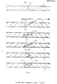
- the arrangement shown in cross section in FIG. 1 using an example of covering layers made of foam strips in a planar extension before laying has a covering layer 1 of width a, which corresponds to the pipe circumference of the pipe to be insulated.
- the width b of the covering layer 2 corresponds to the tube circumference enlarged by the thickness of the covering layer 1.
- the width c of the wrapping layer 3 in turn (and any further layer, not shown here) corresponds to the pipe circumference enlarged by the thicknesses of the preceding layers.
- the wrapping layers 2 and 3 have a step-like offset 9a or 9b here relative to the wrapping layer 1.
- the outer covering layer 3 later has on its upper side along both edge surfaces a closure system 8, for example a slide closure, with the aid of which the two end edges 5a and 5b of the uppermost covering layer 3 forming a butt joint are closed and the laying is terminated.
- the cladding layers 1 to 3 which are connected perpendicular to the plane of the drawing in the direction of the length of the cladding layers over a small width by iie connections 4 in the form of point or line stitching, can be displaced relative to one another over the remaining width.
- the illustrated preferred position of the connections 4 near the end edges 5c and 5d of the wrapping layers 1 and 2 corresponds to the position of the adhesive tape 6 near the offset and the end edge 5d at the start of the arrangement and a start of assembly on the left side in FIG. 1.
- connections 4 can also be arranged at any point in the width of the wrapping layers, that is to say shifted to the right in the drawing, but in accordance with the greater displacement of the wrapping layers relative to one another, a larger offset 9a and 9b must also be provided when wrapping.
- FIG. 2 shows in cross section to the pipe axis of the pipe 10 a multi-layer arrangement of sheathing inserts made of foamed plastics in an originally planar arrangement during the sheathing process according to the method for producing the multi-layer pipe insulation.
- the wrapping layer 1 fastened to the pipe 10 by the fixation 6 in the form of an adhesive tape running in the direction of the longitudinal axis of the pipe is connected by the connection 4 to the wrapping layers 2 and 3 and, due to the individual movability in the area of its remaining width, has changed from the wrapping layers 2 and 3 removed and was already applied to the circumference of the tube and formed into the innermost cladding layer, the butt joint 11 being shown as closed.
- the wrapping layer 2 has already inclined somewhat in the wrapping direction indicated by an arrow and now has a gap with respect to the wrapping layer 3, which consists of somewhat stiffer foam material and has only slightly lowered in the wrapping direction of the arrow.
- the wrapping layers 2 and 3 are then formed into the wrappings indicated by dashed circles; the end edges 5a and 5c close with the associated end edges (not shown) at the other end of the wrapping layers 2 and 3 to form the respective butt joint and the wrapping process is ended by closing the closure 8.
- Figure 3 shows in cross section to the tube axis a tube 10 with an applied multi-layered pipe insulation, obtained by the method according to the invention of a multilayer plan arrangement of cladding layers (corresponding to Fig. 1) by fixing or attaching the K ieoeoanaes 6 on the tube Umhullung of the tube was produced in the direction of wrapping indicated by arrow and closing of the closure system 8.
- the edge surfaces of the respective cladding layers, here cut perpendicular to the foam layer, have closed to form the radial butt joints 11.
- FIG. 4 shows a pipe insulation produced according to the invention on the pipe 10, in which, in contrast to FIG. 1, four sheathing layers have butt joints.
- the lowermost covering layer 1 consists of a thinner and / or softer foam t offlage, which is provided on the side facing the tube with a coating 20 made of aluminum foil reflecting the heat rays.
- the outer wrapping layer 3 is thicker than the layers below formed, can consist of a harder foam material and has a coating 21 on the outside, which is designed for example as weather-resistant, mechanically or chemically stressable or flame-retardant skin or can be provided with a special coloring.
- the front edges of the wrapping layers of the arrangement used are cut at an angle to the spreading of the wrapping layers and result in overlapping butt joints 11.
- the differently cut end edges 5 of the wrapping layers shown in FIG. 5 result in the butt joints 11.
- the oblique cuts of the butt joints 11 are able to compensate for tolerances.
- the cuts of the butt joints 11 are generally produced by flame cutting and improve the adhesion of the end faces to one another.
- the arrow drawn indicates the wrapping direction which, in the cutting directions shown, results in the preferred overlapping of the front edge on the top of the wrapping layers.
- FIGS. 6 and 7 show examples of the sheathing of several pipes with a common multi-layer insulation, which was produced from multi-layered plan arrangements of sheathing layers made of foam strips.
- the tubes are fixed against one another in a manner not shown by assembly that has already taken place or by spacers.
- the sheathing started on the left tube in the drawing and carried out in the direction of the arrow is facilitated in the example by the fixations 6 in the form of adhesive strips applied to the left and right tube in the direction of the longitudinal axis of the tube before the sheathing.
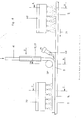
- FIG. 9 schematically shows the design of the device for connecting a plurality of foam strips as wrapping layers and producing thick-walled insulating tubes therefrom.
- two, three or more foam strips 1, 2, 3 can be connected and shaped with an appropriate number of heating devices and supply devices to form an insulating tube.
- only insulating tubes made of two foam strips 1, 2 with two heating devices 70, 90 are shown. From FIG. 14 it can be seen that the foam strips 1, 2 have different lengths depending on their thickness and the insulation tube diameter, preferably the foam strips 1 , 2 brought together in the middle and stapled together in the central area 4 by means of a weld seam.
- the foam strip 2 is first heated to its plasticity on its upper side as it passes through the heating device 90, for example infrared radiator, as shown in FIG. 9. Then the second narrower foam strip 1 is applied, which is applied to the foam strip 2 via a guide device 15, 17 and the deflection and pressure roller 30.
- the hot air device 60 is arranged in the inlet and connection area between the pressure roller 30 and the foam strip 2, as a result of which the two foam strips 1, 2 are welded together to form a small weld seam 4.
- the two foam strips 1, 2 then run further into the next heating device 70, in which the surface of the foam strip 1 is heated up to the plastic state.
- insulating tubes 22 can be produced from foam strips made of thermoplastic foam, for example polyolefin foams, such as cross-linked polyethylene foams.
- the foam strips 1, 2 are in this case r from supply roll 100 and further advantages not shown atsrolle over guide rollers 30 to the continuously circulating transport belt 80.
- An adhesive point 40 can also be provided here for the endless joining of the foam strips when changing rolls.
- the foam strip 2 passes through the heating device 90, for example infrared radiators, the upper side of the foam strip being heated up into the thermoelastic or thermoplastic area.
- the next foam strip 1 is then fed onto the top of the foam strip 2, the deflecting roller 30 simultaneously taking over the function of the pressure roller.
- the hot air device 60 is provided for connecting the foam strips 1 and 2 to one another, as a result of which a narrow weld seam is brought about.
- the foam strips run into the form funnel 12 and are then passed through the shaped tube 14 with cooling, guided and pulled off by means of the rollers 16 with further cooling, and the butt joint at point 19, for example by means of a welding device with a heating sword closed the length of the edges of the insulating tube, and after passing through the pressing and pulling device 13, the insulating tube 22 leaves the system.
- a slitting device for slitting the insulating tube for subsequent assembly and a winding device can also be arranged here.
- area 19 instead of welding the insulating tube, a slide closure can also be welded along the two edges of the insulating tube. the insulation the foam strips are fed to the shaping.
- FIG. 13 shows the cross section AA through the heating device 90, in which a foam strip is to be guided first.
- the alignment of the foam strip 2 is effected by means of the guide strips 121, 131 along the longitudinal edges of the foam strip.
- FIG. 11 shows a schematic cross section according to section BB according to FIG. 9 in the area of the pressure roller 30.
- the merging of the foam strips 1 and 2 and the formation of the weld seam 4 is shown, the foam strips are continuously carried on by the conveyor belt 80.
- the strips 1 , 2 are preferably aligned centrally one above the other parallel to their longitudinal extent. However, it is also possible to arrange the foam strip 1 somewhat off-center, but still within the width of the lower, larger foam strip 2. This can be expedient, for example, if the multilayer insulating tube to be produced is to be equipped with a slide closure, as shown in cross section by way of example in FIG. 18.
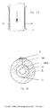
- FIG. 15 shows schematically the shaping of the foam strips 1, 2 connected to one another along the seam 4 in a line shape to form the tube cross section. Since the foam strips 1, 2 can still be easily shifted against each other, a very easy deformation to the tube cross section is possible. Even with insulating tubes with very small inner diameters and large wall thicknesses, it is possible according to the method according to the invention to produce them without internal compression folds. Thinner foam strips are preferably used for the inner layers of the insulating tube and thicker ones for the outer layers, as shown for example in FIG. 17. In the event that the insulating tube is closed in the longitudinal direction with a weld seam 11 during the shaping, If the pipe is subsequently slotted, see slot 23 to enable assembly. This slot can later be closed with an adhesive tape, but it can also be left open because the insulating tube produced by the process is dimensionally stable and true to shape and the slot 23 is not open.
- Insulating pipes of the type described have the advantage of greater flexibility when opening than single-layer insulating pipes and are easy to handle.
Landscapes
- Engineering & Computer Science (AREA)
- Mechanical Engineering (AREA)
- General Engineering & Computer Science (AREA)
- Thermal Insulation (AREA)
Abstract
Description
- Der Gegenstand der Erfindung bezieht sich auf ein Verfahren zum Herstellen mehrschichtiger Isolierrohre aus mehreren Umhüllungslagen aus Schaumstoffstreifen, wobei insbesondere die später die Isolierrohrinnenseite bildende Seite kurzzeitig bis in den thermoelastischen bzw. thermoplastischen Zustand erwärmt und danach der Schaumstoffstreifen quer zu seiner Längserstreckung zum Rohrquerschnitt verformt und längs der Seitenkanten verbundene wird und hiernach hergestellte mehrschichtige Isolierrohre.
- Des weiteren befaßt sich die Erfindung mit einer Vorrichtung zum Durchführen des Verfahrens mit einem umlaufenden Band zum Transport der kontinuierlich zulaufenden Schaumstoffstreifen, einer Heizeinrichtung, einem Formtrichter mit einer gekühlten Formröhre und einer Einrichtung zum Verschließen der Stoßnaht der Seitenkanten.
- Rohrisolationen aus Schaumkunststoffen können, soweit diese von Schaumstoffbahnen oder Streifen ausgehen, beispielsweise durch Verformung von Streifen zur Rohrform und anschließendes Verschließen der in Längsrichtung verlaufenden Stoßfuge durch Schweißen, Kleben o.ä. hergestellt werden (DE-AS 25 03 382 und DE-AS 25 32 406). Solche Herstellverfahren erfordern aufwendige Maschinen und Formen- Die notwendige Dicke der Isolierung erfordert wegen der Rückstellneigung der Schaumstoffe eine Wärmebehandlung mit der Gefahr der Schädigung der Schaumstoffe. Die erhebliche Dicke der Isolierschicht vor allem von Rohren größerer Weite ist nur mit aufwendigen Maßnahmen erreichbar. Mehrschichtige Rohrisolierungen können beispielsweise gemäß DE-OS 19 15 768 durch Umwickeln oder kreuzweises Wickeln in mehreren Schichten hergestellt werden.
- Im Zuge von Energiesparmaßnahmen werden immer dickere und bessere Isolationen für wärmeführende Leitungen, in3besondere Warmwasserleitungen, Heizleitungen etc. gefordert. Im üblichen Installationsbereich sind hierbei die zu isolierenden Rohrdurchmesser überwiegend kleiner als 45 mm, die geforderte Isolationsdicke entspricht etwa einem Rohrdurchmesser. Dies bedeutet beispielsweise bei einem Rohrdurchmesser von 30 mm, daß ein Isolationsrohr aus Schaumstoff mit einer Dicke von 30 mm einen Innendurchmesser von etwa 30 mm und einen Außendurchmesser von 90 mm aufweist. Es ist sehr schwierig, aus dicken Schaumstoffstreifen ein Isolierrohr mit so kleinen Innendurchmessern zu formen, ohne daß Stauchungen und Faltenbildung des Schaumstoffes vermieden werden.
- Eine Aufgabe der Erfindung ist darin zu sehen, eine mehrschichtige Rohrisolation zu schaffen, die möglichst einfach, ggf. auch ohne Erwärmen, direkt auf Rohre aufgebracht werden kann, ggf. vor Ort.
- Eine weitere Aufgabe der Erfindung besteht darin, in einem kontinuierlichen Verfahren mittels Erwärmung dickwandige Isolierrohre herzustellen unter Vermeidung von Faltenbildungen und insbesondere für kleinere Rohrdurchmesser, wie sie in der Installationsisolierung üblich sind. Die Erfindung geht hierbei von mehrschichtigen dickwandigen Isolierrohren aus, die aus mehreren übereinander angeordneten Schaumstoffstreifen aufgebaut sind.
- Gemäß der Erfindung wird ein Verfahren zur Herstellung von mehrschichtigen Isolierrohren aus mehreren Umhüllungslagen aus Schaumkunststoffen vorgeschlagen, bei dem eine mehrschichtige Anordnung von Umhüllungslagen in planer Erstreckung und. vorgegebener Länge und unterschiedlicher Breite, die dem Rohrumfang bzw. dem um die jeweils vorangehend aufgebrachte Dicke der Umhüllungslage vergrößerten Rohrumfang entspricht, vorgesehen wird, deren einzelne Umhüllungslagen in Rohrumfangsrichtung versetzt zur benachbarten Umhüllungslage angeordnet werden und wobei jede Umhüllungslage in Richtung der Rohrlängsachse mit der benachbarten Umhüllungslage teilweise, wie linienförmig, verbunden wird, danach die mehrschichtige Anordnung zum Isolierrohr geformt wird, wobei die Stirnkanten jeder Umhüllungslage sich zu einer geschlossenen Hülle schließen und zumindest die dabei gebildete Stoßfuge der äußersten Umhüllungslage außen und/oder in der Stoßfuge verschlossen wird.
- Durch die nur linienförmige bzw. in geringer Breite erfolgende Verbindung der Umhüllungslagen bleiben die Umhüllungslagen senkrecht zu der Verbindung in Umfangsrichtung des Rohres verschiebungsfähig und dadurch leicht dem Rohrumfang anpaßbar und werden so leicht aus der planen Erstreckung zur Rohrisolation formbar.
- Die Herstellung der Rohrisolation, ausgehend von der planen, bevorzugt .vorgefertigten Anordnung aus mehreren Schaumstofflagen, erfolgt durch Biegen zur Rohrform auf dem Rohr selbst, bis sich die Stirnkanten jeder Umhüllungslage berühren und anschließendes Verschließen der in Richtung der Rohrlängsachse verlaufenden Stoßfuge zumindest der äußersten Umhüllungslage. Die Herstellung der Rohrisolation kann am Ort der Verlegung der Rohre vorgenommen werden. Selbst lange Rohre bzw. Rohrabschnitte und Rohre großen Durchmessers bzw. Rohrbündel können am Ort mittels einfacher Hilfsmittel, z.B. Rinnen oder Kästen, aber auch ohne Hilfsmittel, mit der Rohrisolation umhüllt werden. Wesentlich erleichtert wird die Aufbringung der Anordnung mehrerer Schaumstofflagen und die Verformung zur Umhüllung durch Fixierung der innersten Umhüllungslage am Rohr, was durch Kleben mit z.B. einem Kleber oder durch einen schmalen Klebestreifen unter der innersten Umhüllungslage, bevorzugt nahe an deren Anfang, über die Länge des Rohres geschehen kann. Zweckmäßig ist ein Klebeband bzw. beidseitiges Klebeband bereits auf der untersten Seite der untersten Umhüllungslage befestigt, dessen Schutzschicht abgezogen werden kann.
- Der Umhüllungsvorgang beginnt durch Fixierung der Unterseite der innersten Umhüllungslage am Rohr parallel zur Rohrlängsachse, soweit im bevorzugten Falle eine Fixierung vorgesehen ist. Dann soll bei abgestuft, abgeschrägt oder versetzt ausgebildeter Stoßfuge die Profilierung der in Umhüllungsrichtung zuletzt aufgebrachten Stirnkante der Stoßfuge oben übergreifen. Ebenso soll ein ggf. berei auf der äußersten Umhüllungslage nagebrachter Verschluß über der in Umhüllungsrichtung zuletzt aufgebrachten Stir kante liegen.. Die Breite jeder Umhüllungslage soll so beschaffen sein, daß die kürzeste Umhüllungslage als innerste und jede folgende darüber sich dem jeweiligen Umfang anpassen und die Stoßfugen sich bei der Umhüllung schlies sen. Da aber durch vorgegebene geringere oder größere Steifigkeit die Umhüllungslagen sich auf der Unterseite stauchen und oberhalb einer etwa in der Mitte der Lagendicke liegenden Biegelinie dehnen, hat im allgemeinen die mittlere Dicke jeder Bahn (unter Berücksichtigung der Schnittlinie der Stoßfuge) der Länge der Abwicklung diese gedachten Biegelinie zu entsprechen.
- Für die leichte Verformung der planen Anordnung der Umhül lungslagen zur Rohrumhüllung ist wesentlich, daß jede Lage von vergleichsweise geringer Dicke ist, die abhängig von der Steifigkeit des jeweils verwendeten Schaumkunststoffe sowie des Rohrdurchmessers höchstens einen oder wenige cm vorzugsweise 5 bis 20 mm, beträgt. Wesentlich ist weiter die z.B. linienförmig parallel zur Rohrlängsachse verlaufende Verbindung der Umhüllungslagen mit der jeweils benachbarten Lage und die im übrigen freie Verschiebbarkeit der Umhüllungslagen gegeneinander auf ihrer übrigen Berührungsfläche für die leichte Ausführung des fortschreitenden Umhüllungsvorgangs.
- Die einzelnen Umhüllungslagen können aus gleichen oder verschiedenen Schaumkunststoffen, gleicher oder verschiedener Dicke bestehen. Bevorzugtes Material ist vernetzter oder ggf. unvernetzter Polyethylenschaumstoff. Zweckmäßig wird die. innerste Umhüllungslage dünner als die folgenden sein und ggf. aus biegsameren Schaumstoffen gebildet sein als die folgenden, die bei dem Umhüllungsvorgang weniger eng gebogen werden. Wenn gewollt, kann die innerste wie auch die äußerste Schicht aus einem anderen flächigen Material bestehen. Solche flächigen Materialien sind u.a. Metallfolien wie z.B. Aluminiumfolien oder Kunststofffolien. Diese Schichten können auch mit der innersten ode äußersten Umhüllungslage durch z.B. Laminieren oder Klebe verbunden sein. Sie dienen den verschiedensten Aufgaben, z.B. als Dampfsperre oder mechanischer Schutz, zur Farbgebung,. als Schutz vor Entflammung oder gegen Witterungsein flüsse. Weiter hat sich die Ansinterung der Oberfläche de äußersten Lage gegen mechanische Beanspruchungen bewährt.
- Besonders einfach und daher sehr bevorzugt ist die Herstellung der mehrschichtigen Rohrisolation bei Verwendung einer vorgefertigten mehrschichtigen Anordnung von Umhüllungslagen aus Schaumkunststoffen in planer Erstreckung, deren einzelne Umhüllungslagen bereits das Format zum Umhüllen von Rohren bestimmter Umfänge und ggf. bestimmter Längen besitzen und zweckmäßig bereits die genannte linienförmige Verbindung zur benachbarten Lage aufweisen Mehrere solcher Anordnungen von Umhüllungslagen in planer Erstreckung können, unabhängig oder nacheinander, auf ein Rohr aufgebracht werden.
- Weiterer Gegenstand der Erfindung ist daher eine mehrschichtige Anordnung von Umhüllungslagen aus Schaumkunststoffen in planer Erstreckung für die Rohrisolierung von Rohren aus Metallen, Kunststoffen, Keramik o.dgl. von unterschiedlicher Breite der jeweiligen Umhüllungslagen, die dem Rohrumfang bzw. dem um die vorangehend aufzubringende Dicke der Umhüllungslage vergrößerten Rohrumfang entspricht, deren einzelne Umhüllungslagen in Rohrumfangsrichtung versetzt zur benachbarten Umhüllungslage angeordnet sind und worin die Umhüllungslagen in Richtung der Rohrlängsachse mit der benachbarten Umhüllungslage miniestens linienförmig verbunden sind.
- Besonders vorteilhaft und wesentlich ist die genannte Ver bindung der Umhüllungslagen in der Anordnung durch die nur schmale Verbindung in Richtung der späteren Rohrlängsachse, da zueinander gehörige Umhüllungslagen mit der für den jeweiligen Rohrumfang passenden Breite und geeigneter Versetzung dadurch montagefertig vorliegen.
- Die vorgefertigte plane Anordnung von Schaumstofflagen kann als ebene Lage mehrerer Schaumstoffbahnen- bzw. streifen einfach verpackt und versandt werden. Ausgangsstoff für die Anordnung sind serienmäßige Kunststoffschaumbahnen.
- Zur Herstellung der Anordnung für ein Rohr bestimmten Umfangs werden aus Schaumstoffbahnen Umhüllungslagen der beabsichtigten Länge geschnitten, wobei die Breite der bei der Ummantelung innersten Lage dem Rohrumfang entspricht, und jede folgende Lage eine größere Breite hat, die sich aus dem Umfang der Umhüllung durch die vorangehende Lage ergibt. Diese Umhüllungslagen werden versetzt gegeneinander, bevorzugt treppenförmig versetzt aufeinandergelegt, so daß jede folgende Umhüllungslage breiter als die vorangehende ist. Die Versetzung braucht nur gering zu sein, zweckmäßig aber mehr als eine Lagendicke, d.h. einen oder wenige cm, kann jedoch auch mehr betragen. Entlang ihrer )Länge wird jede Umhüllungslage mit der benachbarten auf einer geringen Breite durch Kleben, Schweißen, Nähen o.dgl. verbunden. Diese Verbindungen können sowohl über die gesamte Länge durchgehend oder mit Unterbrechungen als Punkt- oder Streckenheftung ausgeführt sein. Die Ver- 5bindungen sind in einer bevorzugten Ausführungsform nahe der Versetzung angeordnet. Das erleichtert die Umhüllung, soweit bevorzugt der Umhüllungsvorgang an der Versetzung beginnt, da die Umhüllungslagen bei Fortschreiten der Umhüllung in Drehrichtung gegeneinander verschiebbar blei ben.
- Um die Umhüllung des Rohres zu erleichter, ist bevorzugt an der planen Anordnung unter der innersten Umhüllungslage eine am Rohr anzubringende Fixierung vorgesehen. Eine Fixierung am Beginn der untersten Lage nahe der Versetzung ist zweckmäßige soweit dort der Umhüllungsvorgang beginnt. Die Fixierung erfolgt bevorzugt mit einem parallel zur Rohrachse verlaufenden Klebeband mit abziehbarer Schutzschicht, das bevorzugt bereits auf der vorgefertigten Anordnung angebracht ist. Die Fixierung kann auch durch mit Wärme oder Lösemitteln aktivierbare Kleber erfolgen. Die oberste, später außenliegende Umhüllungslage der planen Anordnung trägt bevorzugt bereits im vorgefertigten Zustand ein Verschlußsystem für die oberste Stoßfuge in Richtung der Rohrlängsachse, beispielsweise einen Gleitverschluß, Ziehverschluß, Klettenverschluß o.ä. Jedoch kann der Verschluß auch durch Schweißen, Kleben o.dgl. oder durch Anbringung eines der genannten Verschlüs se nach Verformen der Anordnung zur Ummantelung erfolgen. Die durch die beiden Stirnkanten jeder Umhüllungslage bebildete Berührungsfläche der späteren Stoßfuge kann ver--schiedene Gestalt haben. Im einfachsten Falle ist die Umhüllungslage senkrecht geschnitten, wodurch beide Stirnkanten nach Umhüllung eine radiale Stoßfuge bilden. Bei schräg zur Ausbreitung der Umhüllungslage erfolgendem Schnitt ergeben sich Stirnkanten der Umhüllungslage, die sich überlappend berühren. Nicht ebene Schnitte ergeben besonders große, die Umhüllung erleichternde Berührungsflächen. Sofern im bevorzugten Fall die am Rohr anzubringende Fixierung wie auch die Verbindung der Umhüllungslage nahe bzw. im Bereich der Versetzung angeordnet sind und folglich dort der Umhüllungsvorgan beginnt, ist bevorzugt die zuletzt gelegte Stirnkante im Falle einer abgestuften, abgeschrägten oder profilierten Ausbildung der Stirnkanten so ausgebildet, daß die Oberseite der Stirnkante in Umhüllungsrichtung übergreift.
- Bei den mehrschichtigen Anordnungen von Umhüllungslagen aus Schaumkunststoffen in planer Erstreckung und damit ebenso bei mehrschichtigen Rohrisolierungen können die Versetzungen verschieden groß bemessen sein, die linienförmig parallel zur Rohrachse verlaufenden Verbindungen der Umhüllungslagen an verschiedenen Stellen der Breite der Umhüllungslagen angeordnet sein, sowie die Fixierung an verschiedenen Stellen der Breite der untersten Umhüllungslage liegen.
- Im bereits beschriebenen bevorzugten Fall ist die Verset- zung jeder Umhüllungslage gegenüber der nächsten gering d.h. beträgt einige Centimeter. Dann liegen bevorzugt auch die Verbindungen nahe an der Versetzung bzw. nahe den Stirnkanten der jeweils oberen Umhüllungslage. Eine vorhandene Fixierung liegt unter der innersten Umhüllungslage nahe bei deren Stirnkante. Dieser in Figur 1 dargestellte Fall führt zu planen Anordnungen der kleinsten Gesamtvreite und höchster Verschiebbarkeit der einzelnen Umhüllungslagen in Richtung des Rohrumfangs. Als weiterer Fall ist der zu nennen mit einer maximalen Breite der Versetzung und einer Verbindung mit der benachbarten Umhüllungslage auf der kleinen verbleibenden Berührungsfläche zu dieser und einer Fixierung im Bereich der Stirnkante der untersten Umhüllungslage. Es können auch, bei an sich beliebiger Breite der Versetzung, die Verbindungen auf der Breite der Umhüllungslagen zum anderen Ende mehr oder weniger weit verschoben sein, jedoch liegen zweckmäßig dann die Verbindungen und die Fixierung im wesentlichen tangential untereinander und der Abstand der Verbindung zu den Stirnkanten der zugehörigen Umhüllungslagen ist stets so zu wählen, daß nach der Umhüllung die Stoßfugen zueinander tangential versetzt sind.
- Der Umhüllungsvorgang beginnt stets an der Fixierung. Gemäß der Erfindung können auch mehrere Rohre oder Bündel von Rohren gemeinsam mit der erfindungsgemäßen Anordnung von Umhüllungslagen umhüllt werden. Voraussetzung hierzu ist lediglich, daß der effektive Umfang des Rohrbündels bekannt ist, um die Breite jeder Umhüllungslage der mehrschichtigen Anordnung vorfertigen zu können, sofern nicht in diesem Falle aus einer vorgefertigten planen Anordnung mit am Anfang verbundenen Lagen am Ort erst die erforderlichen Breiten jeder Lage geschnitten werden.
- Bevorzugt ist nur die oberste Stoßfuge verschlossen. Die oberste Stoßfuge ist bevorzugt auf ihrer ganzen Länge verschlossen, doch kann der Verschluß auch Unterbrechungen aufweisen. Der Verschluß ist in der Fuge durch z.B. Einbringen eines Klebers oder durch Verschweißung möglich, jedoch ist ein flächiger Verschluß außen z.B. durch ein Klebeband oder ggf. durch eine den Umfang ganz oder teilweise umfassende z.B. aufgeklebte Folie bevorzugt. Ggf. können auch darunterliegende Stoßfugen, insbesondere durch ein Klebeband, verschlossen sein. Die aus den beiden Stirnkanten der jeweiligen Umhüllungslage gebildete Stoßfuge kann radial liegen oder abgestuft, abgeschrägt oder profiliert ausgebildet sein. Bevorzugt ist die auf dem Rohr anliegende unterste Umhüllungslage bzw. eine ggf. unter dieser liegende Folie aus Kunststoff, Metall oder dgl., welche ganz oder teilweise mit der untersten Umhüllungslage verbunden ist, am Rohr in Richtung der Längsache linienförmig, zumindest teilweise, d.h. ggf. mit Unterbrechungen fixiert, z.B. durch Kleben mit einem Kleber oder bevorzugt mittels eines Klebebandes. Sehr bevorzugt sind die Umhüllungslagen in Richtung der Rohrlängsachse mindestens linienförmig auf geringer Breite, ggf. mit Unterbrechungen verbunden. Bevorzugt liegen diese Verbindungen nahe den Stirnkanten, in welchem Falle auch die Fixierung der untersten Umhüllungslage nahe den Randflächen liegt. Im allgemeinen haben die Rohrisolationen eine standardisierte Länge von z.B. 1 oder 2 m; die auf einem verlegten Rohr bzw. Rohrbündel oder noch zu verlegendem Rohr gemeinsam die Isolierung der gesamten Länge ergeben. Es sind auch Rohrisolierungen angepaßt an Rohrabschnitte-bestimmter Länge möglich.
- Die erfindungsgemäße Rohrisolation ergibt unverminderte Isolierwerte bzw. Wärmedämmwerte, bezogen auf die Dämmwerte des Schaumkunststoffes der jeweiligen Lagen, da beliebig dicke Umhüllungen auch für Rohre großen Durchmessers gefertigt werden können und die Meßwerte der Wärmedämmung über den gesamten Umfang der Umhüllung gleicl sind, weil die Stirnkanten der jeweiligen Lagen gegeneinander tangential, d.h. in Umhüllungsrichtung versetzt sind und keine Schädigung der Schaumkunststoffe durch Erwärmen, Schweißen oder Kleben erfolgt.
- In Weiterbildung der Erfindung wird ein Verfahren vorgeschlagen, bei dem eine entsprechende Anzahl von Schaumstoffstreifen in der Reihenfolge der Umhüllungslagen von außen nach innen parallel zu ihrer Längserstreckung, vorzugsweise mittig, innerhalb der Breite des jeweils vorhergehenden Schaumstoffstreifens nacheinander zusammengeführt werden, wobei jeweils ein noch nicht erwärmter Schaumstoffstreifen auf einen erwärmten Schaumstoffstreifen gelegt wird und die beiden Schaumstoffstreifen unter Bildung einer schmalen Naht verschweißt werden.
- Durch den Einsatz mehrerer Schaumstoffstreifen zum Herstellen des dickwandigen Isolierrohres wird erreicht, daß das kontinuierliche Herstellungsverfahren schnell durchgeführt werden kann, da dünne Schaumstoffstreifen wesentlich schneller erwärmt werden können als dicke und damit das Verfahren zum Herstellen des Isolierrohres mit kurzen Erwärmungszeiten durchgeführt werden kann. Es ist möglich, nach dem erfindungsgemäßen Verfahren für die Isolierrohre Schaumstoffstreifen unterschiedlicher Dicken gemeinsam zu verarbeiten, wobei insbesondere dünnere Schichten für den inneren Teil des Isolierrohres mit den kleinen Durchmessern gewählt werden können und dickere Schaumstoffschichten für den Außenteil des Isolierrohres- Darüber hinaus können auch Schaumstoffstreifen unterschiedlicher Qualitäten eingesetzt werden, wobei wärmebeständigere Qualitäten die Isolierrohrinnenschicht bilden können und beispielsweise witterungsstabile oder flammfestere Schaumstoffqualitäten die Isolierrohraußenseite. Das erfindungsgemäße Verfahren hat auch den Vorteil, daß sich die Wärme des bereits erwärmten Schaumstoffstreifens auf den nachfolgend zulaufenden, noch nicht erwärmten Schaumstoffstreifen überträgt, so daß dieser nicht nur auf der Oberseite erwärmt wird, sondern auch auf der Unterseite, wodurch infolge der gleichmäßigen Erwärmung des Schaumstoffstreifens eine Art Temperung; d.h. spannungsfrei machen eintritt und das später geformte Isolierrohr sehr formstabil und spannungsarm ist.
- Nach dem erfindungsgemäßen Verfahren werden die mehreren aus den Schaumstoffstreifen gebildeten Schichten zuerst nur längs einer schmalen Naht durch Schweißen miteinander verbunden, so daß die Schaumstoffstreifen beim Formen zum Isolierrohr noch leicht gegeneinander verschoben werden können, wodurch eine leichte Formgebung und gute Anpas- sung ermöglicht ist. Durch das Verbinden der Seitenkanten des Isolierrohres zum geschlossenen Isolierrohr entsteht dann an einer gegenüberliegenden Stelle eine weitere Verbindungsnaht. Das Isolierrohr wird dann zum Zwecke der Montage wieder aufgeschlitzt an einer Stelle außerhalb der beiden genannten Verbindungsnähte. Auch hier verbleibt dann eine gewisse Beweglichkeit der einzelnen Isolierschichten gegeneinander, da sie in diesen Bereichen nicht untereinander verbunden sind, wodurch die Montage erleichtert wird.
- In Weiterbildung des erfindungsgemäßen Verfahrens ist vorgesehen, daß die Schaumstoffstreifen während der Erwärmung längs der Seitenkanten an gekühlten Führungsleisten vorbeigeführt werden. Damit ist eine genaue Ausrichtung der Schaumstoffstreifen möglich, und zugleich werden die Seitenränder auch vor Überhitzung geschützt; dies gilt insbesondere für die überstehenden Ränder der nicht die oberste Lage bildenden Schaumstoffstreifen, die während der Erwärmung des obersten Schaumstoffstreifens ebenfalls mittels gekühlter Führungsleisten abgedeckt werden.
- Eine vorteilhafte Ausbildung der Vorrichtung zur Durchführung des erfindungsgemäßen Verfahrens enthält mehrere Heizeinrichtungen, die hintereinander angeordnet sind und die mit kühlbaren und verstellbaren Führungsleisten für die Seitenränder bzw. Seitenkanten der durchlaufenden Schaumstoffstreifen ausgebildet sind und die für die Zuführung der Schaumstoffstreifen auf den jeweils vorerwärmten Schaumstoffstreifen eine Umlenk- und Andrückrolle sowie ein Schweißgerät, beispielsweise Heißluftschweißgerät, aufweisen.
- Damit ist es möglich, eine bekannte Vorrichtung zum Durchführen des Verfahrens, wie sie beispielsweise in der deutschen Patentschrift 25 32 406 beschrieben ist, und auch ähnliche Einrichtungen wirtschaftlich zu ergänzen, um auch dickwandige Isolierrohre aus mehreren Schaumstoffstreifen kontinuierlich herzustellen.
- In der Zeichnung ist die Erfindung in Ausführungsbeispielen beschrieben. Es zeigen
- Figur 1 eine Anordnung von Umhüllungslagen in planer Erstreckung,
- Figur 2 den Umhüllungsvorgang um ein Rohr mit einer solchen planen Anordnung,
- Figur 3 und
4 mit der Isolierung umhüllte Rohre, - Figur 5 unterschiedlich geschnittene Endflächen von Umhüllungslagen,
- Figur 6 und
7 Umhüllungen aus mehrschichtigen Isolationen für Rohrbündel, - Figur 8 eine schematische Gesamteinsicht einer Vorrichtung zum Herstellen von Isolierrohren aus Schaumstoffstreifen,
- Figur 9 einen vergrößerten Ausschnitt in schematischer Darstellung für den Zusammenführungsbereich der Schaumstoffstreifen gemäß Figur 8,
- Figur 10 den Schnitt AA nach Figur 9,
- Figur 11 den Schnitt BB nach Figur 9,
- Figur 12 den Schnitt CC nach Figur 9,
- Figur 13 die Ansicht D nach Figur 9,
- Figur 14- die Zuordnung der Schaumstoffstreifen gemäß Figur 9,
- Figur 15 die Bildung des Isolierrohres im Querschnitt gemäß Figur 9,
- Figur 16 und 17 zwei Isolierrohrquerschnitte gemäß Figur 9,
- Figur 18 einen Isolierrohrquerschnitt mit Gleitverschluß gemäß Figur 9.
- Die in Figur 1 im Querschnitt an einem Beispiel gezeigte Anordnung von Umhüllungslagen aus Schaumstoffstreifen in planer Erstreckung vor der Verlegung weist eine Umhüllungslage 1 der Breite a auf, die dem Rohrumfang des zu isolierenden Rohres entspricht. Die Breite b der Umhüllungslage 2 entspricht dem um die Dicke der Umhüllungslage 1 vergrößerten Rohrumfang. Die Breite c der Umhüllungslage 3 wiederum (und jede weitere, hier nicht gezeigte Lage) entspricht dem durch die Dicken der vorangehenden Lagen vergrößerten Rohrumfang. Die Umhüllungslagen 2 und 3 weisen einen hier treppenförmigen Versatz 9a bzw. 9b gegenüber der Umhüllungslage 1 auf. Am Beginn der innersten Umhüllungslage 1 ist auf deren Unterseite ein sich entlang der Länge der Umhüllungslage erstreckendes Klebeband 6 mit abziehbarer Schutzschicht 7 befestigt, mit dem die Anordnung auf dem Rohr entlang seiner Achse fixiert und gehalten wird. Die nach Verlegung der mehrschichtigen Rohrisolation später außenliegende Umhüllungslage 3 weist auf ihrer Oberseite entlang beider Randflächen ein Verschlußsystem 8, z.B. einen Gleitverschluß auf,mit dessen Hilfe die beiden eine Stoßfuge bildenden Stirnkanten 5a und 5b der obersten Umhüllungslage 3 verschlossen und die Verlegung beendet wird. Die senkrecht zur Zeichenebene in Richtung ier Länge der Umhüllungslagen auf geringer Breite durch iie Verbindungen 4 in Form von Punkt- oder Streckenheftungen verbundenen Umhüllungslagen 1 bis 3 sind auf der ibrigen Breite gegeneinander verschiebbar. Die dargestellte bevorzugte Lage der Verbindungen 4 nahe den Stirnkanter 5c und 5d der Umhüllungslagen 1 und 2 entspricht der Lage des Klebebandes 6 nahe der Versetzung und der Stirnkante 5d am Beginn der Anordnung und einem Beginn der Montage auf der in Figur 1 linken Seite. Wenn gewollt, können die Verbindungen 4 auch an beliebiger Stelle der Breite der Umhüllungslagen angeordnet, d.h. in der Zeichnung nach rechts verschoben sein, jedoch ist dann entsprechend der größeren Verschiebung der Umhüllungslagen gegeneinander bei Umhüllung auch ein jeweils größerer Versatz 9a und 9b vorzusehen.
- Figur 2 zeigt im Querschnitt zur Rohrachse des Rohres 10 eine mehrschichtige Anordnung von Umhüllungseinlagen aus Schaunkunststoffen in ursprünglich planer Anordnung währen des verfahrensgemäßen Umhüllungsvorganges zur Herstellung der mehrschichtigen Rohrisolation. Die durch die Fixierung 6 in Form eines in Richtung der Rohrlängsachse verlaufenden Klebebandes am Rohr 10 befestigte Umhüllungslage 1 ist durch die Verbindung 4 mit den Umhüllungslagen 2 und 3 verbunden und hat sich durch die einzelne Bewegbarkeit im Bereich ihrer übrigen Breite von den Umhüllungslagen 2 und 3 entfernt und wurde bereits an den Rohrumfang angelegt und zur innersten Umhüllungslage geformt, wobei die Stoßfuge 11 als geschlossen dargestellt ist. Die Umhüllungslage 2 hat sich bereits etwas in die durch einen Pfeil angegebene Umhüllungsrichtung geneigt und weist nun einen Spalt gegenüber der Umhüllungslage 3 auf, die aus etwas steiferem Schaumstoffmaterial besteht und sich nur wenig in Umhüllungsrichtung des Pfeils gesenkt hat. Durch einzelnes oder gemeinsames Schieben in Pfeilrichtung werden darauf auch die Umhüllungslagen 2 und 3 zu den durch gestrichelte Kreise angedeuteten Umhüllungen geformt; wobei sich die Stirnkanten 5a und 5c mit den zugehörigen (nicht dargestellten) Stirnkanten am anderen Ende der Umhüllungslagen 2 und 3 zur jeweiligen Stoßfuge schließen und der Umhüllungsvorgang durch Schließen des Verschlusses 8 beendet wird.
- Figur 3 zeigt im Querschnitt zur Rohrachse ein Rohr 10 mit aufgebrachter mehrschichtiger Rohrisolation, die nach dem Verfahren gemäß der Erfindung aus einer mehrschichtigen planen Anordnung von Umhüllungslagen (entsprechend Fig. 1) durch Fixierung bzw. Befestigen des Kieoeoanaes 6 am Rohr, Umhullung des Rohres in der durch Pfeil angedeuteten Umhüllungsrichtung und Schließen des Verschlußsystems 8 hergestellt wurde. Die Randflächen der jeweiligen, hier senkrecht zur Schaumstofflage geschnittenen, Umhüllungslagen haben sich zu den radialen Stoßfugen 11 geschlossen.
- Figur 4 zeigt eine erfindungsgemäß hergestellte Rohrisolation auf dem Rohr 10, in der abweichend von Figur 1 vier Umhüllungslagen abgeschrägt ausgebildete Stoßfugen aufweisen. Die unterste Umhüllungslage 1 besteht aus einer dünneren und/oder weicheren Schaumstofflage, die auf der dem Rohr zugewandten Seite mit einer die Wärmestrahlen reflektierenden Beschichtung 20 aus Aluminiumfolie versehen ist. Die äußere Umhüllungslage 3 ist gegenüber den darunterliegenden Lagen dicker ausgebildet, kann aus einem härteren Schaumstoffmaterial bestehen und trägt auf der Außenseite eine Beschichtung 21, welche beispielsweise als witterungsbeständige, mechanisch bzw. chemisch beanspruchbare oder flammwidrige Haut ausgebildet ist oder mit einer besonderen Farbgebung versehen werden kann. Die Stirnkanten der Umhüllungslagen der verwendeten Anordnung sind schräg zur Ausbreitung der Umhüllungslagen geschnitten und ergeben sich überlappend berührende Stoßfugen 11.
- Die in Figur 5 dargestellten, unterschiedlich geschnittenen Stirnkanten 5 von Umhüllungslagen ergeben die Stoßfugen 11. Die schrägen Schnitte der Stoßfugen 11 vermögen Toleranzen auszugleichen. Die Schnitte der Stoßfugen 11 werden im all- ,gemeinen durch Brennschneiden erzeugt und verbessern die Haftung der Endflächen aneinander. Der eingezeichnete Pfeil gibt die Umhüllungsrichtung an, die bei den dargestellten Schnittrichtungen das bevorzugte Übergreifen der Stirnkante auf der Oberseite der Umhüllungslagen ergibt.
- Die Figuren 6 und 7 schließlich zeigen Beispiele für die Ummantelung mehrerer Rohre mit einer gemeinsamen mehrschichtigen Isolation, die aus mehrschichtigen planen Anordnungen von Umhüllungslagen aus Schaumstoffstreifen hergestellt wurde. Die Rohre sind in nicht gezeigter Weise durch bereits erfolgte Montage oder durch Abstandshalter gegeneinander festgelegt. Die am in der Zeichnung linken Rohr begonnene und in Richtung des gezeichneten Pfeils erfolgte Umhüllung wird im Beispiel durch die Fixierungen 6 in Form von vor der Umhüllung auf dem linken und rechten Rohr aufgebrachten Klebestreifen in Richtung der Rohrlängsachse erleichtert.
- In der Fig. 9 ist die Ausbildung der Vorrichtung zum Verbinden mehrerer Schaumstoffstreifen als Umhüllungslagen und Herstellen von dickwandigen Isolierrohren hieraus schematisch dargestellt. Entsprechend der Dicke des gewünschten Isolierrohres können zwei, drei oder mehr - Schaumstoffstreifen 1, 2, 3 mit einer entsprechenden Anzahl von Heizeinrichtungen und Zuführungseinrichtungen zu einem Isolierrohr verbunden und geformt werden. In dem gezeigten Beispiel sind lediglich Isolierrohre aus zwei Schaumstoffstreifen 1, 2 mit zwei Heizeinrichtungen 70, 90 dargestellt- Aus der Fig. 14 ist ersichtlich, daß die Schaumstoffstreifen 1, 2 entsprechend ihrer Dicke und dem Isolierrohrdurchmesser unterschiedliche Längen aufweisen, vorzugsweise werden die Schaumstoffstreifen 1, 2 mittig aufeinandergeführt und im mittleren Bereich 4 mittels einer Schweißnaht zusammengeheftet. In Fertigungsrichtung, die der Pfeil 24 andeutet, wird nach Fig. 9 zuerst-der Schaumstoffstreifen 2 beim Durchlaufen der Heizeinrichtung 90, beispielsweise Infrarotstrahler, auf seiner Oberseite bis zur Plastizität erwärmt. Hierauf wird.dann der zweite schmalere Schaumstoffstreifen 1 aufgebracht, der über eine Führungseinrichtung 15, 17 und die Umlenk- und Andrückrolle 30 auf den Schaumstoffstreifen 2 aufgebracht wird. Im Zulauf- und Verbindungsbereich zwischen Andrückrolle 30 und Schaumstoffstreifen 2 ist das Heißluftgerät 60 angeordnet, wodurch die beiden Schaumstoffstreifen 1, 2 in geringer Breite unter Bildung der Schweißnaht 4 miteinander verschweißt werden. Dann laufen die beiden Schaumstoffstreifen 1, 2 weiter in die nächste Heizeinrichtung 70, in der die Oberfläche des Schaumstoffstreifens 1 bis in den plastischen Zustand hin erwärmt wird. Je nach der gewünschten Dicke des Isolierrohres kann nun noch eine weitere Zuführung eines weiteren Schaumstoffstreifens und eine weitere Heizeinrichtung nachgeschaltet werden, bis dann nach Erreichen der gewünschten Dicke Mit der in Fig. 8 dargestellten Vorrichtung können aus Schaumstoffstreifen aus thermoplastischem Schaumstoff, beispielsweise Polyolefinschaumstoffen, wie vernetzten Polyäthylenschaumstoffen, Isolierrohre 22 hergestellt werden. Die Schaumstoffstreifen 1, 2 werden hierbei von Vorratsrolle 100 und einer weiteren nicht gezeigten Vor- ratsrolle über Umlenkrollen 30 auf das endlos umlaufende Transportband 80 auf. Hier kann auch noch eine Klebestelle 40 vorgesehen sein zum endlosen Aneinanderfügen der Schaumstoffstreifen bei Rollenwechsel. Zuerst durchläuft der Schaumstoffstreifen 2 die Heizeinrichtung 90, beispielsweise Infrarotstrahler, wobei die Oberseite des Schaumstoffstreifens bis in den thermoelastischen bzw. thermoplastischen Bereich erwärmt wird. Auf die Oberseite des Schaumstoffstreifens 2 wird dann der nächste Schaumstoffstreifen 1 zugeführt, wobei die Umlenkrolle 30 gleichzeitig die Aufgabe der Andrückrolle übernimmt. Zum Verbinden der Schaumstoffstreifen 1 und 2 miteinander ist das Heißluftgerät 60 vorgesehen, wodurch eine schmale Schweißnaht bewirkt wird. Nach dem Durchlaufen der nächsten Heizeinrichtung 70 laufen die Schaumstoffstreifen in den Formtrichter 12 ein und werden dann durch die Formröhre 14 unter Kühlung geführt, mittels der Rollen 16 unter weiterer Abkühlung geführt und abgezogen, und an der Stelle 19 beispielsweise mittels einer Schweißeinrichtung mit Heizschwert die Stoßnaht der Länge der Kanten des Isolierrohres verschlossen,
und nach Durchlaufen der Andrück- und Abzugsvorrichtung 13 verläßt das Isolierrohr 22 die Anlage. Hier kann noch eine Schlitzvorrichtung zum Schlitzen des Isolierrohres für die nachfolgende Montage und eine Aufwickelvorrichtung nachgeordnet werden. Im Bereich 19 kann auch anstelle des Verschweißens des Isolierrohres ein Gleitverschluß längs der beiden Kanten des Isolierrohres aufgeschweißt werden.
der Isolierung die Schaumstoffstreifen der Formgebung zugeführt werden. - Für die Herstellung der dickwandigen Isolierrohre aus mehreren Schaumstoffstreifen ist es sehr wichtig, daß diese einwandfrei parallel zueinander und in der gewünschten Lage geführt werden. Aus diesem. Grunde ist vorgesehen, daß die jeweils der Heizeinrichtung zugeführten Schaumstoffstreifen bereits im Zuführungsbereich ausgerichtet geführt werden, hierzu ist beispielsweise, wie in der Fig.13 dargestellt, die seitliche Führung durch einstellbare Begrenzungsleisten 15, 17 vorgesehen. Auch beim Durchlaufen der Heizeinrichtungen 70, 90 ist es notwendig, die Schaumstoffstreifen einwandfrei zu führen. Die Fig. 1C zeigt den Querschnitt AA durch die Heizeinrichtung 90, in der erst ein Schaumstoffstreifen zu führen ist. Hier wird die Ausrichtung des Schaumstoffstreifens 2, wie in Fig. 10 dargestellt, mittels der Führungsleisten 121, 131 entlang der Längskanten des Schaumstoffstreifens bewirkt. Diese Führungsleisten 121, 131 sind gekühlt, beispielsweise mit durchlaufendem Kühlwasser, und sind - was nicht näher ausgeführt ist - in der Breite und Höhe verstellbar.
- Die Fig.12 zeigt den QuerschnittCC durch die Heizeinrichtung 70 mit der Führung bei mehreren Schaumstoffstreifen. Hier sind Führungsleisten 181, 191 ebenfalls in der Höhe und Breite verstellbar und mit Kühlung ausgebildet so angeordnet, daß sie die seitlich überstehenden Ränder 9a, 9b des unteren Schaumstoffstreifens abdecken und damit vor Überhitzung schützen. Gleichzeitig bilden sie die Führung für die Kanten des oberen Schaumstoffstreifens 1.
- Die Fig.11 zeigt einen schematischen Querschnitt gemäß Schnitt BB nach Fig. 9 im Bereich der Andrückrolle 30. Das Zusammenführen der Schaumstoffstreifen 1 und 2 und die Bildung der Schweißnaht 4 ist gezeigt, die Schaumstoffstreifen werden von dem Transportband 80 kontinuierlich weitergeführt. Vorzugsweise werden die Streifen 1, 2 mittig übereinander parallel zu ihrer Längserstreckung ausgerichtet. Es ist jedoch auch möglich, den Schaumstoffstreifen 1 etwas außermittig, jedoch noch innerhalb der Breite des unteren größeren Schaumstoffstreifens 2, anzuordnen. Dies kann beispielsweise dann zweckmäßig sein, wenn das herzustellende mehrschichtige Isolierrohr mit einem Gleitverschluß ausgerüstet werden soll, wie beispielhaft in Fig. 18 im Querschnitt dargestellt. Da bei Vorsehung eines Gleitverschlusses 8 die Stoßnaht 11 nicht verschweißt wird, erhält man einen luftdichteren Verschluß, wenn man die Stoßnaht 11 der beiden Schichten 1, 2 wie in Fig. 18 gezeigt, gegeneinander versetzt, so daß eine- abgeknickte Stoßnaht 11, 11a entsteht.
- In der Fig.15 ist schematisch die Formung der miteinander linienförmig längs der Naht 4 verbundenen Schaumstoffstreifen 1, 2 zum Rohrquerschnitt dargestellt. Da die Schaumstoffstreifen 1, 2 noch leicht gegeneinander verschoben werden können, ist ein sehr leichtes Verformen zum Rohrquerschnitt möglich. Auch bei Isolierrohren mit sehr kleinen Innendurchmessern und großen Wanddicken ist es nach dem erfindungsgemäßen Verfahren möglich, diese ohne innere Stauchfalten herzustellen. Bevorzugt werden für die inneren Schichten des Isolierrohres dünnere Schaumstoffstreifen eingesetzt und für die äußeren dickere, wie beispielsweise in Fig. 17 dargestellt. Für den Fall, daß bei der Formgebung das Isolierrohr mit einer Schweißnaht 11 in Längsrichtung verschlossen ist, wird nachträglich das Rohr geschlitzt, siehe Schlitz 23, um die Montage zu ermöglichen.. Dieser Schlitz kann später mittels eines übergeklebten Klebebandes geschlossen werden, er kann jedoch auch offengelassen werden, da das nach dem Verfahren hergestellte Isolierrohr formstabil und formtreu ist und der Schlitz 23 nicht offensteht.
- Fig. 16 zeigt eine Variante des geformten Isolierrohres 22.
- Isolierrohre der beschriebenen Art haben gegenüber einschichtigen Isolierrohren den Vorteil größerer Flexibilität beim Aufklappen und lassen sich leicht handhaben.
Claims (8)
- . Verfahren zur Herstellung von mehrschichtigen Isolierrohren aus mehreren Umhüllungslagen aus Schaumstoffstreifen, dadurch gekennzeichnet, daß eine mehrschichtige Anordnung von Schaumstoffstreifen als Umhüllungslagen in planer Erstreckung und vorgegebener Länge und unterschiedlicher Breite, die dem Rohrumfang bzw. dem um die jeweils vorangehend aufgebrachte Dicke der Umhüllungslage vergrößerten Rohrumfang entspricht, vorgesehen wird, deren einzelne Umhüllungslagen in Rohrumfangsrichtung versetzt zur benachbarten Umhüllungslage angeordnet werden und wobei jede Umhüllungslage in Richtung der Rohrlängsachse mit der benachbarten Umhüllungslage teilweise, wie linienförmig, verbunden wird, danach die mehrschichtige Anordnung zum Isolierrohr geformt wird, wobei die Stirnkanten jeder Umhüllungslage sich zu einer geschlossenen Hülle schließen und zumindest die dabei gebildete Stoßfuge der äußersten Umhüllungslage außen und/oder in der Stoßfuge verschlossen wird.
- 2. Verfahren nach Anspruch 1, dadurch gekennzeichnet, daß die Stoßfugen, zumindest der äußeren Umhüllungslage, durch Schweißen, Verkleben, einen Klebestreifen, Heftung und Gleitverschluß oder dgl. verschlossen werden.
- 3. Verfahren nach Anspruch 1 oder 2, wobei die später die Isolierrohrinnenseite bildende Seite kurzzeitig bis in den thermoelastischen bzw. thermoplastischen Zustand erwärmt und danach der Schaumstoffstreifen quer zu seiner Längserstreckung zum Rohrquerschnitt verformt und längs der Seitenkanten verbunden wird, dadurch gekennzeichnet, daß eine entsprechende Anzahl von Schaumstoffstreifen in der Reihenfolge der Umhüllungslagen von außen nach innen parallel zu ihrer Längserstrekkung, vorzugsweise mittig, innerhalb der Breite des jeweils vorhergehenden Schaumstoffstreifens nacheinander zusammengeführt werden, wobei jeweils ein noch nicht erwärmter Schaumstoffstreifen auf einen erwärmten Schaumstoffstreifen gelegt wird und die beiden Schaumstoffstreifen unter Bildung einer schmalen Naht verschweißt werden.
- 4. Verfahren nach Anspruch 3, dadurch gekennzeichnet, daß die Schaumstoffstreifen während der Erwärmung längs der Seitenkanten an gekühlten Führungsleisten vorbeigeführt werden.
- 5. Verfahren nach Anspruch 3 oder 4, dadurch gekennzeichnet, daß die überstehenden Ränder der nicht die oberste Lage- bildenden Schaumstoffstreifen während der Erwärmung des obersten Schaumstoffstreifens mittels gekühlter Führungsleisten abgedeckt werden.
- 6. Vorrichtung zum Durchführen des Verfahrens nach einem der Ansprüche 1 bis 5 mit einem umlaufenden Band zum Transport der kontinuierlich zulaufenden Schaumstoffstreifen, einer Heizeinrichtung, einem Formtrichter mit einer gekühlten Formröhre und einer Einrichtung zum Verschließen der Stoßnaht der Seitenkanten, dadurch gekennzeichnet, daß mehrere Heizeinrichtungen hintereinander angeordnet sind, die kühlbare und verstellbare Führungsleisten für die Seitenkanten bzw. Seitenränder der durchlaufenden Schaumstoffstreifen aufweisen und für die Zuführung der Schaumstoffstreifen auf den jeweils vorerwärmten Schaumstoffstreifen eine Umlenk- und Andrückrolle sowie ein Schweißgerät angeordnet sind.
- 7. Mehrschichtiges Isolierrohr, enthaltend mehrere Umhüllungslagen aus Schaumkunststoffen mit parallel zur Rohrachse verlaufenden, von den Stirnkanten der jeweiligen Umhüllungslage gebildeten Stoßfugen, dadurch gekennzeichnet, daß die Stoßfuge jeder Umhüllungslage tangential versetzt gegenüber der Stoßfuge der jeweils benachbarten Umhüllungslage angeordnet.ist und zumindest die Stoßfuge der äußersten Umhüllungslage außen und/oder in der Stoßfuge verschlossen ist und die Breite der jeweiligen Umhüllungslage dem Rohrumfang bzw. dem um die vorangehend aufzubringende Dicke der Umhüllungslage vergrößerten Rohrumfang entspricht und worin die Umhüllungslagen in Richtung der Rohrlängsachse mit der benachbarten Umhüllungslage mindestens linienförmig, ggf. mit Unterbrechungen, verbunden sind.
- 8. Mehrschichtige Rohrisolation nach Anspruch 1, dadurch gekennzeichnet, daß die Stirnkante der jeweiligen Umhüllungslage zur Bildung der Stoßfuge abgestuft, abgeschrägt oder profiliert ausgebildet ist..
Priority Applications (1)
| Application Number | Priority Date | Filing Date | Title |
|---|---|---|---|
| AT83101086T ATE19752T1 (de) | 1982-02-26 | 1983-02-05 | Verfahren und vorrichtung zum herstellen mehrschichtiger isolierrohre aus schaumstoffstreifen. |
Applications Claiming Priority (4)
| Application Number | Priority Date | Filing Date | Title |
|---|---|---|---|
| DE3206906 | 1982-02-26 | ||
| DE19823206906 DE3206906A1 (de) | 1982-02-26 | 1982-02-26 | Mehrschichtige rohrisolierung aus schaumkunststoffen |
| DE19823235635 DE3235635C2 (de) | 1982-09-25 | 1982-09-25 | Verfahren und Vorrichtung zum kontinuierlichen Herstellen dickwandiger mehrschichtiger Isolierrohre aus thermoplastischen Schaumstoffstreifen |
| DE3235635 | 1982-09-25 |
Publications (2)
| Publication Number | Publication Date |
|---|---|
| EP0087613A1 true EP0087613A1 (de) | 1983-09-07 |
| EP0087613B1 EP0087613B1 (de) | 1986-05-14 |
Family
ID=25799875
Family Applications (1)
| Application Number | Title | Priority Date | Filing Date |
|---|---|---|---|
| EP83101086A Expired EP0087613B1 (de) | 1982-02-26 | 1983-02-05 | Verfahren und Vorrichtung zum Herstellen mehrschichtiger Isolierrohre aus Schaumstoffstreifen |
Country Status (2)
| Country | Link |
|---|---|
| EP (1) | EP0087613B1 (de) |
| DE (1) | DE3363459D1 (de) |
Cited By (5)
| Publication number | Priority date | Publication date | Assignee | Title |
|---|---|---|---|---|
| EP0924036A2 (de) * | 1997-12-17 | 1999-06-23 | Peter Kessler | Stanzwerkzeug zum Anbringen von Gehrungsschnitten in elastisches Material |
| WO1999058326A1 (en) * | 1998-04-29 | 1999-11-18 | Inpipe Sweden Ab | Laminate |
| WO2001065166A1 (de) * | 2000-02-29 | 2001-09-07 | Georg Josef Kaimann | Plattenmaterial für die thermische rohrisolierung |
| DE102008022592A1 (de) * | 2008-05-07 | 2009-11-12 | Wagu Gummitechnik Gmbh | Isolierschlauch |
| WO2019042501A1 (de) | 2017-09-04 | 2019-03-07 | Stadur-Süd Dämmstoff-Produktions-Gmbh | Dämmelement und verfahren zur dämmung einer rohrleitung mit einem solchen |
Families Citing this family (2)
| Publication number | Priority date | Publication date | Assignee | Title |
|---|---|---|---|---|
| DE102016115968B4 (de) | 2016-08-26 | 2021-02-04 | Henco Industries N.V. | Verfahren zum Herstellen eines Streifens für ein Isolierrohr eines Isolierverbundrohrs sowie ein derartiges Isolierverbundrohr |
| DE202019103492U1 (de) | 2019-06-24 | 2019-07-01 | Klaus-Dieter Nies | Hochtemperaturisolierung zur Wärmedämmung von Rohren |
Citations (6)
| Publication number | Priority date | Publication date | Assignee | Title |
|---|---|---|---|---|
| DE1915768A1 (de) * | 1968-03-27 | 1969-11-13 | Furukawa Electric Co Ltd | Verfahren und Vorrichtung zur Herstellung von roehrenfoermigen Gegenstaenden aus geschaeumtem thermoplastischem Harz |
| DE2503382A1 (de) * | 1974-01-28 | 1975-08-14 | Sekisui Chemical Co Ltd | Verfahren und vorrichtung zur herstellung eines kunstharzrohres |
| AT326433B (de) * | 1969-04-05 | 1975-12-10 | Wavin Bv | Verfahren zur herstellung eines isolierten, an seinem umfang mit schaum versehenen rohres |
| DE2532406B2 (de) * | 1975-07-19 | 1978-04-13 | Dynamit Nobel Ag, 5210 Troisdorf | Verfahren und Vorrichtung zum kontinuierlichen Herstellen eines Rohres aus einer Bahn aus einem thermoplastischen Schaumstoff |
| AT350862B (de) * | 1976-01-21 | 1979-06-25 | Berner Albert | Umkleidungshuelle fuer rohre |
| DE1525772B2 (de) * | 1965-10-15 | 1980-09-04 | Nordisk Ventilator Co. A/S, Naestved (Daenemark) | wärmeisolierenden Rohres |
-
1983
- 1983-02-05 EP EP83101086A patent/EP0087613B1/de not_active Expired
- 1983-02-05 DE DE8383101086T patent/DE3363459D1/de not_active Expired
Patent Citations (6)
| Publication number | Priority date | Publication date | Assignee | Title |
|---|---|---|---|---|
| DE1525772B2 (de) * | 1965-10-15 | 1980-09-04 | Nordisk Ventilator Co. A/S, Naestved (Daenemark) | wärmeisolierenden Rohres |
| DE1915768A1 (de) * | 1968-03-27 | 1969-11-13 | Furukawa Electric Co Ltd | Verfahren und Vorrichtung zur Herstellung von roehrenfoermigen Gegenstaenden aus geschaeumtem thermoplastischem Harz |
| AT326433B (de) * | 1969-04-05 | 1975-12-10 | Wavin Bv | Verfahren zur herstellung eines isolierten, an seinem umfang mit schaum versehenen rohres |
| DE2503382A1 (de) * | 1974-01-28 | 1975-08-14 | Sekisui Chemical Co Ltd | Verfahren und vorrichtung zur herstellung eines kunstharzrohres |
| DE2532406B2 (de) * | 1975-07-19 | 1978-04-13 | Dynamit Nobel Ag, 5210 Troisdorf | Verfahren und Vorrichtung zum kontinuierlichen Herstellen eines Rohres aus einer Bahn aus einem thermoplastischen Schaumstoff |
| AT350862B (de) * | 1976-01-21 | 1979-06-25 | Berner Albert | Umkleidungshuelle fuer rohre |
Cited By (7)
| Publication number | Priority date | Publication date | Assignee | Title |
|---|---|---|---|---|
| EP0924036A2 (de) * | 1997-12-17 | 1999-06-23 | Peter Kessler | Stanzwerkzeug zum Anbringen von Gehrungsschnitten in elastisches Material |
| EP0924036A3 (de) * | 1997-12-17 | 2000-05-03 | Peter Kessler | Stanzwerkzeug zum Anbringen von Gehrungsschnitten in elastisches Material |
| WO1999058326A1 (en) * | 1998-04-29 | 1999-11-18 | Inpipe Sweden Ab | Laminate |
| WO2001065166A1 (de) * | 2000-02-29 | 2001-09-07 | Georg Josef Kaimann | Plattenmaterial für die thermische rohrisolierung |
| DE102008022592A1 (de) * | 2008-05-07 | 2009-11-12 | Wagu Gummitechnik Gmbh | Isolierschlauch |
| WO2019042501A1 (de) | 2017-09-04 | 2019-03-07 | Stadur-Süd Dämmstoff-Produktions-Gmbh | Dämmelement und verfahren zur dämmung einer rohrleitung mit einem solchen |
| DE102017128801A1 (de) * | 2017-09-04 | 2019-03-07 | Stadur-Süd Dämmstoff-Produktions-Gmbh | Dämmelement und Verfahren zur Dämmung einer Rohrleitung mit einem solchen |
Also Published As
| Publication number | Publication date |
|---|---|
| EP0087613B1 (de) | 1986-05-14 |
| DE3363459D1 (en) | 1986-06-19 |
Similar Documents
| Publication | Publication Date | Title |
|---|---|---|
| DE3536174C1 (de) | Verfahren und Einrichtung zum Kaschieren einer Rohrdaemmschale mit einer Folie | |
| DE2746929C2 (de) | Vorrichtung zum Anformen eines gewellten metallischen Schirms mit unverbundener Nahtlinie an einen Kabelkern | |
| EP0069401A2 (de) | Verfahren zur Herstellung eines flächigen Verbundmaterials | |
| EP0477484A1 (de) | Kabelführungsrohrbündel und Verfahren zur Herstellung eines Rohraggregates für ein Kabelführungsrohrbündel | |
| EP0498764A1 (de) | Vorrichtung zur Herstellung von Rohrkörpern | |
| DE2829283A1 (de) | Arbeitsweise zur herstellung schraubenfoermig gewickelter rohre und danach hergestelltes rohr | |
| DE1266485B (de) | Verfahren und Vorrichtung zum kontinuierlichen Herstellen langsgeschlitzter Schaumstoffisoherrohre | |
| DE3105146C2 (de) | Verfahren und Vorrichtung zur kontinuierlichen Herstellung von endlosen verformbaren Rohren aus einem Laminatfolienband | |
| EP0087613B1 (de) | Verfahren und Vorrichtung zum Herstellen mehrschichtiger Isolierrohre aus Schaumstoffstreifen | |
| DE2654879C2 (de) | Verfahren zum kontinuierlichen herstellen eines mit einer Isolierhülle aus Schaumkunststoff versehenen Rohres | |
| DE3409425A1 (de) | Papierbehaelter mit einem doppelwandig gewickelten mantel und verfahren zu seiner herstellung | |
| DE4323838B4 (de) | Verfahren zur Herstellung eines mehrschichtigen Leitungsrohres | |
| EP0944524B1 (de) | Verfahren zur herstellung eines endlosen kunststoffschlauches | |
| DE2855076C3 (de) | Verfahren und Vorrichtung zum Herstellen von rohrförmigen Gehäusen oder Hüllen aus thermoplastischem, heißschrumpfbarem Material | |
| DE2532406B2 (de) | Verfahren und Vorrichtung zum kontinuierlichen Herstellen eines Rohres aus einer Bahn aus einem thermoplastischen Schaumstoff | |
| DE2063618C3 (de) | Verfahren und Vorrichtung zur kontinuierlichen Herstellung gefalteter Wellpappebehälter | |
| DE2221727A1 (de) | Vorrichtung zur kontinuierlichen herstellung von wickelrohren | |
| DE1915768A1 (de) | Verfahren und Vorrichtung zur Herstellung von roehrenfoermigen Gegenstaenden aus geschaeumtem thermoplastischem Harz | |
| DE2542018A1 (de) | Verfahren zur herstellung von elektrischen kabeln | |
| DE3610656C2 (de) | Schlauch sowie Verfahren zum Herstellen | |
| DE3206906A1 (de) | Mehrschichtige rohrisolierung aus schaumkunststoffen | |
| EP0076929B1 (de) | Verfahren und Vorrichtung zum Herstellen eines Schaumstoffrohres mit Verschluss | |
| DE3235635C2 (de) | Verfahren und Vorrichtung zum kontinuierlichen Herstellen dickwandiger mehrschichtiger Isolierrohre aus thermoplastischen Schaumstoffstreifen | |
| EP0031468A1 (de) | Isolierhülle aus Weichschaum und Verfahren zu ihrer Herstellung | |
| DE102016115968B4 (de) | Verfahren zum Herstellen eines Streifens für ein Isolierrohr eines Isolierverbundrohrs sowie ein derartiges Isolierverbundrohr |
Legal Events
| Date | Code | Title | Description |
|---|---|---|---|
| PUAI | Public reference made under article 153(3) epc to a published international application that has entered the european phase |
Free format text: ORIGINAL CODE: 0009012 |
|
| AK | Designated contracting states |
Designated state(s): AT BE CH DE FR GB IT LI LU NL SE |
|
| 17P | Request for examination filed |
Effective date: 19840217 |
|
| ITF | It: translation for a ep patent filed |
Owner name: BARZANO' E ZANARDO ROMA S.P.A. |
|
| GRAA | (expected) grant |
Free format text: ORIGINAL CODE: 0009210 |
|
| STAA | Information on the status of an ep patent application or granted ep patent |
Free format text: STATUS: THE PATENT HAS BEEN GRANTED |
|
| AK | Designated contracting states |
Kind code of ref document: B1 Designated state(s): AT BE CH DE FR GB IT LI LU NL SE |
|
| REF | Corresponds to: |
Ref document number: 19752 Country of ref document: AT Date of ref document: 19860515 Kind code of ref document: T |
|
| ET | Fr: translation filed | ||
| REF | Corresponds to: |
Ref document number: 3363459 Country of ref document: DE Date of ref document: 19860619 |
|
| PG25 | Lapsed in a contracting state [announced via postgrant information from national office to epo] |
Ref country code: LU Free format text: LAPSE BECAUSE OF NON-PAYMENT OF DUE FEES Effective date: 19870228 |
|
| PLBE | No opposition filed within time limit |
Free format text: ORIGINAL CODE: 0009261 |
|
| 26N | No opposition filed | ||
| PGFP | Annual fee paid to national office [announced via postgrant information from national office to epo] |
Ref country code: DE Payment date: 19920225 Year of fee payment: 10 |
|
| PGFP | Annual fee paid to national office [announced via postgrant information from national office to epo] |
Ref country code: CH Payment date: 19930125 Year of fee payment: 11 |
|
| PGFP | Annual fee paid to national office [announced via postgrant information from national office to epo] |
Ref country code: GB Payment date: 19930126 Year of fee payment: 11 |
|
| PGFP | Annual fee paid to national office [announced via postgrant information from national office to epo] |
Ref country code: AT Payment date: 19930215 Year of fee payment: 11 |
|
| PGFP | Annual fee paid to national office [announced via postgrant information from national office to epo] |
Ref country code: BE Payment date: 19930224 Year of fee payment: 11 |
|
| ITTA | It: last paid annual fee | ||
| PGFP | Annual fee paid to national office [announced via postgrant information from national office to epo] |
Ref country code: NL Payment date: 19930228 Year of fee payment: 11 |
|
| PG25 | Lapsed in a contracting state [announced via postgrant information from national office to epo] |
Ref country code: DE Effective date: 19931103 |
|
| PG25 | Lapsed in a contracting state [announced via postgrant information from national office to epo] |
Ref country code: GB Effective date: 19940205 Ref country code: AT Effective date: 19940205 |
|
| PGFP | Annual fee paid to national office [announced via postgrant information from national office to epo] |
Ref country code: FR Payment date: 19940216 Year of fee payment: 12 |
|
| PG25 | Lapsed in a contracting state [announced via postgrant information from national office to epo] |
Ref country code: LI Effective date: 19940228 Ref country code: CH Effective date: 19940228 Ref country code: BE Effective date: 19940228 |
|
| PGFP | Annual fee paid to national office [announced via postgrant information from national office to epo] |
Ref country code: SE Payment date: 19940622 Year of fee payment: 12 |
|
| BERE | Be: lapsed |
Owner name: DYNAMIT NOBEL A.G. Effective date: 19940228 |
|
| PG25 | Lapsed in a contracting state [announced via postgrant information from national office to epo] |
Ref country code: NL Effective date: 19940901 |
|
| GBPC | Gb: european patent ceased through non-payment of renewal fee |
Effective date: 19940205 |
|
| NLV4 | Nl: lapsed or anulled due to non-payment of the annual fee | ||
| REG | Reference to a national code |
Ref country code: CH Ref legal event code: PL |
|
| EAL | Se: european patent in force in sweden |
Ref document number: 83101086.3 |
|
| PG25 | Lapsed in a contracting state [announced via postgrant information from national office to epo] |
Ref country code: SE Effective date: 19950206 |
|
| PG25 | Lapsed in a contracting state [announced via postgrant information from national office to epo] |
Ref country code: FR Effective date: 19951031 |
|
| EUG | Se: european patent has lapsed |
Ref document number: 83101086.3 |
|
| REG | Reference to a national code |
Ref country code: FR Ref legal event code: ST |