EP0085725B1 - Kolbenmembranpumpe - Google Patents
Kolbenmembranpumpe Download PDFInfo
- Publication number
- EP0085725B1 EP0085725B1 EP82100833A EP82100833A EP0085725B1 EP 0085725 B1 EP0085725 B1 EP 0085725B1 EP 82100833 A EP82100833 A EP 82100833A EP 82100833 A EP82100833 A EP 82100833A EP 0085725 B1 EP0085725 B1 EP 0085725B1
- Authority
- EP
- European Patent Office
- Prior art keywords
- support plate
- piston
- diaphragm
- control rod
- closing body
- Prior art date
- Legal status (The legal status is an assumption and is not a legal conclusion. Google has not performed a legal analysis and makes no representation as to the accuracy of the status listed.)
- Expired
Links
- 239000012530 fluid Substances 0.000 claims abstract 4
- 238000006073 displacement reaction Methods 0.000 claims description 3
- 230000000903 blocking effect Effects 0.000 claims 7
- 239000012528 membrane Substances 0.000 description 6
- 238000005299 abrasion Methods 0.000 description 1
- 238000011109 contamination Methods 0.000 description 1
- 239000007788 liquid Substances 0.000 description 1
- 238000012856 packing Methods 0.000 description 1
- 230000002093 peripheral effect Effects 0.000 description 1
- 230000000284 resting effect Effects 0.000 description 1
- 238000009423 ventilation Methods 0.000 description 1
Images
Classifications
-
- F—MECHANICAL ENGINEERING; LIGHTING; HEATING; WEAPONS; BLASTING
- F04—POSITIVE - DISPLACEMENT MACHINES FOR LIQUIDS; PUMPS FOR LIQUIDS OR ELASTIC FLUIDS
- F04B—POSITIVE-DISPLACEMENT MACHINES FOR LIQUIDS; PUMPS
- F04B43/00—Machines, pumps, or pumping installations having flexible working members
- F04B43/02—Machines, pumps, or pumping installations having flexible working members having plate-like flexible members, e.g. diaphragms
- F04B43/06—Pumps having fluid drive
- F04B43/067—Pumps having fluid drive the fluid being actuated directly by a piston
Definitions
- the invention relates to a piston diaphragm pump with a diaphragm separating the delivery and the piston working space, which is actuated via the hydraulic medium completely filling the piston working space by a piston oscillating back and forth in this space, and with a reservoir for the hydraulic medium, which is provided with a refill valve is in communication with the piston working space, and a spring plate for the diaphragm, which is arranged displaceably under spring pressure, a refill valve opening in the direction towards the storage container being provided between the reservoir for the hydraulic medium and the piston working space.
- the object of the invention while avoiding the disadvantages shown, is to design the piston diaphragm pump of the type mentioned at the outset in such a way that even with increasing size, a minimum of masses to be accelerated is required, while at the same time lower internal pressure losses should occur.
- the support plate in the piston work space is arranged freely movable and tiltable within limits, in the pump housing a separate from the support plate, directed towards the radially outer region of the control plunger between a protruding position in the direction of the support plate and one on the other hand, axially pushed back release position is guided displaceably, a spring pressing it permanently into its locking position against the control tappet and the support plate in the locked position of the control tappet can be pressed against the spring-loaded control tappet with a radially outer region in order to press it against the spring in its release position move.
- the support plate is now freely movable and can move or tilt against the pressure of the spring acting on the control tappet and thus trigger the refill.
- a tumbler arranged between the control plunger and the valve is provided for locking or releasing the refill valve.
- the control plunger expediently has a conical circumferential rotation along which the tumbler slides during the displacement of the control plunger.
- the control plunger When actuated, the control plunger preferably abuts the support plate in its peripheral area.
- a plurality of springs are preferably provided which engage on the circumference of the support plate.
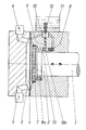
- the piston diaphragm pump shown has a displacement piston 1, which is oscillated back and forth in a piston working space 2 completely filled with hydraulic medium.
- the membrane 4 arranged between the delivery chamber 3 and the piston working chamber 2 thereby executes a membrane stroke corresponding to the piston stroke volume.
- the liquid to be pumped flows into the delivery chamber 3 via the suction valve 5 and is expelled via the pressure valve 6 during the pressure stroke.
- a support plate 7 which, although freely movable, has a security against falling out in the direction of the membrane 4.
- a plurality of springs 8a which are able to exert pressure on the support plate 7 in the direction against the membrane 4, act on the circumference of the support plate 7.
- a control tappet 13 also acts, which is provided with a conical recess 13a.
- the control plunger 13 is under the pressure of a spring 8 with direction of action against the support plate 7.
- a tumbler 9 engages essentially perpendicularly thereto, which is connected to the closing body 10 of the valve 12 at the opposite end.
- the length of the tumbler 9 is dimensioned such that the valve 12 is held in its closed position when it contacts the outer region of the circumferential rotation 13a of the control plunger 13. so that no hydraulic medium can flow into the piston working space from the reservoir 11. This is the normal position of the arrangement.
- the diaphragm 4 reaches the support plate 7 and moves it against the pressure of the springs 8a in the direction of the piston working chamber against the spring-loaded Control plunger 13.
- the control plunger 13 now resting on the support plate 7 moves in a forced manner against the spring force 8 in the same direction, so that the tumbler 9 slides on the conical circumferential recess 13a of the control plunger 13.
- the closing body 10 of the refill valve 12 is released.
- the refill valve 12 opens as a result of the negative pressure prevailing in the piston work chamber and allows hydraulic medium to flow into the piston work chamber from the reservoir 11.
- the membrane 4 and the support plate 7 move under the pressure of the springs 8 and 8a in the direction of the front space 3.
- the control plunger 13 is held in engagement with the support plate 7 by the pressure of the spring 8 and accordingly carries out the same movement .
- the tumbler slides upwards along the conical circumferential recess 13a until it is supported again by the outer circumferential region of the control plunger 13. This in turn locks the closing body 10 in the closed position of the valve 12.
- the spring shown on the valve 12 only serves to prevent the closing body 10 from falling, but without exerting any significant closing force on the valve.
- a piston diaphragm pump was thus created which advantageously overcomes the disadvantages mentioned at the outset.
Landscapes
- Engineering & Computer Science (AREA)
- Mechanical Engineering (AREA)
- General Engineering & Computer Science (AREA)
- Reciprocating Pumps (AREA)
Priority Applications (5)
| Application Number | Priority Date | Filing Date | Title |
|---|---|---|---|
| AT82100833T ATE10533T1 (de) | 1982-02-05 | 1982-02-05 | Kolbenmembranpumpe. |
| EP82100833A EP0085725B1 (de) | 1982-02-05 | 1982-02-05 | Kolbenmembranpumpe |
| DE8282100833T DE3261319D1 (en) | 1982-02-05 | 1982-02-05 | Piston-driven diaphragm pump |
| JP57058962A JPS58138286A (ja) | 1982-02-05 | 1982-04-08 | ピストン膜ポンプ |
| US06/377,573 US4465438A (en) | 1982-02-05 | 1982-05-12 | Piston diaphragm pump |
Applications Claiming Priority (1)
| Application Number | Priority Date | Filing Date | Title |
|---|---|---|---|
| EP82100833A EP0085725B1 (de) | 1982-02-05 | 1982-02-05 | Kolbenmembranpumpe |
Publications (2)
| Publication Number | Publication Date |
|---|---|
| EP0085725A1 EP0085725A1 (de) | 1983-08-17 |
| EP0085725B1 true EP0085725B1 (de) | 1984-11-28 |
Family
ID=8188859
Family Applications (1)
| Application Number | Title | Priority Date | Filing Date |
|---|---|---|---|
| EP82100833A Expired EP0085725B1 (de) | 1982-02-05 | 1982-02-05 | Kolbenmembranpumpe |
Country Status (5)
| Country | Link |
|---|---|
| US (1) | US4465438A (enExample) |
| EP (1) | EP0085725B1 (enExample) |
| JP (1) | JPS58138286A (enExample) |
| AT (1) | ATE10533T1 (enExample) |
| DE (1) | DE3261319D1 (enExample) |
Families Citing this family (32)
| Publication number | Priority date | Publication date | Assignee | Title |
|---|---|---|---|---|
| DE2843054C2 (de) * | 1978-10-03 | 1983-07-14 | Bran & Lübbe GmbH, 2000 Norderstedt | Kolbenmembranpumpe |
| DE3414006C2 (de) * | 1984-04-13 | 1986-03-06 | Bran & Lübbe GmbH, 2000 Norderstedt | Kolbenmembranpumpe |
| DE3446952A1 (de) * | 1984-12-21 | 1986-07-10 | Lewa Herbert Ott Gmbh + Co, 7250 Leonberg | Membranpumpe mit umlaufspuelung |
| CA1302782C (en) * | 1986-02-18 | 1992-06-09 | Viljo K. Valavaara | Rotary pressure intensifier |
| US4734013A (en) * | 1986-02-18 | 1988-03-29 | V-Tech Industries Inc. | Rotary pressure intensifier |
| DE3907735A1 (de) * | 1989-03-10 | 1990-09-20 | Bran & Luebbe | Membranpumpe mit freischwingender metallmembran |
| US5262068A (en) * | 1991-05-17 | 1993-11-16 | Millipore Corporation | Integrated system for filtering and dispensing fluid having fill, dispense and bubble purge strokes |
| US5288214A (en) * | 1991-09-30 | 1994-02-22 | Toshio Fukuda | Micropump |
| NZ261517A (en) * | 1993-01-19 | 1997-02-24 | Baxter Int | Multiple chamber container: openable valve in dividing seal |
| US5713878A (en) * | 1995-06-07 | 1998-02-03 | Surgi-Jet Corporation | Hand tightenable high pressure connector |
| US5871462A (en) * | 1995-06-07 | 1999-02-16 | Hydrocision, Inc. | Method for using a fluid jet cutting system |
| US6216573B1 (en) | 1995-06-07 | 2001-04-17 | Hydrocision, Inc. | Fluid jet cutting system |
| US5944686A (en) * | 1995-06-07 | 1999-08-31 | Hydrocision, Inc. | Instrument for creating a fluid jet |
| DE69732802T2 (de) * | 1996-06-07 | 2006-04-06 | Hydro Leduc | Flüssigkeitshochdruckpumpe |
| JP4372346B2 (ja) * | 1998-02-17 | 2009-11-25 | 日機装株式会社 | ダイアフラムポンプ |
| DE19826610A1 (de) * | 1998-06-16 | 1999-12-23 | Bran & Luebbe | Membranpumpe und Vorrichtung zur Steuerung derselben |
| FR2794813B1 (fr) | 1999-06-08 | 2001-09-21 | Peugeot Citroen Automobiles Sa | Pompe a haute pression a bouchon de remplissage perfectionne |
| RU2171398C1 (ru) * | 1999-11-17 | 2001-07-27 | Агапов Валерий Ибрагимович | Насос дозировочный мембранный гидроприводной |
| US20020176788A1 (en) * | 2001-04-27 | 2002-11-28 | Moutafis Timothy E. | High pressure pumping cartridges for medical and surgical pumping and infusion applications |
| CA2493238C (en) * | 2001-08-08 | 2007-10-23 | Hydrocision, Inc. | Medical device with high pressure quick disconnect handpiece |
| RU2238526C1 (ru) * | 2003-01-16 | 2004-10-20 | Общество с ограниченной ответственностью фирма "Саратовгазприборавтоматика" | Дозирующее устройство |
| RU2281415C2 (ru) * | 2004-06-28 | 2006-08-10 | Игорь Эдуардович Власов | Способ перекачивания жидкостных многофазных составов с нормативным давлением - власова и.э. |
| RU2271518C1 (ru) * | 2004-08-23 | 2006-03-10 | Общество с ограниченной ответственностью фирма "Саратовгазприборавтоматика" | Дозирующее устройство |
| JP4526350B2 (ja) * | 2004-10-29 | 2010-08-18 | シーケーディ株式会社 | 薬液供給用ポンプ |
| RU2315200C1 (ru) * | 2006-04-17 | 2008-01-20 | Наиль Минрахманович Нуртдинов | Блок дозированной подачи жидкости |
| DE102006062960B3 (de) | 2006-09-04 | 2018-11-29 | Spx Flow Technology Norderstedt Gmbh | Pumpenvorrichtung |
| DE102006041420A1 (de) | 2006-09-04 | 2008-03-20 | Bran + Luebbe Gmbh | Pumpenvorrichtung |
| EP2154371B1 (de) * | 2008-08-14 | 2018-09-19 | Bran + Lübbe GmbH | Pumpenvorrichtung |
| CN105332900B (zh) * | 2015-11-24 | 2017-12-08 | 杭州大潮石化设备有限公司 | 一种具有斜拉式可控补油结构的液压隔膜泵 |
| CN108119344B (zh) * | 2018-02-10 | 2024-06-04 | 台州信溢农业机械有限公司 | 一种具有阻尼功能的自动控制电动隔膜泵 |
| CN111502976B (zh) * | 2020-04-15 | 2024-06-18 | 陕西航天动力高科技股份有限公司 | 一种隔膜泵用补油控制装置 |
| DE202021106223U1 (de) * | 2021-11-15 | 2021-11-19 | Feluwa Pumpen Gmbh | Membrankolbenpumpe |
Family Cites Families (6)
| Publication number | Priority date | Publication date | Assignee | Title |
|---|---|---|---|---|
| DE68510C (de) * | G. leonhardt in 6 Damrak, Amsterdam | Fafs- oder Absperrhahn | ||
| FR1168708A (fr) * | 1957-02-28 | 1958-12-15 | Manuf Comtoise De Decolletage | Perfectionnements aux robinets à gaz du type à membrane |
| DE7303301U (de) * | 1973-01-30 | 1974-04-04 | Feluwa Schlesiger & Co Kg | Membran-Kolbenpumpe |
| JPS5420410A (en) * | 1977-07-15 | 1979-02-15 | Tsuneo Aoki | Diaphragm type fluid pressure feeder |
| DE2843054C2 (de) * | 1978-10-03 | 1983-07-14 | Bran & Lübbe GmbH, 2000 Norderstedt | Kolbenmembranpumpe |
| FR2492473B1 (fr) * | 1980-10-17 | 1985-06-28 | Milton Roy Dosapro | Pompe a membrane a compensation dans la chambre hydraulique de commande |
-
1982
- 1982-02-05 DE DE8282100833T patent/DE3261319D1/de not_active Expired
- 1982-02-05 AT AT82100833T patent/ATE10533T1/de not_active IP Right Cessation
- 1982-02-05 EP EP82100833A patent/EP0085725B1/de not_active Expired
- 1982-04-08 JP JP57058962A patent/JPS58138286A/ja active Granted
- 1982-05-12 US US06/377,573 patent/US4465438A/en not_active Expired - Lifetime
Also Published As
| Publication number | Publication date |
|---|---|
| US4465438A (en) | 1984-08-14 |
| JPS6358267B2 (enExample) | 1988-11-15 |
| EP0085725A1 (de) | 1983-08-17 |
| ATE10533T1 (de) | 1984-12-15 |
| JPS58138286A (ja) | 1983-08-17 |
| DE3261319D1 (en) | 1985-01-10 |
Similar Documents
| Publication | Publication Date | Title |
|---|---|---|
| EP0085725A1 (de) | Kolbenmembranpumpe | |
| EP0970309B1 (de) | Radialkolbenpumpe zur kraftstoffhochdruckversorgung | |
| DE3111065C2 (enExample) | ||
| DE2508382C2 (de) | Dämpfungsvorrichtung für automatische Maschinenfeuerwaffen | |
| DE69004667T2 (de) | Selbstumsteuernde kolbenpumpe mit hydraulischer übertragung des umkehrsignals. | |
| DE3542926C2 (enExample) | ||
| DE1948491A1 (de) | Verdichterventil mit einer Einrichtung zur Liefermengenregelung | |
| DE2258593A1 (de) | Druckgasbetaetigter zylinder mit hydraulischer kraftverstaerkung | |
| DE2909685A1 (de) | Hydraulischer kraftverstaerker | |
| DE2157347A1 (de) | Ventil, insbesondere für hydraulisch betätigbare Kraftfahrzeugbremsanlagen | |
| DE2123263C2 (de) | Hydraulischer Antrieb für Eilvorlauf, Arbeitshub und Eilrücklauf | |
| DE1752761C3 (de) | Überlastsicherung für eine Vorrichtung zur Herstellung nahtloser becherförmiger Behälter durch Ziehen | |
| DE2336211C3 (de) | Einfach wirkender pneumatischer Arbeitszylinder | |
| DE2819822C2 (de) | Hydraulische Feder | |
| EP3324064A1 (de) | Servoantrieb für eine reibungskupplung | |
| DE2713691C2 (enExample) | ||
| DE3828274A1 (de) | Hydraulikpumpe | |
| DE2732164A1 (de) | Hydraulisch angetriebene schlagvorrichtung | |
| DE3326793C2 (de) | Schieberventil mit zwei in der zylindrischen Bohrung eines Ventilgehäuses axial versetzt gegeneinander angeordneten Kolben | |
| DE1777423C2 (de) | Hydropneumatischer Spannzylinder | |
| DE2440219C3 (de) | Hydraulischer Arbeitszylinder für die Formschließvorrichtung einer Kunststoff-Spritzgießmaschine | |
| DE2504854C2 (de) | Radialkolbenpumpe | |
| DE2436808C2 (de) | Stufenhauptzylinder | |
| DE203567C (enExample) | ||
| DE1777424C2 (de) | Hydropneumatischer Spannzylinder |
Legal Events
| Date | Code | Title | Description |
|---|---|---|---|
| PUAI | Public reference made under article 153(3) epc to a published international application that has entered the european phase |
Free format text: ORIGINAL CODE: 0009012 |
|
| 17P | Request for examination filed |
Effective date: 19830329 |
|
| AK | Designated contracting states |
Designated state(s): AT BE CH DE FR GB IT LI LU NL SE |
|
| ITF | It: translation for a ep patent filed | ||
| GRAA | (expected) grant |
Free format text: ORIGINAL CODE: 0009210 |
|
| AK | Designated contracting states |
Designated state(s): AT BE CH DE FR GB IT LI LU NL SE |
|
| REF | Corresponds to: |
Ref document number: 10533 Country of ref document: AT Date of ref document: 19841215 Kind code of ref document: T |
|
| REF | Corresponds to: |
Ref document number: 3261319 Country of ref document: DE Date of ref document: 19850110 |
|
| ET | Fr: translation filed | ||
| PG25 | Lapsed in a contracting state [announced via postgrant information from national office to epo] |
Ref country code: LU Free format text: LAPSE BECAUSE OF NON-PAYMENT OF DUE FEES Effective date: 19850228 |
|
| PLBE | No opposition filed within time limit |
Free format text: ORIGINAL CODE: 0009261 |
|
| STAA | Information on the status of an ep patent application or granted ep patent |
Free format text: STATUS: NO OPPOSITION FILED WITHIN TIME LIMIT |
|
| 26N | No opposition filed | ||
| PGFP | Annual fee paid to national office [announced via postgrant information from national office to epo] |
Ref country code: LU Payment date: 19860404 Year of fee payment: 5 |
|
| BERE | Be: lapsed |
Owner name: BRAN & LUBBE G.M.B.H. Effective date: 19870228 |
|
| PG25 | Lapsed in a contracting state [announced via postgrant information from national office to epo] |
Ref country code: BE Effective date: 19890228 |
|
| ITTA | It: last paid annual fee | ||
| PGFP | Annual fee paid to national office [announced via postgrant information from national office to epo] |
Ref country code: SE Payment date: 19940110 Year of fee payment: 13 |
|
| PGFP | Annual fee paid to national office [announced via postgrant information from national office to epo] |
Ref country code: AT Payment date: 19940222 Year of fee payment: 13 |
|
| PGFP | Annual fee paid to national office [announced via postgrant information from national office to epo] |
Ref country code: NL Payment date: 19940228 Year of fee payment: 13 |
|
| PGFP | Annual fee paid to national office [announced via postgrant information from national office to epo] |
Ref country code: CH Payment date: 19940407 Year of fee payment: 13 |
|
| EAL | Se: european patent in force in sweden |
Ref document number: 82100833.1 |
|
| PG25 | Lapsed in a contracting state [announced via postgrant information from national office to epo] |
Ref country code: AT Effective date: 19950205 |
|
| PG25 | Lapsed in a contracting state [announced via postgrant information from national office to epo] |
Ref country code: SE Effective date: 19950206 |
|
| PG25 | Lapsed in a contracting state [announced via postgrant information from national office to epo] |
Ref country code: LI Effective date: 19950228 Ref country code: CH Effective date: 19950228 |
|
| PG25 | Lapsed in a contracting state [announced via postgrant information from national office to epo] |
Ref country code: NL Effective date: 19950901 |
|
| NLV4 | Nl: lapsed or anulled due to non-payment of the annual fee |
Effective date: 19950901 |
|
| EUG | Se: european patent has lapsed |
Ref document number: 82100833.1 |
|
| PGFP | Annual fee paid to national office [announced via postgrant information from national office to epo] |
Ref country code: GB Payment date: 20000110 Year of fee payment: 19 |
|
| PGFP | Annual fee paid to national office [announced via postgrant information from national office to epo] |
Ref country code: FR Payment date: 20000118 Year of fee payment: 19 |
|
| PGFP | Annual fee paid to national office [announced via postgrant information from national office to epo] |
Ref country code: DE Payment date: 20000425 Year of fee payment: 19 |
|
| PG25 | Lapsed in a contracting state [announced via postgrant information from national office to epo] |
Ref country code: GB Free format text: LAPSE BECAUSE OF NON-PAYMENT OF DUE FEES Effective date: 20010205 |
|
| GBPC | Gb: european patent ceased through non-payment of renewal fee |
Effective date: 20010205 |
|
| PG25 | Lapsed in a contracting state [announced via postgrant information from national office to epo] |
Ref country code: FR Free format text: LAPSE BECAUSE OF NON-PAYMENT OF DUE FEES Effective date: 20011031 |
|
| REG | Reference to a national code |
Ref country code: FR Ref legal event code: ST |
|
| PG25 | Lapsed in a contracting state [announced via postgrant information from national office to epo] |
Ref country code: DE Free format text: LAPSE BECAUSE OF NON-PAYMENT OF DUE FEES Effective date: 20011201 |