EP0084765A1 - Dispositif pour enrouler des barrages flottants, en particulier des barrages auto-expansibles - Google Patents
Dispositif pour enrouler des barrages flottants, en particulier des barrages auto-expansibles Download PDFInfo
- Publication number
- EP0084765A1 EP0084765A1 EP82850264A EP82850264A EP0084765A1 EP 0084765 A1 EP0084765 A1 EP 0084765A1 EP 82850264 A EP82850264 A EP 82850264A EP 82850264 A EP82850264 A EP 82850264A EP 0084765 A1 EP0084765 A1 EP 0084765A1
- Authority
- EP
- European Patent Office
- Prior art keywords
- boom
- rollers
- platform
- winding
- feed roller
- Prior art date
- Legal status (The legal status is an assumption and is not a legal conclusion. Google has not performed a legal analysis and makes no representation as to the accuracy of the status listed.)
- Granted
Links
Images


Classifications
-
- E—FIXED CONSTRUCTIONS
- E02—HYDRAULIC ENGINEERING; FOUNDATIONS; SOIL SHIFTING
- E02B—HYDRAULIC ENGINEERING
- E02B15/00—Cleaning or keeping clear the surface of open water; Apparatus therefor
- E02B15/04—Devices for cleaning or keeping clear the surface of open water from oil or like floating materials by separating or removing these materials
- E02B15/08—Devices for reducing the polluted area with or without additional devices for removing the material
- E02B15/0814—Devices for reducing the polluted area with or without additional devices for removing the material with underwater curtains
-
- Y—GENERAL TAGGING OF NEW TECHNOLOGICAL DEVELOPMENTS; GENERAL TAGGING OF CROSS-SECTIONAL TECHNOLOGIES SPANNING OVER SEVERAL SECTIONS OF THE IPC; TECHNICAL SUBJECTS COVERED BY FORMER USPC CROSS-REFERENCE ART COLLECTIONS [XRACs] AND DIGESTS
- Y02—TECHNOLOGIES OR APPLICATIONS FOR MITIGATION OR ADAPTATION AGAINST CLIMATE CHANGE
- Y02A—TECHNOLOGIES FOR ADAPTATION TO CLIMATE CHANGE
- Y02A20/00—Water conservation; Efficient water supply; Efficient water use
- Y02A20/20—Controlling water pollution; Waste water treatment
- Y02A20/204—Keeping clear the surface of open water from oil spills
-
- Y—GENERAL TAGGING OF NEW TECHNOLOGICAL DEVELOPMENTS; GENERAL TAGGING OF CROSS-SECTIONAL TECHNOLOGIES SPANNING OVER SEVERAL SECTIONS OF THE IPC; TECHNICAL SUBJECTS COVERED BY FORMER USPC CROSS-REFERENCE ART COLLECTIONS [XRACs] AND DIGESTS
- Y10—TECHNICAL SUBJECTS COVERED BY FORMER USPC
- Y10S—TECHNICAL SUBJECTS COVERED BY FORMER USPC CROSS-REFERENCE ART COLLECTIONS [XRACs] AND DIGESTS
- Y10S210/00—Liquid purification or separation
- Y10S210/918—Miscellaneous specific techniques
- Y10S210/922—Oil spill cleanup, e.g. bacterial
- Y10S210/923—Oil spill cleanup, e.g. bacterial using mechanical means, e.g. skimmers, pump
Definitions
- booms which in their floating bodies include expansion means for expanding after liberation to give the floating bodies their form.
- expansion means are suitably given a structure on the pantograph principle, e.g. as apparent from the Swedish Patent 348 249, which in readiness for laying out assumes a substantially flat shape.
- each oil-fighting station e.g. under the auspices of the coast guard organization, has its own set of booms in readiness, it is important that the booms are brought once again into a condition of readiness as soon as possible after a cleaning-up operation has been carried out, so that they can be used again, since an emergency can arise at very short notice.
- the present invention relates to an apparatus for bringing booms of the type mentioned above to a condition of readiness in a simple way, i.e. from a fully expanded condition to rolled-up shape, both the evacuation of air and collapse of the expansion means as well as reeling being done in one series of operations.
- the present invention proposes an apparatus solving the problems in question, when winding up booms about a vertical shaft or bobin.
- the inventive apparatus also provides compression of the floating bodies in conjunction with winding in a manner well suited for the purpose.
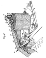
- the illustrated apparatus comprises a platform 1 provided with a circular recess 2, in which a turntable 3 is rotatably mounted in a manner not more closely illustrated.
- the turntable is adapted for driving via an unillustrated transmission by a motor 4 mounted on the platform 1.
- the turntable plate is provided with radial support ribs 5 in pairs, partly for reducing the friction of the boom edge against the plate, and partly to form grooves for the bundling tapes required for keeping together the subsequently reeled-up boom bundle.
- Four tubes 6 are mounted at the centre of the plate to form a winding bobin.
- the tubes 6 are mounted so that together they form a conical winding bobin, said tubes being attached to the plate 3 by bolted joints 7 running through the tubes a top plate 8 down through the tubes to the plate, in which they are threaded.
- the top plate 8 carries a central pin 9, removably accommodated in an arm ' 10 with an outer end 11 formed as an arrow head.
- This arrow head shape enables mountings for three cylindrical rollers 12, 13, 14, each of which is partially coated with a friction coating 15, 16, 17, e.g. of rubber.
- the rollers 12, 13, 14 are rotatable as illustrated by the arrow 18.
- the plate 3 and rollers 12, 13, 14 are not in any mutual driving relationship.
- a disc 19 is mounted with its plane at an angle to the surface of the platform 1. The mounting of this disc will be described in detail in conjunction with Figure 4.
- a further disc 21 is mounted in a bearing 20 at the centre of the disc 19, the disc 21 in turn carrying a structure comprising two arms 22 and 23, respectively carrying two members 25, 24 at their outer ends.
- the pairs of arms and members 22, 25 and 23, 24 each carry a side plate 26, 27, respectively provided with bearings 28 for a feed and arresting roller 29, having a frictional layer 30, e.g. of rubber, on its cylindrical surface.
- a feed and arresting roller 29 having a frictional layer 30, e.g. of rubber, on its cylindrical surface.
- the disc 19 is provided with a plurality of holes 25 for coaction with a locking pin passing through a hole 36 in the plate 21.
- the motor 4 is then started, causing the turntable to rotate in the direction illustrated by the arrow 38.
- the roller 29 will rotate in the direction of the arrow 39, and the rollers 12, 13, 14 in the direction of arrow 18.
- the rope is thus wound up on the tubes 6 and the boom is drawn in towards the roller 29.
- the boom 40 with its skirt portion 41 provided with chain at its bottom edge will run over the roller 29, rollers 12, 13, 14 and be reeled up on the tubes 6.
- the boom is of the type provided with expansion means 43, indicated by dashed lines, in the form of pantograph structures.
- expansion means 43 indicated by dashed lines
- the elongate floating body has a quadratic cross section in an expanded state.
- the expansion means of the boom are pressed together so that the boom is given a substantially flat shape.
- this compression takes place substantially about the rollers 12, 13, 14.
- the distance between the rolls 31 and 32 is set so that the floating body of the boom in a non-expanded state can be guided in between the rolls together with the skirt portion 41.
- the dis- stance between the rolls is such that the skirt portion is crumpled together and thus comes against the frictional surface 30 of the roller 29 with great friction.
- the expansion means will tend to collapse.
- the boom By applying braking force to the roller 29, the boom will be stretched over the rollers 12, 13, 14, stretching during the continued reeling-up of the boom will be so heavy that the expansion means are flattened out.
- the boom With the aid of the roller 29 the boom is guided in so that the body of the boom with the expansion means will arrive at approximately the upper portion of the rollers 12, 13, 14, which is provided with friction coating.
- the roller 29 must occasionally take up considerable forces if the plant is used on a so-called offshore platform. In such cases the lifting height is about 30 meters, and if a sea boom is used, which weighs about 12 kg per meter the total weight during the lift will be about 360 kg. This means that no braking force will generally be necessary on the roller 29, and when the boom rolls in over the roller the expansion means 43 will already be flattened out at this stage. As will be seen, it is of importance that the roller 29 can be adjusted to suit the different directions occurring during reeling in the boom. Binding due to wedging action will otherwise easily occur at the rolls 31 or 32.
- the disc 19 is pivotably attached to the platform, as illustrated in Figure 4.
- This attachment is adapted such that a substantially rectangular bracket 44 projects out from the platform 1 and is provided at its free end with a through shaft 45, on which are mounted two lugs 46, 47 attached to the side of the disc 19 facing the platform.
- the platform is also provided with a lug 48 in which is pivotably mounted a means 49 having its other end pivotably mounted on the disc 19.
- This means 49 may be such as a turnbuckle.
- the disc 19 can be caused to move in the directions of the double arrow 50, for allowing the roller to assume different levels in relation to the platform 1.
- the movement of the boom round the rollers 12, 13, 14 can be relatively easily guided in this way, such that the boom in its flattened condition will be correctly advanced round the tubes 6, for coming at the right approach height relative the turntable plate 3.
- both the angular attitude of the roller 29, by the rotation of the disc 21 in relation to the disc 19, as well as the pivoting about the shaft 45 can be accomplished by hydraulic means, electric motors or other power driven means. What has been shown in the Figures is only to be regarded as simple solutions to illustrate the basic principle for setting the attitude of the roller 29.
- the roller 29 can be braked by braking means known per se, and to avoid unnecessary complications braking means have not been illustrated in the figures.
Applications Claiming Priority (2)
| Application Number | Priority Date | Filing Date | Title |
|---|---|---|---|
| SE8107776 | 1981-12-23 | ||
| SE8107776A SE429143B (sv) | 1981-12-23 | 1981-12-23 | Anordning vid upplindning av lensor, serskilt s k sjelvexpanderande lensor |
Publications (2)
| Publication Number | Publication Date |
|---|---|
| EP0084765A1 true EP0084765A1 (fr) | 1983-08-03 |
| EP0084765B1 EP0084765B1 (fr) | 1985-10-16 |
Family
ID=20345372
Family Applications (1)
| Application Number | Title | Priority Date | Filing Date |
|---|---|---|---|
| EP82850264A Expired EP0084765B1 (fr) | 1981-12-23 | 1982-12-21 | Dispositif pour enrouler des barrages flottants, en particulier des barrages auto-expansibles |
Country Status (11)
| Country | Link |
|---|---|
| US (1) | US4480800A (fr) |
| EP (1) | EP0084765B1 (fr) |
| JP (1) | JPS58160425A (fr) |
| KR (1) | KR910000984B1 (fr) |
| AU (1) | AU549735B2 (fr) |
| CA (1) | CA1182103A (fr) |
| DE (1) | DE3266966D1 (fr) |
| DK (1) | DK153958C (fr) |
| FI (1) | FI71595C (fr) |
| NO (1) | NO152018C (fr) |
| SE (1) | SE429143B (fr) |
Cited By (1)
| Publication number | Priority date | Publication date | Assignee | Title |
|---|---|---|---|---|
| WO1997007291A1 (fr) * | 1995-08-17 | 1997-02-27 | Nofi Tromsø A/S | Procede d'empaquetage de barrages flottants et sac associe |
Families Citing this family (27)
| Publication number | Priority date | Publication date | Assignee | Title |
|---|---|---|---|---|
| DE3670666D1 (de) * | 1985-06-28 | 1990-05-31 | Cousins Neville Lawrence | Zurueckziehbare decke. |
| US4836920A (en) * | 1988-07-20 | 1989-06-06 | Miller Jr Joseph E | Recoil web pool skimmer |
| US4964758A (en) * | 1989-10-17 | 1990-10-23 | Anatol Pekelny | Floating oil enclosure barriers an dispensing means aboard an oil tanker for discharging without the aid of surface vessels |
| US5451325A (en) * | 1989-12-06 | 1995-09-19 | Herkenberg; Wolf | Method for the removal of oil from oil spills |
| SE465277B (sv) * | 1989-12-20 | 1991-08-19 | Roto Mekan Ab | Anordning vid laensor |
| US5086988A (en) * | 1990-03-01 | 1992-02-11 | Lapoint David A | Car cover deployment and storage system |
| US5060589A (en) * | 1990-07-16 | 1991-10-29 | Winckelmann Emil V | System for alleviating the effects of oil tanker oil spills |
| US5201607A (en) * | 1990-08-23 | 1993-04-13 | Whidden Jr Malcolm B | Value assembly for inflating and deflating chambers of a floatable boom |
| US5253953A (en) * | 1990-08-23 | 1993-10-19 | Whidden Jr Malcolm B | Boom for containing oil spills |
| US5143479A (en) * | 1990-08-23 | 1992-09-01 | Whidden Jr Malcolm B | Carrier vessel especially suitable for oil spill containment |
| US5087152A (en) * | 1990-08-23 | 1992-02-11 | Whidden Malcolm B | Boom for containing oil spills and methods of deploying and retrieving same |
| SE9401289D0 (sv) * | 1994-04-15 | 1994-04-15 | Mkh Konsult | Anordning för länsor |
| SE503232C2 (sv) * | 1994-11-18 | 1996-04-22 | Trelleborg Ind Ab | Oljelänsa för snabbutläggning |
| US7314141B1 (en) * | 1998-08-06 | 2008-01-01 | Paul Hedley Day | Folding belt filter |
| JP2000079389A (ja) * | 1998-09-07 | 2000-03-21 | Trp:Kk | 水面上の浮遊物除去回収処理方法およびその処理装置 |
| FR2804978B1 (fr) * | 2000-01-27 | 2004-08-20 | Francois Faraud | Barrage antipollution par confinement des nappes de produits polluants flottant a la surface de l'eau |
| US6718726B1 (en) * | 2001-10-09 | 2004-04-13 | Dreamwell Ltd. | Method and apparatus for storing and transporting strings of pocketed coils |
| US7998344B2 (en) * | 2002-08-12 | 2011-08-16 | Miller Robert L | Methods and apparatuses for filtering water from oil and gas wells |
| US7074337B2 (en) * | 2002-08-12 | 2006-07-11 | Jeffrey S. Melcher | Methods and apparatuses for filtering water |
| US7828494B1 (en) | 2008-06-05 | 2010-11-09 | 6937381 Canada Ltd. | Buoy assembly |
| FI20080607L (fi) * | 2008-11-06 | 2010-05-07 | Lars Ingram Lundin | Öljynkeruujärjestelmän ankkurointijärjestelmä |
| US9206575B2 (en) | 2010-06-25 | 2015-12-08 | Michael T. D. Miller | Onboard oil containment system |
| US9221650B1 (en) | 2010-07-02 | 2015-12-29 | Charles Fuselier | Apparatus and method for the recovery of oil absorbent booms |
| US9216879B1 (en) | 2010-09-01 | 2015-12-22 | Charles Fuselier | Automated oil containment boom recovery device |
| US20120163915A1 (en) * | 2010-10-22 | 2012-06-28 | Oilcling Corporation | Apparatus and method for containing and recovering from oil spills |
| US9523210B2 (en) * | 2013-01-11 | 2016-12-20 | Calvin Hargis | Pool skimmer |
| US10611502B2 (en) | 2016-10-20 | 2020-04-07 | Roccor, Llc | Precision deployment devices, systems, and methods |
Citations (7)
| Publication number | Priority date | Publication date | Assignee | Title |
|---|---|---|---|---|
| SE348249B (fr) * | 1971-01-27 | 1972-08-28 | Sanera Projecting Ab | |
| DE2363500A1 (de) * | 1972-12-26 | 1974-06-27 | Pneumatiques Caoutchouc Mfg | Schwimmende sperren |
| DE2106851B2 (de) * | 1971-02-13 | 1976-03-11 | E.F. Kress Söhne, 4154 Tonisvorst | Vorrichtung zum spiraligen auf- und abnadeln einer insbesondere textilen warenbahn |
| US3971220A (en) * | 1973-02-23 | 1976-07-27 | Mitsubishi Denki Kabushiki Kaisha | Oil fence |
| DE2619315B2 (de) * | 1975-05-01 | 1977-06-16 | Bridgestone Tire Co. Ltd., Tokio | Vorrichtung zum einholen und ausbringen einer oelsperre |
| US4117991A (en) * | 1977-03-09 | 1978-10-03 | Johnson Roy E | Hose winding mechanism |
| SE424204B (sv) * | 1978-10-30 | 1982-07-05 | Sanera Projecting Ab | Anordning vid upplindning av lensor, serskilt sk sjelvexpanderande lensor |
Family Cites Families (8)
| Publication number | Priority date | Publication date | Assignee | Title |
|---|---|---|---|---|
| US3539013A (en) * | 1968-06-24 | 1970-11-10 | Millard F Smith | Oil collection boom |
| US3563036A (en) * | 1969-09-02 | 1971-02-16 | Millard F Smith | Inflatable floating booms |
| US4089178A (en) * | 1973-02-23 | 1978-05-16 | Mitsubishi Denki Kabushiki Kaisha | Apparatus for deploying and taking up an oil fence |
| JPS5339632A (en) * | 1976-09-24 | 1978-04-11 | Mitsubishi Heavy Ind Ltd | Device for accommodating and extending oil fence |
| GB1554737A (en) * | 1976-10-20 | 1979-10-31 | British Petroleum Co | Oil control system |
| JPS5493586A (en) * | 1977-12-28 | 1979-07-24 | Niigata Eng Co Ltd | Generator driving gear attached to marine main engine |
| US4311109A (en) * | 1979-03-06 | 1982-01-19 | The British Petroleum Company Limited | Fairlead |
| JPS613871Y2 (fr) * | 1979-08-09 | 1986-02-06 |
-
1981
- 1981-12-23 SE SE8107776A patent/SE429143B/sv not_active IP Right Cessation
-
1982
- 1982-12-13 FI FI824274A patent/FI71595C/fi not_active IP Right Cessation
- 1982-12-16 US US06/450,498 patent/US4480800A/en not_active Expired - Lifetime
- 1982-12-21 DE DE8282850264T patent/DE3266966D1/de not_active Expired
- 1982-12-21 EP EP82850264A patent/EP0084765B1/fr not_active Expired
- 1982-12-21 CA CA000418263A patent/CA1182103A/fr not_active Expired
- 1982-12-22 AU AU91853/82A patent/AU549735B2/en not_active Ceased
- 1982-12-22 DK DK568982A patent/DK153958C/da not_active IP Right Cessation
- 1982-12-22 NO NO824338A patent/NO152018C/no unknown
- 1982-12-22 KR KR8205741A patent/KR910000984B1/ko active
- 1982-12-23 JP JP57225109A patent/JPS58160425A/ja active Granted
Patent Citations (7)
| Publication number | Priority date | Publication date | Assignee | Title |
|---|---|---|---|---|
| SE348249B (fr) * | 1971-01-27 | 1972-08-28 | Sanera Projecting Ab | |
| DE2106851B2 (de) * | 1971-02-13 | 1976-03-11 | E.F. Kress Söhne, 4154 Tonisvorst | Vorrichtung zum spiraligen auf- und abnadeln einer insbesondere textilen warenbahn |
| DE2363500A1 (de) * | 1972-12-26 | 1974-06-27 | Pneumatiques Caoutchouc Mfg | Schwimmende sperren |
| US3971220A (en) * | 1973-02-23 | 1976-07-27 | Mitsubishi Denki Kabushiki Kaisha | Oil fence |
| DE2619315B2 (de) * | 1975-05-01 | 1977-06-16 | Bridgestone Tire Co. Ltd., Tokio | Vorrichtung zum einholen und ausbringen einer oelsperre |
| US4117991A (en) * | 1977-03-09 | 1978-10-03 | Johnson Roy E | Hose winding mechanism |
| SE424204B (sv) * | 1978-10-30 | 1982-07-05 | Sanera Projecting Ab | Anordning vid upplindning av lensor, serskilt sk sjelvexpanderande lensor |
Cited By (1)
| Publication number | Priority date | Publication date | Assignee | Title |
|---|---|---|---|---|
| WO1997007291A1 (fr) * | 1995-08-17 | 1997-02-27 | Nofi Tromsø A/S | Procede d'empaquetage de barrages flottants et sac associe |
Also Published As
| Publication number | Publication date |
|---|---|
| AU549735B2 (en) | 1986-02-06 |
| JPS58160425A (ja) | 1983-09-22 |
| NO152018B (no) | 1985-04-09 |
| FI824274A0 (fi) | 1982-12-13 |
| SE8107776L (sv) | 1983-06-24 |
| FI71595C (fi) | 1987-01-19 |
| CA1182103A (fr) | 1985-02-05 |
| EP0084765B1 (fr) | 1985-10-16 |
| SE429143B (sv) | 1983-08-15 |
| KR840002938A (ko) | 1984-07-21 |
| DE3266966D1 (en) | 1985-11-21 |
| DK568982A (da) | 1983-06-24 |
| NO824338L (no) | 1983-06-24 |
| US4480800A (en) | 1984-11-06 |
| FI71595B (fi) | 1986-10-10 |
| NO152018C (no) | 1985-07-17 |
| DK153958C (da) | 1989-03-20 |
| AU9185382A (en) | 1983-06-30 |
| FI824274L (fi) | 1983-06-24 |
| KR910000984B1 (ko) | 1991-02-19 |
| DK153958B (da) | 1988-09-26 |
| JPH0362842B2 (fr) | 1991-09-27 |
Similar Documents
| Publication | Publication Date | Title |
|---|---|---|
| EP0084765B1 (fr) | Dispositif pour enrouler des barrages flottants, en particulier des barrages auto-expansibles | |
| US3965713A (en) | Method and apparatus for laying continuous pipe | |
| US3982402A (en) | Submarine pipeline laying vessel | |
| US4157023A (en) | Apparatus and method for laying pipelines | |
| US3383064A (en) | Rewinder for paper and the like | |
| US3980037A (en) | Apparatus for mooring ships | |
| CN214618151U (zh) | 一种市政工程管道安装装置 | |
| US4640469A (en) | System for rolling and unrolling a ground cover | |
| CN218642255U (zh) | 一种装配式建筑施工吊装装置 | |
| US3775985A (en) | Apparatus for laying submarine pipelines | |
| CN210333823U (zh) | 一种防缠绕钢筋放卷装置 | |
| CN214329178U (zh) | 雨水循环管道用安装结构 | |
| CN211945637U (zh) | 绳体结构释放组件 | |
| CA1142889A (fr) | Grue de type teleferique | |
| US3172544A (en) | Slack puller | |
| CN208576835U (zh) | 补偿链打包装置 | |
| JP2539339Y2 (ja) | 箱体起倒装置 | |
| US3983705A (en) | Apparatus for forming a bottom protection | |
| CN220787501U (zh) | 一种自动对边卷取装置 | |
| CN214003548U (zh) | 无纺布卷外包防潮膜的包装设备 | |
| JP2627391B2 (ja) | 高圧送電ケーブルの敷設装置 | |
| CN212756944U (zh) | 一种组合移动式消防水带收放器 | |
| SU1148926A1 (ru) | Устройство дл укладки вертикального противофильтрационного экрана из пленочного материала в траншею | |
| CN115028012A (zh) | 一种带有惯性抑制效果的电缆卷放设备 | |
| KR20230139172A (ko) | 해양용 매트 설치 장치 |
Legal Events
| Date | Code | Title | Description |
|---|---|---|---|
| PUAI | Public reference made under article 153(3) epc to a published international application that has entered the european phase |
Free format text: ORIGINAL CODE: 0009012 |
|
| AK | Designated contracting states |
Designated state(s): BE DE FR GB IT NL |
|
| 17P | Request for examination filed |
Effective date: 19831111 |
|
| ITF | It: translation for a ep patent filed |
Owner name: UFFICIO TECNICO ING. A. MANNUCCI |
|
| GRAA | (expected) grant |
Free format text: ORIGINAL CODE: 0009210 |
|
| AK | Designated contracting states |
Designated state(s): BE DE FR GB IT NL |
|
| ET | Fr: translation filed | ||
| REF | Corresponds to: |
Ref document number: 3266966 Country of ref document: DE Date of ref document: 19851121 |
|
| PLBE | No opposition filed within time limit |
Free format text: ORIGINAL CODE: 0009261 |
|
| STAA | Information on the status of an ep patent application or granted ep patent |
Free format text: STATUS: NO OPPOSITION FILED WITHIN TIME LIMIT |
|
| 26N | No opposition filed | ||
| ITTA | It: last paid annual fee | ||
| PGFP | Annual fee paid to national office [announced via postgrant information from national office to epo] |
Ref country code: DE Payment date: 19961213 Year of fee payment: 15 |
|
| PGFP | Annual fee paid to national office [announced via postgrant information from national office to epo] |
Ref country code: GB Payment date: 19971202 Year of fee payment: 16 |
|
| PGFP | Annual fee paid to national office [announced via postgrant information from national office to epo] |
Ref country code: FR Payment date: 19971211 Year of fee payment: 16 |
|
| PGFP | Annual fee paid to national office [announced via postgrant information from national office to epo] |
Ref country code: NL Payment date: 19971231 Year of fee payment: 16 |
|
| PGFP | Annual fee paid to national office [announced via postgrant information from national office to epo] |
Ref country code: BE Payment date: 19980115 Year of fee payment: 16 |
|
| PG25 | Lapsed in a contracting state [announced via postgrant information from national office to epo] |
Ref country code: DE Free format text: LAPSE BECAUSE OF NON-PAYMENT OF DUE FEES Effective date: 19980901 |
|
| PG25 | Lapsed in a contracting state [announced via postgrant information from national office to epo] |
Ref country code: GB Free format text: LAPSE BECAUSE OF NON-PAYMENT OF DUE FEES Effective date: 19981221 |
|
| PG25 | Lapsed in a contracting state [announced via postgrant information from national office to epo] |
Ref country code: BE Free format text: LAPSE BECAUSE OF NON-PAYMENT OF DUE FEES Effective date: 19981231 |
|
| BERE | Be: lapsed |
Owner name: SANERA PROJECTING A.B. Effective date: 19981231 |
|
| PG25 | Lapsed in a contracting state [announced via postgrant information from national office to epo] |
Ref country code: NL Free format text: LAPSE BECAUSE OF NON-PAYMENT OF DUE FEES Effective date: 19990701 |
|
| GBPC | Gb: european patent ceased through non-payment of renewal fee |
Effective date: 19981221 |
|
| PG25 | Lapsed in a contracting state [announced via postgrant information from national office to epo] |
Ref country code: FR Free format text: LAPSE BECAUSE OF NON-PAYMENT OF DUE FEES Effective date: 19990831 |
|
| NLV4 | Nl: lapsed or anulled due to non-payment of the annual fee |
Effective date: 19990701 |
|
| REG | Reference to a national code |
Ref country code: FR Ref legal event code: ST |