EP0084765A1 - Apparatus for reeling floating booms, particularly such as are self-expanding - Google Patents
Apparatus for reeling floating booms, particularly such as are self-expanding Download PDFInfo
- Publication number
- EP0084765A1 EP0084765A1 EP82850264A EP82850264A EP0084765A1 EP 0084765 A1 EP0084765 A1 EP 0084765A1 EP 82850264 A EP82850264 A EP 82850264A EP 82850264 A EP82850264 A EP 82850264A EP 0084765 A1 EP0084765 A1 EP 0084765A1
- Authority
- EP
- European Patent Office
- Prior art keywords
- boom
- rollers
- platform
- winding
- feed roller
- Prior art date
- Legal status (The legal status is an assumption and is not a legal conclusion. Google has not performed a legal analysis and makes no representation as to the accuracy of the status listed.)
- Granted
Links
Images


Classifications
-
- E—FIXED CONSTRUCTIONS
- E02—HYDRAULIC ENGINEERING; FOUNDATIONS; SOIL SHIFTING
- E02B—HYDRAULIC ENGINEERING
- E02B15/00—Cleaning or keeping clear the surface of open water; Apparatus therefor
- E02B15/04—Devices for cleaning or keeping clear the surface of open water from oil or like floating materials by separating or removing these materials
- E02B15/08—Devices for reducing the polluted area with or without additional devices for removing the material
- E02B15/0814—Devices for reducing the polluted area with or without additional devices for removing the material with underwater curtains
-
- Y—GENERAL TAGGING OF NEW TECHNOLOGICAL DEVELOPMENTS; GENERAL TAGGING OF CROSS-SECTIONAL TECHNOLOGIES SPANNING OVER SEVERAL SECTIONS OF THE IPC; TECHNICAL SUBJECTS COVERED BY FORMER USPC CROSS-REFERENCE ART COLLECTIONS [XRACs] AND DIGESTS
- Y02—TECHNOLOGIES OR APPLICATIONS FOR MITIGATION OR ADAPTATION AGAINST CLIMATE CHANGE
- Y02A—TECHNOLOGIES FOR ADAPTATION TO CLIMATE CHANGE
- Y02A20/00—Water conservation; Efficient water supply; Efficient water use
- Y02A20/20—Controlling water pollution; Waste water treatment
- Y02A20/204—Keeping clear the surface of open water from oil spills
-
- Y—GENERAL TAGGING OF NEW TECHNOLOGICAL DEVELOPMENTS; GENERAL TAGGING OF CROSS-SECTIONAL TECHNOLOGIES SPANNING OVER SEVERAL SECTIONS OF THE IPC; TECHNICAL SUBJECTS COVERED BY FORMER USPC CROSS-REFERENCE ART COLLECTIONS [XRACs] AND DIGESTS
- Y10—TECHNICAL SUBJECTS COVERED BY FORMER USPC
- Y10S—TECHNICAL SUBJECTS COVERED BY FORMER USPC CROSS-REFERENCE ART COLLECTIONS [XRACs] AND DIGESTS
- Y10S210/00—Liquid purification or separation
- Y10S210/918—Miscellaneous specific techniques
- Y10S210/922—Oil spill cleanup, e.g. bacterial
- Y10S210/923—Oil spill cleanup, e.g. bacterial using mechanical means, e.g. skimmers, pump
Definitions
- booms which in their floating bodies include expansion means for expanding after liberation to give the floating bodies their form.
- expansion means are suitably given a structure on the pantograph principle, e.g. as apparent from the Swedish Patent 348 249, which in readiness for laying out assumes a substantially flat shape.
- each oil-fighting station e.g. under the auspices of the coast guard organization, has its own set of booms in readiness, it is important that the booms are brought once again into a condition of readiness as soon as possible after a cleaning-up operation has been carried out, so that they can be used again, since an emergency can arise at very short notice.
- the present invention relates to an apparatus for bringing booms of the type mentioned above to a condition of readiness in a simple way, i.e. from a fully expanded condition to rolled-up shape, both the evacuation of air and collapse of the expansion means as well as reeling being done in one series of operations.
- the present invention proposes an apparatus solving the problems in question, when winding up booms about a vertical shaft or bobin.
- the inventive apparatus also provides compression of the floating bodies in conjunction with winding in a manner well suited for the purpose.
- the illustrated apparatus comprises a platform 1 provided with a circular recess 2, in which a turntable 3 is rotatably mounted in a manner not more closely illustrated.
- the turntable is adapted for driving via an unillustrated transmission by a motor 4 mounted on the platform 1.
- the turntable plate is provided with radial support ribs 5 in pairs, partly for reducing the friction of the boom edge against the plate, and partly to form grooves for the bundling tapes required for keeping together the subsequently reeled-up boom bundle.
- Four tubes 6 are mounted at the centre of the plate to form a winding bobin.
- the tubes 6 are mounted so that together they form a conical winding bobin, said tubes being attached to the plate 3 by bolted joints 7 running through the tubes a top plate 8 down through the tubes to the plate, in which they are threaded.
- the top plate 8 carries a central pin 9, removably accommodated in an arm ' 10 with an outer end 11 formed as an arrow head.
- This arrow head shape enables mountings for three cylindrical rollers 12, 13, 14, each of which is partially coated with a friction coating 15, 16, 17, e.g. of rubber.
- the rollers 12, 13, 14 are rotatable as illustrated by the arrow 18.
- the plate 3 and rollers 12, 13, 14 are not in any mutual driving relationship.
- a disc 19 is mounted with its plane at an angle to the surface of the platform 1. The mounting of this disc will be described in detail in conjunction with Figure 4.
- a further disc 21 is mounted in a bearing 20 at the centre of the disc 19, the disc 21 in turn carrying a structure comprising two arms 22 and 23, respectively carrying two members 25, 24 at their outer ends.
- the pairs of arms and members 22, 25 and 23, 24 each carry a side plate 26, 27, respectively provided with bearings 28 for a feed and arresting roller 29, having a frictional layer 30, e.g. of rubber, on its cylindrical surface.
- a feed and arresting roller 29 having a frictional layer 30, e.g. of rubber, on its cylindrical surface.
- the disc 19 is provided with a plurality of holes 25 for coaction with a locking pin passing through a hole 36 in the plate 21.
- the motor 4 is then started, causing the turntable to rotate in the direction illustrated by the arrow 38.
- the roller 29 will rotate in the direction of the arrow 39, and the rollers 12, 13, 14 in the direction of arrow 18.
- the rope is thus wound up on the tubes 6 and the boom is drawn in towards the roller 29.
- the boom 40 with its skirt portion 41 provided with chain at its bottom edge will run over the roller 29, rollers 12, 13, 14 and be reeled up on the tubes 6.
- the boom is of the type provided with expansion means 43, indicated by dashed lines, in the form of pantograph structures.
- expansion means 43 indicated by dashed lines
- the elongate floating body has a quadratic cross section in an expanded state.
- the expansion means of the boom are pressed together so that the boom is given a substantially flat shape.
- this compression takes place substantially about the rollers 12, 13, 14.
- the distance between the rolls 31 and 32 is set so that the floating body of the boom in a non-expanded state can be guided in between the rolls together with the skirt portion 41.
- the dis- stance between the rolls is such that the skirt portion is crumpled together and thus comes against the frictional surface 30 of the roller 29 with great friction.
- the expansion means will tend to collapse.
- the boom By applying braking force to the roller 29, the boom will be stretched over the rollers 12, 13, 14, stretching during the continued reeling-up of the boom will be so heavy that the expansion means are flattened out.
- the boom With the aid of the roller 29 the boom is guided in so that the body of the boom with the expansion means will arrive at approximately the upper portion of the rollers 12, 13, 14, which is provided with friction coating.
- the roller 29 must occasionally take up considerable forces if the plant is used on a so-called offshore platform. In such cases the lifting height is about 30 meters, and if a sea boom is used, which weighs about 12 kg per meter the total weight during the lift will be about 360 kg. This means that no braking force will generally be necessary on the roller 29, and when the boom rolls in over the roller the expansion means 43 will already be flattened out at this stage. As will be seen, it is of importance that the roller 29 can be adjusted to suit the different directions occurring during reeling in the boom. Binding due to wedging action will otherwise easily occur at the rolls 31 or 32.
- the disc 19 is pivotably attached to the platform, as illustrated in Figure 4.
- This attachment is adapted such that a substantially rectangular bracket 44 projects out from the platform 1 and is provided at its free end with a through shaft 45, on which are mounted two lugs 46, 47 attached to the side of the disc 19 facing the platform.
- the platform is also provided with a lug 48 in which is pivotably mounted a means 49 having its other end pivotably mounted on the disc 19.
- This means 49 may be such as a turnbuckle.
- the disc 19 can be caused to move in the directions of the double arrow 50, for allowing the roller to assume different levels in relation to the platform 1.
- the movement of the boom round the rollers 12, 13, 14 can be relatively easily guided in this way, such that the boom in its flattened condition will be correctly advanced round the tubes 6, for coming at the right approach height relative the turntable plate 3.
- both the angular attitude of the roller 29, by the rotation of the disc 21 in relation to the disc 19, as well as the pivoting about the shaft 45 can be accomplished by hydraulic means, electric motors or other power driven means. What has been shown in the Figures is only to be regarded as simple solutions to illustrate the basic principle for setting the attitude of the roller 29.
- the roller 29 can be braked by braking means known per se, and to avoid unnecessary complications braking means have not been illustrated in the figures.
Abstract
Description
- Today, it is usual in conjunction with oil-fighting efforts to use so-called self-expanding booms, i.e. booms which in their floating bodies include expansion means for expanding after liberation to give the floating bodies their form. Such means are suitably given a structure on the pantograph principle, e.g. as apparent from the Swedish Patent 348 249, which in readiness for laying out assumes a substantially flat shape.
- In practice it has been found that gathering together the expansion means and flattening the floating bodies after use is a relatively time-consuming procedure, independent of whether it is the intention to store the boom in a folded packaged condition or rolled-up. The air enclosed by the floating bodies must be evacuated in some way, simultaneously as the expansion means are brought into a flat state and kept in this state. Air evacuation has been done with the aid of vacuum cleaners or like means in some cases, while the expansion means have suitably been collapsed by hand.
- Since it is usual that each oil-fighting station, e.g. under the auspices of the coast guard organization, has its own set of booms in readiness, it is important that the booms are brought once again into a condition of readiness as soon as possible after a cleaning-up operation has been carried out, so that they can be used again, since an emergency can arise at very short notice.
- The present invention relates to an apparatus for bringing booms of the type mentioned above to a condition of readiness in a simple way, i.e. from a fully expanded condition to rolled-up shape, both the evacuation of air and collapse of the expansion means as well as reeling being done in one series of operations.
- In the Swedish Patent Application 7811245-5 there is proposed a reeling device for booms of the kind in question, which operates with a horizontal winding shaft. However, it has been found in practice that although this device functions very well, handling the boom after winding has caused certain problems. As will be appreciated, the fabric or so-called skirt hanging down from the floating body is provided with weights along its bottom edge, for keeping the boom in its proper floating position and ensuring the necessary isolation of the oil patch which is to be cleaned up. It is usual to sew a chain of suitable size into the bottom edge of the skirt, and this chain then serves as a stiffening element as well as a weight. When a boom is wound up into a round bundle, the lower edge of the skirt with its chain will of necessity be reeled up along one side of the bundle, which means that the weight on this side will be large. Handling problems in conjunction with lifting and transporting the bundle will thus be considerable. Proposals have therefore been made to wind up the boom about a vertical axle so that the chain portion comes at the bottom of the ready bundle. The problem appears to be simple to solve, but practical tests have shown that the device carrying out the winding must have certain characteristics if the desired winding result is obtained.
- The present invention proposes an apparatus solving the problems in question, when winding up booms about a vertical shaft or bobin. The inventive apparatus also provides compression of the floating bodies in conjunction with winding in a manner well suited for the purpose.
- What is characterizing for the present invention will be apparent from the following claims.
- The invention will now be described in detail with reference to the appended drawings illustrating an embodiment thereof.
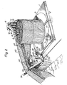
- Figure 1 is a perspective view of an apparatus in accordance with the invention.
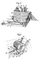
- Figure 2 illustrates the same apparatus as a boom is being reeled.
- Figure 3 illustrates in perspective a view of the same operation as in Figure 2 but from another point of view.
- Figure 4 is a perspective view of detail of the the input and arresting roller structure.
- Figure 5 is a perspective view of raising the ready-wound boom bundle.
- The illustrated apparatus comprises a platform 1 provided with a
circular recess 2, in which aturntable 3 is rotatably mounted in a manner not more closely illustrated. The turntable is adapted for driving via an unillustrated transmission by a motor 4 mounted on the platform 1. The turntable plate is provided withradial support ribs 5 in pairs, partly for reducing the friction of the boom edge against the plate, and partly to form grooves for the bundling tapes required for keeping together the subsequently reeled-up boom bundle. Fourtubes 6 are mounted at the centre of the plate to form a winding bobin. As will be seen from Figure 1, thetubes 6 are mounted so that together they form a conical winding bobin, said tubes being attached to theplate 3 by bolted joints 7 running through the tubes a top plate 8 down through the tubes to the plate, in which they are threaded. The top plate 8 carries acentral pin 9, removably accommodated in anarm '10 with anouter end 11 formed as an arrow head. This arrow head shape enables mountings for threecylindrical rollers friction coating rollers arrow 18. Theplate 3 androllers - At one corner edge of the platform 1, a
disc 19 is mounted with its plane at an angle to the surface of the platform 1. The mounting of this disc will be described in detail in conjunction with Figure 4. Afurther disc 21 is mounted in abearing 20 at the centre of thedisc 19, thedisc 21 in turn carrying a structure comprising twoarms members - The pairs of arms and
members side plate 26, 27, respectively provided withbearings 28 for a feed and arrestingroller 29, having africtional layer 30, e.g. of rubber, on its cylindrical surface. Along the mutually opposing sides of themembers guide rolls end plates members disc 19 is provided with a plurality ofholes 25 for coaction with a locking pin passing through ahole 36 in theplate 21. As will be seen, the whole of the structure carrying the arrestingroller 29 can be turned into different attitudes about thebearing 20 and maintained in a desired position. The alteration in attitude of the structure will be described in conjuction with Figure 4. The function will otherwise be apparent from the following description. - The following modus operandi is applicable for winding up a boom:
- It is assumed that the platform 1 is placed at the edge of a quay or the like with the feed and arresting
roller 29 somewhat outside the edge thereof. It is further assumed that'to start with theroller 29 and its carrying structure assumes a position illustrated in Figure 1. A rope attached to one end of the boom is taken in between theguide rolls roller 29. The rope is then taken round thecylindrical rollers tubes 6 forming the winding bobin, to which the rope is removably attached. - The motor 4 is then started, causing the turntable to rotate in the direction illustrated by the
arrow 38. Theroller 29 will rotate in the direction of the arrow 39, and therollers arrow 18. The rope is thus wound up on thetubes 6 and the boom is drawn in towards theroller 29. - As will be seen from Figure 2, the
boom 40 with itsskirt portion 41 provided with chain at its bottom edge will run over theroller 29,rollers tubes 6. - The boom is of the type provided with expansion means 43, indicated by dashed lines, in the form of pantograph structures. This results in that the elongate floating body has a quadratic cross section in an expanded state. In conjunction with reeling up, it is of importance that the expansion means of the boom are pressed together so that the boom is given a substantially flat shape. As will be seen from Figure 3, this compression takes place substantially about the
rollers roller 29. The distance between therolls skirt portion 41. However, the dis- stance between the rolls is such that the skirt portion is crumpled together and thus comes against thefrictional surface 30 of theroller 29 with great friction. Due to the pull over theroller 29, the expansion means will tend to collapse. By applying braking force to theroller 29, the boom will be stretched over therollers roller 29 the boom is guided in so that the body of the boom with the expansion means will arrive at approximately the upper portion of therollers skirt portion 41 with its chain 42 will straighten itself out and hang freely down until the expansion means is entirely compressed, whereon the skirt portion will also lie against the last roller in the row, namely theroller 14. The boom is thus rolled up on the turntable in its flattened state under constant tension. - When the whole of the boom has been reeled up, rope or tying bands are inserted in the grooves between the
ridges 5, round the reeled boom, and tied to keep the boom as a bundle. Thearm 10 is then taken from thepin 9 and the bolted joints 7 are unscrewed so that they are free from their attachment to the turntable plate. When this is accomplished, the tubes are urged from their conical attitude to an upright attitude, illustrated in Figure 5, by the compression in the centre of the boom bundle. Thetubes 6 are now quite free and can remain in the bundle or be easily lifted therefrom. As will be seen from Figure 5, the boom can easily be lifted from the turntable plate by slings and in such a condition that it is ready for reuse. - As is clearly apparent from Figure 3, it is quite often the case that the boom must be reeled in from a direction deviating from the one the boom assumes between the
roller 29 androllers rolls roller 29 and itssurface coating 30 as far as possible, the whole structure carrying theroller 29 is rotated about theshaft 20 until the roller has come into an angular attitude allowing it to take up substantially all of the force the boom excercises during winding. In such a position (not shown) thediscs pin 37 being passed through mutually registering holes in the discs. In this connection it may be mentioned that theroller 29 must occasionally take up considerable forces if the plant is used on a so-called offshore platform. In such cases the lifting height is about 30 meters, and if a sea boom is used, which weighs about 12 kg per meter the total weight during the lift will be about 360 kg. This means that no braking force will generally be necessary on theroller 29, and when the boom rolls in over the roller the expansion means 43 will already be flattened out at this stage. As will be seen, it is of importance that theroller 29 can be adjusted to suit the different directions occurring during reeling in the boom. Binding due to wedging action will otherwise easily occur at therolls - Especially when reeling in booms from great heights above the water it is particularly important that the boom bundle wound round the
tubes 6 is as uniform as possible. When there are large pulling forces, the boom can easily be pulled crooked, which results in badly shaped bundles. For remedying this condition, inter alia, thedisc 19 is pivotably attached to the platform, as illustrated in Figure 4. This attachment is adapted such that a substantiallyrectangular bracket 44 projects out from the platform 1 and is provided at its free end with a throughshaft 45, on which are mounted twolugs 46, 47 attached to the side of thedisc 19 facing the platform. The platform is also provided with alug 48 in which is pivotably mounted ameans 49 having its other end pivotably mounted on thedisc 19. This means 49 may be such as a turnbuckle. With the aid of this described arrangement thedisc 19 can be caused to move in the directions of thedouble arrow 50, for allowing the roller to assume different levels in relation to the platform 1. The movement of the boom round therollers tubes 6, for coming at the right approach height relative theturntable plate 3. - It should be understood that both the angular attitude of the
roller 29, by the rotation of thedisc 21 in relation to thedisc 19, as well as the pivoting about theshaft 45 can be accomplished by hydraulic means, electric motors or other power driven means. What has been shown in the Figures is only to be regarded as simple solutions to illustrate the basic principle for setting the attitude of theroller 29. - Different detail embodiments can naturally be conceived within the scope of the invention. It is of course not necessary to form the winding bobin from conically arranged tubes, as is illustrated in the Figures, although this is a very suitable practical solution, and it is possible to obtain good reeling up of a boom by the arrangement of a
roller 29 androllers rollers - The
roller 29 can be braked by braking means known per se, and to avoid unnecessary complications braking means have not been illustrated in the figures.
Claims (15)
Applications Claiming Priority (2)
| Application Number | Priority Date | Filing Date | Title |
|---|---|---|---|
| SE8107776 | 1981-12-23 | ||
| SE8107776A SE429143B (en) | 1981-12-23 | 1981-12-23 | LENSOR INVENTORY DEVICE, SPECIAL SELF-EXPANDING LENSOR |
Publications (2)
| Publication Number | Publication Date |
|---|---|
| EP0084765A1 true EP0084765A1 (en) | 1983-08-03 |
| EP0084765B1 EP0084765B1 (en) | 1985-10-16 |
Family
ID=20345372
Family Applications (1)
| Application Number | Title | Priority Date | Filing Date |
|---|---|---|---|
| EP82850264A Expired EP0084765B1 (en) | 1981-12-23 | 1982-12-21 | Apparatus for reeling floating booms, particularly such as are self-expanding |
Country Status (11)
| Country | Link |
|---|---|
| US (1) | US4480800A (en) |
| EP (1) | EP0084765B1 (en) |
| JP (1) | JPS58160425A (en) |
| KR (1) | KR910000984B1 (en) |
| AU (1) | AU549735B2 (en) |
| CA (1) | CA1182103A (en) |
| DE (1) | DE3266966D1 (en) |
| DK (1) | DK153958C (en) |
| FI (1) | FI71595C (en) |
| NO (1) | NO152018C (en) |
| SE (1) | SE429143B (en) |
Cited By (1)
| Publication number | Priority date | Publication date | Assignee | Title |
|---|---|---|---|---|
| WO1997007291A1 (en) * | 1995-08-17 | 1997-02-27 | Nofi Tromsø A/S | Process for packing of oil booms and boom bag for practising the process |
Families Citing this family (27)
| Publication number | Priority date | Publication date | Assignee | Title |
|---|---|---|---|---|
| US4764998A (en) * | 1985-06-28 | 1988-08-23 | Neville Lawrence Cousins | Retractable cover |
| US4836920A (en) * | 1988-07-20 | 1989-06-06 | Miller Jr Joseph E | Recoil web pool skimmer |
| US4964758A (en) * | 1989-10-17 | 1990-10-23 | Anatol Pekelny | Floating oil enclosure barriers an dispensing means aboard an oil tanker for discharging without the aid of surface vessels |
| US5451325A (en) * | 1989-12-06 | 1995-09-19 | Herkenberg; Wolf | Method for the removal of oil from oil spills |
| SE465277B (en) * | 1989-12-20 | 1991-08-19 | Roto Mekan Ab | DEVICE BY LENSOR |
| US5086988A (en) * | 1990-03-01 | 1992-02-11 | Lapoint David A | Car cover deployment and storage system |
| US5060589A (en) * | 1990-07-16 | 1991-10-29 | Winckelmann Emil V | System for alleviating the effects of oil tanker oil spills |
| US5201607A (en) * | 1990-08-23 | 1993-04-13 | Whidden Jr Malcolm B | Value assembly for inflating and deflating chambers of a floatable boom |
| US5143479A (en) * | 1990-08-23 | 1992-09-01 | Whidden Jr Malcolm B | Carrier vessel especially suitable for oil spill containment |
| US5087152A (en) * | 1990-08-23 | 1992-02-11 | Whidden Malcolm B | Boom for containing oil spills and methods of deploying and retrieving same |
| US5253953A (en) * | 1990-08-23 | 1993-10-19 | Whidden Jr Malcolm B | Boom for containing oil spills |
| SE9401289D0 (en) * | 1994-04-15 | 1994-04-15 | Mkh Konsult | Device for belts |
| SE503232C2 (en) * | 1994-11-18 | 1996-04-22 | Trelleborg Ind Ab | Oil lens for quick application |
| US7314141B1 (en) * | 1998-08-06 | 2008-01-01 | Paul Hedley Day | Folding belt filter |
| JP2000079389A (en) * | 1998-09-07 | 2000-03-21 | Trp:Kk | Method and apparatus for removing and recovering suspending matter on surface of water |
| FR2804978B1 (en) * | 2000-01-27 | 2004-08-20 | Francois Faraud | ANTI-POLLUTION DAM BY CONTAINMENT OF THE POLLUTANTS OF FLOATING MATERIALS FLOATING ON THE SURFACE OF WATER |
| US6718726B1 (en) * | 2001-10-09 | 2004-04-13 | Dreamwell Ltd. | Method and apparatus for storing and transporting strings of pocketed coils |
| US7998344B2 (en) | 2002-08-12 | 2011-08-16 | Miller Robert L | Methods and apparatuses for filtering water from oil and gas wells |
| US7074337B2 (en) * | 2002-08-12 | 2006-07-11 | Jeffrey S. Melcher | Methods and apparatuses for filtering water |
| US7828494B1 (en) | 2008-06-05 | 2010-11-09 | 6937381 Canada Ltd. | Buoy assembly |
| FI20080607L (en) * | 2008-11-06 | 2010-05-07 | Lars Ingram Lundin | Anchoring system for an oil collection system |
| US9206575B2 (en) | 2010-06-25 | 2015-12-08 | Michael T. D. Miller | Onboard oil containment system |
| US9221650B1 (en) | 2010-07-02 | 2015-12-29 | Charles Fuselier | Apparatus and method for the recovery of oil absorbent booms |
| US9216879B1 (en) | 2010-09-01 | 2015-12-22 | Charles Fuselier | Automated oil containment boom recovery device |
| CA2756136A1 (en) * | 2010-10-22 | 2012-04-22 | Melville Hill | System for containing and recovering oil from oil spills |
| US9523210B2 (en) * | 2013-01-11 | 2016-12-20 | Calvin Hargis | Pool skimmer |
| US10611502B2 (en) | 2016-10-20 | 2020-04-07 | Roccor, Llc | Precision deployment devices, systems, and methods |
Citations (7)
| Publication number | Priority date | Publication date | Assignee | Title |
|---|---|---|---|---|
| SE348249B (en) * | 1971-01-27 | 1972-08-28 | Sanera Projecting Ab | |
| DE2363500A1 (en) * | 1972-12-26 | 1974-06-27 | Pneumatiques Caoutchouc Mfg | FLOATING BARRIERS |
| DE2106851B2 (en) * | 1971-02-13 | 1976-03-11 | E.F. Kress Söhne, 4154 Tonisvorst | DEVICE FOR SPIRAL NEEDLING AND DISCONNECTING OF A PARTICULAR TEXTILE TRACK |
| US3971220A (en) * | 1973-02-23 | 1976-07-27 | Mitsubishi Denki Kabushiki Kaisha | Oil fence |
| DE2619315B2 (en) * | 1975-05-01 | 1977-06-16 | Bridgestone Tire Co. Ltd., Tokio | DEVICE FOR COLLECTING AND APPLYING AN OIL SEAL |
| US4117991A (en) * | 1977-03-09 | 1978-10-03 | Johnson Roy E | Hose winding mechanism |
| SE424204B (en) * | 1978-10-30 | 1982-07-05 | Sanera Projecting Ab | Device for rolling up booms, especially so-called self- expanding booms |
Family Cites Families (8)
| Publication number | Priority date | Publication date | Assignee | Title |
|---|---|---|---|---|
| US3539013A (en) * | 1968-06-24 | 1970-11-10 | Millard F Smith | Oil collection boom |
| US3563036A (en) * | 1969-09-02 | 1971-02-16 | Millard F Smith | Inflatable floating booms |
| US4089178A (en) * | 1973-02-23 | 1978-05-16 | Mitsubishi Denki Kabushiki Kaisha | Apparatus for deploying and taking up an oil fence |
| JPS5339632A (en) * | 1976-09-24 | 1978-04-11 | Mitsubishi Heavy Ind Ltd | Device for accommodating and extending oil fence |
| GB1554737A (en) * | 1976-10-20 | 1979-10-31 | British Petroleum Co | Oil control system |
| JPS5493586A (en) * | 1977-12-28 | 1979-07-24 | Niigata Eng Co Ltd | Generator driving gear attached to marine main engine |
| US4311109A (en) * | 1979-03-06 | 1982-01-19 | The British Petroleum Company Limited | Fairlead |
| JPS613871Y2 (en) * | 1979-08-09 | 1986-02-06 |
-
1981
- 1981-12-23 SE SE8107776A patent/SE429143B/en not_active IP Right Cessation
-
1982
- 1982-12-13 FI FI824274A patent/FI71595C/en not_active IP Right Cessation
- 1982-12-16 US US06/450,498 patent/US4480800A/en not_active Expired - Lifetime
- 1982-12-21 CA CA000418263A patent/CA1182103A/en not_active Expired
- 1982-12-21 DE DE8282850264T patent/DE3266966D1/en not_active Expired
- 1982-12-21 EP EP82850264A patent/EP0084765B1/en not_active Expired
- 1982-12-22 NO NO824338A patent/NO152018C/en unknown
- 1982-12-22 DK DK568982A patent/DK153958C/en not_active IP Right Cessation
- 1982-12-22 AU AU91853/82A patent/AU549735B2/en not_active Ceased
- 1982-12-22 KR KR8205741A patent/KR910000984B1/en active
- 1982-12-23 JP JP57225109A patent/JPS58160425A/en active Granted
Patent Citations (7)
| Publication number | Priority date | Publication date | Assignee | Title |
|---|---|---|---|---|
| SE348249B (en) * | 1971-01-27 | 1972-08-28 | Sanera Projecting Ab | |
| DE2106851B2 (en) * | 1971-02-13 | 1976-03-11 | E.F. Kress Söhne, 4154 Tonisvorst | DEVICE FOR SPIRAL NEEDLING AND DISCONNECTING OF A PARTICULAR TEXTILE TRACK |
| DE2363500A1 (en) * | 1972-12-26 | 1974-06-27 | Pneumatiques Caoutchouc Mfg | FLOATING BARRIERS |
| US3971220A (en) * | 1973-02-23 | 1976-07-27 | Mitsubishi Denki Kabushiki Kaisha | Oil fence |
| DE2619315B2 (en) * | 1975-05-01 | 1977-06-16 | Bridgestone Tire Co. Ltd., Tokio | DEVICE FOR COLLECTING AND APPLYING AN OIL SEAL |
| US4117991A (en) * | 1977-03-09 | 1978-10-03 | Johnson Roy E | Hose winding mechanism |
| SE424204B (en) * | 1978-10-30 | 1982-07-05 | Sanera Projecting Ab | Device for rolling up booms, especially so-called self- expanding booms |
Cited By (1)
| Publication number | Priority date | Publication date | Assignee | Title |
|---|---|---|---|---|
| WO1997007291A1 (en) * | 1995-08-17 | 1997-02-27 | Nofi Tromsø A/S | Process for packing of oil booms and boom bag for practising the process |
Also Published As
| Publication number | Publication date |
|---|---|
| JPH0362842B2 (en) | 1991-09-27 |
| NO152018B (en) | 1985-04-09 |
| SE8107776L (en) | 1983-06-24 |
| AU549735B2 (en) | 1986-02-06 |
| DK568982A (en) | 1983-06-24 |
| JPS58160425A (en) | 1983-09-22 |
| CA1182103A (en) | 1985-02-05 |
| DE3266966D1 (en) | 1985-11-21 |
| FI71595C (en) | 1987-01-19 |
| NO824338L (en) | 1983-06-24 |
| AU9185382A (en) | 1983-06-30 |
| FI824274L (en) | 1983-06-24 |
| DK153958B (en) | 1988-09-26 |
| US4480800A (en) | 1984-11-06 |
| FI824274A0 (en) | 1982-12-13 |
| EP0084765B1 (en) | 1985-10-16 |
| NO152018C (en) | 1985-07-17 |
| SE429143B (en) | 1983-08-15 |
| KR840002938A (en) | 1984-07-21 |
| KR910000984B1 (en) | 1991-02-19 |
| DK153958C (en) | 1989-03-20 |
| FI71595B (en) | 1986-10-10 |
Similar Documents
| Publication | Publication Date | Title |
|---|---|---|
| EP0084765B1 (en) | Apparatus for reeling floating booms, particularly such as are self-expanding | |
| US3965713A (en) | Method and apparatus for laying continuous pipe | |
| US3982402A (en) | Submarine pipeline laying vessel | |
| US4157023A (en) | Apparatus and method for laying pipelines | |
| US3383064A (en) | Rewinder for paper and the like | |
| US3980037A (en) | Apparatus for mooring ships | |
| CN214618151U (en) | Municipal works pipe-line installation device | |
| US4640469A (en) | System for rolling and unrolling a ground cover | |
| CN206328618U (en) | A kind of cloth inspecting machine | |
| CN218642255U (en) | Assembled construction hoist device | |
| CN210333823U (en) | Anti-winding reinforcing bar unwinding device | |
| CN214329178U (en) | Mounting structure for rainwater circulation pipeline | |
| CN211945637U (en) | Rope structure releasing assembly | |
| CA1142889A (en) | Ropeway crane | |
| US3172544A (en) | Slack puller | |
| CN208576835U (en) | Compensate chain packing apparatus | |
| JP2539339Y2 (en) | Box body lifting device | |
| US3983705A (en) | Apparatus for forming a bottom protection | |
| CN220787501U (en) | Automatic opposite side coiling device | |
| CN214003548U (en) | Packaging equipment for wrapping damp-proof film outside non-woven fabric roll | |
| JP2627391B2 (en) | High-voltage transmission cable laying equipment | |
| CN212756944U (en) | Combined movable fire hose winding and unwinding device | |
| SU1148926A1 (en) | Apparatus for placing counter-seepage vertical screen of film material into a trench | |
| CN115028012A (en) | Cable winding and unwinding equipment with inertia suppression effect | |
| KR20230139172A (en) | Ocean mat spreading apparatus |
Legal Events
| Date | Code | Title | Description |
|---|---|---|---|
| PUAI | Public reference made under article 153(3) epc to a published international application that has entered the european phase |
Free format text: ORIGINAL CODE: 0009012 |
|
| AK | Designated contracting states |
Designated state(s): BE DE FR GB IT NL |
|
| 17P | Request for examination filed |
Effective date: 19831111 |
|
| ITF | It: translation for a ep patent filed |
Owner name: UFFICIO TECNICO ING. A. MANNUCCI |
|
| GRAA | (expected) grant |
Free format text: ORIGINAL CODE: 0009210 |
|
| AK | Designated contracting states |
Designated state(s): BE DE FR GB IT NL |
|
| ET | Fr: translation filed | ||
| REF | Corresponds to: |
Ref document number: 3266966 Country of ref document: DE Date of ref document: 19851121 |
|
| PLBE | No opposition filed within time limit |
Free format text: ORIGINAL CODE: 0009261 |
|
| STAA | Information on the status of an ep patent application or granted ep patent |
Free format text: STATUS: NO OPPOSITION FILED WITHIN TIME LIMIT |
|
| 26N | No opposition filed | ||
| ITTA | It: last paid annual fee | ||
| PGFP | Annual fee paid to national office [announced via postgrant information from national office to epo] |
Ref country code: DE Payment date: 19961213 Year of fee payment: 15 |
|
| PGFP | Annual fee paid to national office [announced via postgrant information from national office to epo] |
Ref country code: GB Payment date: 19971202 Year of fee payment: 16 |
|
| PGFP | Annual fee paid to national office [announced via postgrant information from national office to epo] |
Ref country code: FR Payment date: 19971211 Year of fee payment: 16 |
|
| PGFP | Annual fee paid to national office [announced via postgrant information from national office to epo] |
Ref country code: NL Payment date: 19971231 Year of fee payment: 16 |
|
| PGFP | Annual fee paid to national office [announced via postgrant information from national office to epo] |
Ref country code: BE Payment date: 19980115 Year of fee payment: 16 |
|
| PG25 | Lapsed in a contracting state [announced via postgrant information from national office to epo] |
Ref country code: DE Free format text: LAPSE BECAUSE OF NON-PAYMENT OF DUE FEES Effective date: 19980901 |
|
| PG25 | Lapsed in a contracting state [announced via postgrant information from national office to epo] |
Ref country code: GB Free format text: LAPSE BECAUSE OF NON-PAYMENT OF DUE FEES Effective date: 19981221 |
|
| PG25 | Lapsed in a contracting state [announced via postgrant information from national office to epo] |
Ref country code: BE Free format text: LAPSE BECAUSE OF NON-PAYMENT OF DUE FEES Effective date: 19981231 |
|
| BERE | Be: lapsed |
Owner name: SANERA PROJECTING A.B. Effective date: 19981231 |
|
| PG25 | Lapsed in a contracting state [announced via postgrant information from national office to epo] |
Ref country code: NL Free format text: LAPSE BECAUSE OF NON-PAYMENT OF DUE FEES Effective date: 19990701 |
|
| GBPC | Gb: european patent ceased through non-payment of renewal fee |
Effective date: 19981221 |
|
| PG25 | Lapsed in a contracting state [announced via postgrant information from national office to epo] |
Ref country code: FR Free format text: LAPSE BECAUSE OF NON-PAYMENT OF DUE FEES Effective date: 19990831 |
|
| NLV4 | Nl: lapsed or anulled due to non-payment of the annual fee |
Effective date: 19990701 |
|
| REG | Reference to a national code |
Ref country code: FR Ref legal event code: ST |