EP0075640A1 - Siebdruckmaschine mit zylindrischer Gegendruckplatte - Google Patents
Siebdruckmaschine mit zylindrischer Gegendruckplatte Download PDFInfo
- Publication number
- EP0075640A1 EP0075640A1 EP81850169A EP81850169A EP0075640A1 EP 0075640 A1 EP0075640 A1 EP 0075640A1 EP 81850169 A EP81850169 A EP 81850169A EP 81850169 A EP81850169 A EP 81850169A EP 0075640 A1 EP0075640 A1 EP 0075640A1
- Authority
- EP
- European Patent Office
- Prior art keywords
- printing
- stencil
- printing table
- speed
- accordance
- Prior art date
- Legal status (The legal status is an assumption and is not a legal conclusion. Google has not performed a legal analysis and makes no representation as to the accuracy of the status listed.)
- Withdrawn
Links
Images
Classifications
-
- B—PERFORMING OPERATIONS; TRANSPORTING
- B41—PRINTING; LINING MACHINES; TYPEWRITERS; STAMPS
- B41F—PRINTING MACHINES OR PRESSES
- B41F15/00—Screen printers
- B41F15/08—Machines
- B41F15/0804—Machines for printing sheets
- B41F15/0813—Machines for printing sheets with flat screens
- B41F15/0827—Machines for printing sheets with flat screens with a stationary squeegee and a moving screen
Definitions
- the present invention relates to a stencil printing machine and in particular to the type of stencil printing machine having a curved printing table.
- the printing table is so arranged as to rotate about a rotating shaft and has its motion imparted via a drive organ.
- a stencil fixed in a frame is so arranged as to follow the motion of the printing table, whereby it is displaced in relation to scraper and ink charging devices which form part of the stencil printing machine.
- the scraper and ink charging devices are in a stationary relationship to a frame forming part of the stencil printing machine.
- the material to be printed is capable of being fed between the stencil and the printing table.
- a particular technical problem is encountered in designing a stencil printing machine with a curved printing table in which printing speeds as high as 3000 to 5 000 impressions per hour. will produce acceptable print.
- a particular technical problem is also encountered in providing suitable conditions for maintaining a constant printing speed at high printing speeds.
- the clearance angle i.e. the angle between the stencil and the material to be printed must lie within predetermined values at the same time as the delivery angle, i.e. the angle between the delivery surface or the delivery track and the material must lie within a precisely defined range of values.
- the present invention seeks to propose a stencil printing machine of such a nature as to offer a high print speed, i.e. of the order of 3000 to 5 000 impressions per hour, largely irrespective of the stiffness of the material and the viscosity of the print without impairing print quality.
- Print quality is also dependent on a constant or essentially constant printing speed.
- the present invention proposes a stencil printing machine having a curved printing table such that the printing table is so arranged as to be capable of being rotated about a rotating shaft by a drive organ and with a stencil fastened in a frame being so arranged as to follow the motion of the printing table, thereby being displaced in relation to scraper and ink charging devices, which are in a stationary relationship to a frame forming part of the stencil printing machine.
- the material to be printed is capable of being fed between the stencil and the printing table.
- the present invention offers the possibility of designing the printing table to have a printing surface forming part of the surface of a cylinder, preferably less than 170° of the surface of a complete cylinder, at the same time providing a constant printing speed.
- the present invention offers the possibility of selecting a radius of curvature within the range of 400-500 mm for the cylindrical surface of the printing table.
- the.printing surface should be in the form of an outer sleeve, usually sheet steel of 0.8 mm in thickness, beneath which are arranged a number of strengthening elements which may be in the form of low-pressure chambers.
- the present invention offers the possibility of imparting motion to the printing table via a rod connected to a shaft rotating in a circular path.
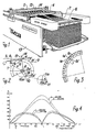
- Fig. 1 shows a perspective view of a stencil printing machine having a curved printing table in accordance with the present invention in which the printing table is so arranged as to rotate about a rotating shaft.
- the printing table 1 and its point of attachment which is capable of rotating about a rotating shaft 2 are illustrated in detail in the drawing in Fig. 2 showing the basic principle.
- the printing table 1 may be imparted with a reciprocating rotary motion by the to-and-fro motion of a drive organ 3 .
- a stencil 5 fixed in a frame 4 is so arranged as to follow the motion of the printing table 1 and is thereby displaced in relation to the scraper and ink charging devices, which are in a stationary relationship to a frame forming part of the stencil printing machine.
- the frame has been given the reference designation 13 whilst the scraper device has been given the reference designation 14 and the ink charging device the reference designation 15 .
- the material to be printed 6 is capable of being fed between the stencil 5 and the printing table 1 .
- the printing table has.a printing surface occupying rather less than half and preferably less than 170° of the surface of a complete cylinder.
- the example of the preferred embodiment shows the cylindrical surface to occupy no more than 120° of a complete cylinder. It should be pointed out in this connection that the cylindrical surface should not occupy less than 45° of the surface of the complete cylinder.
- the present invention proposes that the radius of curvature should be selected within the range 400 - 500 mm .
- the radius of curvature has been given the reference designation R in Fig. 2.
- the printing surface 1a of the printing table 1 is in the form of an outer sleeve beneath which are arranged preferably hollow strengthening elements 1b .
- the strengthening element may best consist of a low-pressure chamber.
- the outer sleeve consists of an 0.8 mm steel sheet attached to a perforated strengthening element with a thickness of between 25 and 50 mm. Two end-plates made of aluminium are attached to the printing table.
- Fig. 3 shows the printing surface of the printing table to consist partly of said outer sleeve 1a together with a number of adjacent segments incorporating low-pressure chambers, each low-pressure chamber being. capable of being connected to a source of low pressure, with small holes 1a' being arranged between the cavity 1b of the hollow profile and the printing surface 1a enabling the material to be held in position against the printing surface if this should be considered necessary.
- the cavities of the low-pressure chambers are connected to a valve (not shown in the Figures) which may be controlled so as to connect the low pressure only to a certain number of the cavities of the hollow profile, although it is also possible to cause the valve to connect all the low-pressure chambers to the source of low pressure immediately before the gripping organ 8 releases its hold on the material.
- the motion of the printing table 1 is controlled by a rod 10 , of which one end 10a is attached to the printing table in such a way that it is free to rotate and of which the other end 10b is attached to a shaft 11 rotating in a circular path in such a way that it is free to rotate.
- the speed of rotation may be varied by a previously disclosed method, and may be set for even speed and/or acceleration for a single revolution or for variable speed and/or acceleration for a single revolution.
- the points of attachment 10a and 10b of the rod 10 are positioned in such a way that the speed of movement of the printing table during the printing phase resembles..a curve with an initial increase in speed (not printing), a constant or essentially constant speed (printing) and a final reduction in speed (not printing), whilst the speed of the reciprocating motion of the printing table 1 is characterized by its initial high speed and its final low speed. This is illustrated best in Fig. 4. Particular attention should.be paid to the fact that, during the final low-speed phase, registration of the material and the engagement of the material in any gripping organs may take place, which is a contributory factor to the ability of the stencil printing machine to print at a considerable speed.
- One further advantage of a stencil printing machine in accordance with the present invention is that the space below the rotating shaft 2 may be used to accommodate other component parts of the stencil printing machine.
- the variation in the speed of the printing table referred to above is dependent partly on the position of the rotating shaft 11a in relation to the rotating shaft 2 , and partly on the distance between the centre-line 2a of the rotating shaft 2 and the point of attachment 10a l of the rod. This distance may differ to a certain extent from the distance between the rotating shaft 11a and the rotating shaft 11 .
- One other factor which is significant to the regulation of the speed of the printing table is whether the rotating shaft 11a is in a higher or lower position.
- a bold line is used in Fig. 4 to indicate the speed of the printing table, and the actual printing should be arranged to.take place between the angular values "35" and "145" , when the speed is essentially constant. It is also possible with the help of control devices to vary the speed of the shaft 11 immediately prior to this period, thereby achieving a more constant speed during the printing phase than that illustrated in the Figure.
- the embodiment of the present invention exhibits a curved printing table in which the cylindrical surface occupies rather less than 120° of the surface of a complete cylinder.
- the printing table 1 is so arranged as to rotate in order to produce a reciprocating motion about a rotating shaft 2 .
- the printing table is driven by a drive organ 3 , which itself is so arranged as to produce the reciprocating motion of a rod 10 .
- a stencil 5 fixed in a frame operates in conjunction with the motion of the printing table via connecting organs not shown in the Figure,for example a rack and pinion, and -is thereby imparted with displacement in relation to the scraper and ink charging devices which are in a stationary relationship.
- the material to be printed may best be transported by a material feed conveyor 7 to the printing table so that it may be brought into contact with gripping organs 8 incorporated in the printing table.
- gripping organs take hold of the leading edge of the material, and the motion of the printing table causes the material to pass over the contact point or contact line of the scraper with the stencil and the printing table, whereupon the gripping organs 8 release their hold on the-material in order to feed a sheet of material which has been printed to a material delivery conveyor 9.
- angular values indicated in Fig. 4 relate to the rotation of the shaft 11 about its centre of rotation 11a.
- the thin line shown in Fig. 4 indicates the speed curve for a rather larger format.
Landscapes
- Engineering & Computer Science (AREA)
- Mechanical Engineering (AREA)
- Printing Methods (AREA)
Priority Applications (1)
| Application Number | Priority Date | Filing Date | Title |
|---|---|---|---|
| EP81850169A EP0075640A1 (de) | 1981-09-28 | 1981-09-28 | Siebdruckmaschine mit zylindrischer Gegendruckplatte |
Applications Claiming Priority (1)
| Application Number | Priority Date | Filing Date | Title |
|---|---|---|---|
| EP81850169A EP0075640A1 (de) | 1981-09-28 | 1981-09-28 | Siebdruckmaschine mit zylindrischer Gegendruckplatte |
Publications (1)
| Publication Number | Publication Date |
|---|---|
| EP0075640A1 true EP0075640A1 (de) | 1983-04-06 |
Family
ID=8188740
Family Applications (1)
| Application Number | Title | Priority Date | Filing Date |
|---|---|---|---|
| EP81850169A Withdrawn EP0075640A1 (de) | 1981-09-28 | 1981-09-28 | Siebdruckmaschine mit zylindrischer Gegendruckplatte |
Country Status (1)
| Country | Link |
|---|---|
| EP (1) | EP0075640A1 (de) |
Citations (5)
| Publication number | Priority date | Publication date | Assignee | Title |
|---|---|---|---|---|
| US1742249A (en) * | 1928-03-28 | 1930-01-07 | Russell G Reilly | Stenciling machine |
| US2606492A (en) * | 1948-06-12 | 1952-08-12 | James A Black | Silk screen stenciling machine |
| US2950673A (en) * | 1957-12-02 | 1960-08-30 | Mccormick William Philip | Printing machines |
| US3229627A (en) * | 1963-08-19 | 1966-01-18 | Erwin P Pollitt | Multicolor screen printing press |
| DE2016377A1 (de) * | 1970-04-06 | 1971-10-28 | Schnellpressenfabrik Frankenthal Albert & Cie, AG, 6710 Frankenthal | Siebdruckmaschine |
-
1981
- 1981-09-28 EP EP81850169A patent/EP0075640A1/de not_active Withdrawn
Patent Citations (5)
| Publication number | Priority date | Publication date | Assignee | Title |
|---|---|---|---|---|
| US1742249A (en) * | 1928-03-28 | 1930-01-07 | Russell G Reilly | Stenciling machine |
| US2606492A (en) * | 1948-06-12 | 1952-08-12 | James A Black | Silk screen stenciling machine |
| US2950673A (en) * | 1957-12-02 | 1960-08-30 | Mccormick William Philip | Printing machines |
| US3229627A (en) * | 1963-08-19 | 1966-01-18 | Erwin P Pollitt | Multicolor screen printing press |
| DE2016377A1 (de) * | 1970-04-06 | 1971-10-28 | Schnellpressenfabrik Frankenthal Albert & Cie, AG, 6710 Frankenthal | Siebdruckmaschine |
Similar Documents
| Publication | Publication Date | Title |
|---|---|---|
| EP0581019B1 (de) | Gummituch einer Offsetdruckmaschine | |
| EP0895857B1 (de) | Vorrichtung und Verfahren zum Wechseln des Druckbildes während des Betriebs einer Druckmaschine | |
| WO2018015134A1 (de) | Vorrichtung und verfahren zum bedrucken von hohlkörpern mit linear verstellbarer zuführeinrichtung | |
| EP0513756A1 (de) | Druckeinstellungsvorrichtung für Druckzylinder | |
| EP1531043B1 (de) | Verfahren und Vorrichtung zum Verschieben eines Rakelmessers | |
| EP0075640A1 (de) | Siebdruckmaschine mit zylindrischer Gegendruckplatte | |
| DE19732059C2 (de) | Farbwerk für eine Rotationsdruckmaschine | |
| DE10259495B4 (de) | Farbwerk einer Druckmaschine | |
| EP0475120A1 (de) | Hochgeschwindigkeitsfarbzufuhrmechanismus | |
| US4487124A (en) | Shock and oscillation reducing apparatus for printing machine cylinders | |
| EP1362696A1 (de) | Druckmaschine mit Rakelvorrichtung | |
| US5265527A (en) | Offset printing press with emulsification control | |
| US4753167A (en) | Vibrator roll assembly for ink supply and transfer apparatus | |
| DE4438757C2 (de) | Vorgreifer für Bogenrotationsdruckmaschinen | |
| DE4109824C2 (de) | Kurvengesteuertes Leistungsausgleichsgetriebe | |
| JPS5889367A (ja) | 曲面型印刷テ−ブルを備えたステンシル印刷機 | |
| DE3153173C2 (de) | Druckwalzenmechanismus für ein Druckwerk | |
| GB2037663A (en) | Messenger roller drive apparatus | |
| EP0320226A2 (de) | Vorwischrakel | |
| DE19532856A1 (de) | Bogendruckmaschine mit Zuführvorrichtung | |
| EP0467124B1 (de) | Schnell hin- und herbwegliche Hebwalze | |
| DE633481C (de) | Bogenanlegevorrichtung | |
| DE102018121540A1 (de) | Vorrichtung zum Bedrucken von Hohlkörpern | |
| DE2834045C3 (de) | Bogenübergabevorrichtung zur paßgenauen Übergabe eines Druckbogens | |
| JPS6381045A (ja) | 印刷機のインキ装置 |
Legal Events
| Date | Code | Title | Description |
|---|---|---|---|
| PUAI | Public reference made under article 153(3) epc to a published international application that has entered the european phase |
Free format text: ORIGINAL CODE: 0009012 |
|
| AK | Designated contracting states |
Designated state(s): DE FR GB IT |
|
| STAA | Information on the status of an ep patent application or granted ep patent |
Free format text: STATUS: THE APPLICATION HAS BEEN WITHDRAWN |
|
| 18W | Application withdrawn |
Withdrawal date: 19840320 |
|
| RIN1 | Information on inventor provided before grant (corrected) |
Inventor name: SCHERP, SVEN |