EP0075096B1 - Zahnärztliches Handinstrument mit Beleuchtungsvorrichtung - Google Patents
Zahnärztliches Handinstrument mit Beleuchtungsvorrichtung Download PDFInfo
- Publication number
- EP0075096B1 EP0075096B1 EP82107202A EP82107202A EP0075096B1 EP 0075096 B1 EP0075096 B1 EP 0075096B1 EP 82107202 A EP82107202 A EP 82107202A EP 82107202 A EP82107202 A EP 82107202A EP 0075096 B1 EP0075096 B1 EP 0075096B1
- Authority
- EP
- European Patent Office
- Prior art keywords
- light
- handpiece
- arrangement
- conducting
- handpiece arrangement
- Prior art date
- Legal status (The legal status is an assumption and is not a legal conclusion. Google has not performed a legal analysis and makes no representation as to the accuracy of the status listed.)
- Expired
Links
- 230000005540 biological transmission Effects 0.000 claims abstract description 62
- 230000003287 optical effect Effects 0.000 claims abstract description 6
- 239000004020 conductor Substances 0.000 claims description 18
- 230000007704 transition Effects 0.000 claims description 7
- 239000000835 fiber Substances 0.000 claims description 6
- 239000007921 spray Substances 0.000 claims description 6
- 239000011521 glass Substances 0.000 claims description 5
- 239000002826 coolant Substances 0.000 claims description 4
- 239000012141 concentrate Substances 0.000 claims description 2
- 239000000945 filler Substances 0.000 claims description 2
- 239000005304 optical glass Substances 0.000 claims description 2
- XLYOFNOQVPJJNP-UHFFFAOYSA-N water Substances O XLYOFNOQVPJJNP-UHFFFAOYSA-N 0.000 claims description 2
- 241001212149 Cathetus Species 0.000 claims 1
- VVQNEPGJFQJSBK-UHFFFAOYSA-N Methyl methacrylate Chemical compound COC(=O)C(C)=C VVQNEPGJFQJSBK-UHFFFAOYSA-N 0.000 claims 1
- 229920005372 Plexiglas® Polymers 0.000 claims 1
- 230000006978 adaptation Effects 0.000 claims 1
- 239000012876 carrier material Substances 0.000 claims 1
- 230000002093 peripheral effect Effects 0.000 claims 1
- 230000008878 coupling Effects 0.000 abstract description 5
- 238000010168 coupling process Methods 0.000 abstract description 5
- 238000005859 coupling reaction Methods 0.000 abstract description 5
- 239000013307 optical fiber Substances 0.000 description 13
- 239000003365 glass fiber Substances 0.000 description 4
- 238000000926 separation method Methods 0.000 description 3
- 238000011161 development Methods 0.000 description 2
- 230000018109 developmental process Effects 0.000 description 2
- 238000002360 preparation method Methods 0.000 description 2
- 238000005266 casting Methods 0.000 description 1
- 238000010276 construction Methods 0.000 description 1
- 230000001419 dependent effect Effects 0.000 description 1
- 238000010586 diagram Methods 0.000 description 1
- 239000012530 fluid Substances 0.000 description 1
- 238000005286 illumination Methods 0.000 description 1
- 239000000463 material Substances 0.000 description 1
- 230000005855 radiation Effects 0.000 description 1
- 239000011347 resin Substances 0.000 description 1
- 229920005989 resin Polymers 0.000 description 1
Images


Classifications
-
- A—HUMAN NECESSITIES
- A61—MEDICAL OR VETERINARY SCIENCE; HYGIENE
- A61C—DENTISTRY; APPARATUS OR METHODS FOR ORAL OR DENTAL HYGIENE
- A61C1/00—Dental machines for boring or cutting ; General features of dental machines or apparatus, e.g. hand-piece design
- A61C1/08—Machine parts specially adapted for dentistry
- A61C1/088—Illuminating devices or attachments
Definitions
- the invention relates to a dental handpiece arrangement with two handpiece parts which are rotatable relative to one another about their longitudinal axes and preferably axially separable from one another and which guide members ensure the rotatability of the parts, e.g. a guide pin in one and a matching guide sleeve in the other handpiece part, with a locking device for axially fixing the two handpiece parts in the coupled state, and with a light guide leading to the head part of the handpiece arrangement.
- guide members ensure the rotatability of the parts, e.g. a guide pin in one and a matching guide sleeve in the other handpiece part, with a locking device for axially fixing the two handpiece parts in the coupled state, and with a light guide leading to the head part of the handpiece arrangement.
- the invention specified in claim 1 has for its object to provide a handpiece arrangement of the type mentioned, with which it is possible while avoiding annoying cables, light for illumination z.
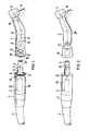
- FIG. 1 and 2 show a diagrammatic, greatly simplified representation of various embodiments of a light guide or transmission from the drive part to the handle part of a dental handpiece arrangement.
- FIG. 1 shows a dental drive part 1 with a schematically drawn electric motor 2, to which electrical energy is supplied in a known manner via a supply hose 3.
- the drive shaft 4 (shown schematically) of the motor 2 is surrounded by a guide pin 5 which fits into a matching guide sleeve 6 of a handle part 7 when the two parts are axially coupled to one another.
- the drive shaft 4 is coupled to drive shaft sections 8 which drive a tool 10 which is rotatably mounted in the head housing 9 of the handle part 7.
- a known locking lug is designated, which is mounted radially resiliently in the guide pin 5 and comes into engagement with a corresponding annular groove 12 when coupling the handle part 7. This on the one hand prevents unwanted axial sliding of the handle part 7 from the drive part 1, and on the other hand ensures the rotatability of the two parts about their longitudinal axes.
- the latching device is expediently designed such that the handle part is operational, i.e. can easily be separated from the drive part 1 without the aid of a tool.
- a further light transmission ring 20 is also arranged with an end face 18 of the grip part 7, which correspondingly faces the light transmission ring 14 when the two handpiece parts 1 and 7 are coupled.
- the light transmission ring 20 is connected to a further light guide 21, the end of which contains the light exit point and is directed towards the tool 10 is fastened to the handle part 7 by means of a clamp 19.
- light is transmitted through two light transmission rings arranged coaxially to the guide pin 5 ge, which are arranged on the end faces of the motor housing 22 of the drive part and on the other hand of the handle part 7 and face each other correspondingly in the coupled state.
- an arrangement of the light transmission ring on the end face of the guide pin 5, designated by position 23, is also conceivable; Accordingly, the matching light transmission ring in the handle part 7 would have to be provided at the point designated by 24, that is to say at the end of the guide sleeve 6.
- FIG. 2 shows an embodiment in which a light transmission ring 25 is provided on the circumference of the guide pin 5 and has a radial light emission surface.
- the light transmission ring 25 is fed by a light guide 26, which in turn is fed either by a lamp arranged internally or externally of the drive part.
- a light transmission ring 27 is arranged in the grip part 7 in the coupled state of the drive part 1 and grip part 7, concentrically to the light transmission ring 25, on which a light guide 28 leading to the head housing 9 is optically, ie. H. in the sense of a light transmission, is coupled.
- the drive part 1 is expediently provided with an attachment in which a light transmission ring is arranged, which in the coupled state of the two handpiece parts is overlapped by a further light transmission ring in the transition piece 17 of the grip part 7, which is not shown in the illustration.
- the arrangement of the light transmission ring in the conically shaped transition piece 17 is advantageous insofar as this conical part is already present in the handpiece arrangements of this type in order to get a smooth transition from the larger drive part 1 to the smaller handle part 7; therefore no additional space is required.
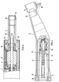
- FIG. 3 and 4 show details of the solution shown in FIG. 1, the illustration of the mechanical coupling means 11, 12 known per se being omitted for the sake of clarity.
- FIG 3 shows a longitudinal section of the drive part 1 in the embodiment with the incandescent lamp 15 as a light source for feeding the light transmission ring 14.
- the incandescent lamp 15 as a light source for feeding the light transmission ring 14.
- the light transmission ring 14 is arranged in a flange 29 of the guide pin 5. In the arrangement, light entry and exit thus take place at the end.
- the electrical lines of the lamp 15 are laid in a hollow channel of the stator, not shown in detail.
- FIG. 4 shows the handle part 7, shown diagrammatically in FIG. 1, partly in longitudinal section.
- the light transmission ring 20, to which the light guide 21 leading to the head housing 9 is connected, is inserted here in a recess of the conical transition piece 17.
- the light transfer from the drive part 1 to the handle part 7 can also be punctiform, e.g. in that the light bulb 15 illuminates the light transmission ring 20 in the grip part 7 directly, with the omission of the light transmission ring 14, or by the end of a light guide with a circular cross section opening at the end of the drive part.
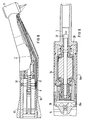
- FIG. 5 shows an embodiment in which the incandescent lamp 15 is arranged in a connection part 34 of the drive part.
- two end pieces 36, 36a are merged, each with mirrored surfaces that are bevelled at 45 °, which take the light from the incandescent lamp 15 and transfer it into light-guiding bodies 37, 37a, which in turn are optically coupled to a rotationally symmetrical sleeve-shaped part 38.
- the part 38 has at the end of the guide pin 5 an annular surface 39, on which the light emerges radially.
- the two light guide bodies 37, 37a are arranged between two magnetic shells 40, 40a of the stator of the electric motor.
- the intermediate channels 41, 41a serve in a manner known per se to supply a fluid coolant (water or spray). As is known, the course of these channels is not to be shown and explained further here.
- FIG. 7 shows the light guide in the handle part 7 that matches the drive part 1 according to FIG. 5.
- the annular surface 39 of the light guide body 38 stands on the guide pin 5 of the ring-shaped one Surface of the light transmission ring 42 correspondingly opposite, whereby there is a radial light transfer or takeover.
- the light is transmitted from the light transmission ring 42 to the head part 9 via a light guide 43 which is round in cross section and which opens into a cover 44 which is arranged on the end of the head housing 9 facing the tool 10 and forms the outer end of a spray channel denoted by 45 .
- the lid 44 is made of light-conducting material and contains for the exit of the cooling medium from the Spray channel 45 one or more outlet openings 46.
- this light guide itself or parts of it can also be used for guiding the light. It is conceivable z. B. to transfer the light from the light transmission ring 42 to the then made of light-conducting material parts 47, 48 and 49.
- FIG. 8 shows an embodiment in which the light is transferred from a light transmission ring 50 into a glass tube 51, which serves for cooling medium inside, which is supplied in a known manner from the drive part via an annular channel 52 and an axially parallel medium line 53, to head to the headboard 9.
- FIG. 9 shows an embodiment in which, in contrast to that according to FIG. 5, the light thrown by the incandescent lamp 15 onto the two end pieces 36, 36a is passed on by two half-shells 54, 54a which surround the outer jacket of the drive motor and As shown in Fig. 3, end face in the flange 29 of the guide pin 5.
- the light can then, as shown in FIGS. 3 and 4, be transmitted axially parallel or, as already indicated in the description of FIG. 2, by radially reaching over the half-shells 54, 54a by means of a sleeve-like end piece of the handle part.
- FIG. 10 shows the complete light transmission body in a diagrammatic representation.
- two mutually corresponding light transmission rings are always provided in the exemplary embodiments described, it is conceivable and within the scope of the invention to arrange only one light transmission ring on one handpiece part, advantageously on the handpiece part which transmits the light, and on the other handpiece part corresponding to the light transmission ring or to provide a plurality of light sources arranged on the circumference.
- Such light sources can be both lamps and externally fed light guides that end directly on the end faces of the handpiece part in question.
- FIGS. 11 to 16 are in principle also suitable for radially transferring the light if the corresponding light guide ends with the light exit or entry surfaces are located radially on the circumference of the relevant handpiece part, as is the case, for example, in FIG. 5 and 7 are arranged.
- FIG. 11 shows an embodiment of a light transmission ring which is suitable for transmitting the light in the axial direction from one handpiece part to the other.
- a light transmission ring can be provided, for example, for positions 14, 20, 30 and 31 of FIGS. 3, 4.
- the light transmission ring is formed here by a carrier part 55, which has an annular recess 56 in which individual optical fibers 57, ... n of an optical fiber bundle 58 are laid, in such a way that the optical fiber ends 57a are evenly arranged on a circle with the diameter d Are arranged circumferentially distributed.
- recesses corresponding to the diameter of the individual optical fibers for example bores 59, are provided in the carrier part 55, through which the optical fibers are drawn.
- the cavity 60 existing after the light fibers have been laid is poured out by a suitable filler material, for example a casting resin, as a result of which the individual optical fibers are fixed in the carrier part 55.
- a suitable filler material for example a casting resin
- the support part 55 is ground on the end face after the light guide has been installed.
- the proposed arrangement enables light to flow from a light guide with a circular cross section and thus point radiation on a diameter that is, in contrast, much larger and vice versa.
- a plurality of such circularly arranged optical fibers can be arranged concentrically one above the other in the carrier part 55.
- optical fiber ends end not on the end face of a circular ring but on the circumferential surface of a ring, as a result of which a radial light transmission similar to positions 25/27 in FIG. 2 or 39/42 in FIG. 5 / 7 is possible.
- FIG. 12 to 14 show another embodiment of a light transmission ring.
- a plurality of individual light guides 62 are arranged on an annular support part 61 distributed around the circumference, in such a way that their ends 63 terminate on the end face with the ring surface 64 of the support part 61 and completely fill this circular cross-section and that their other ends 65 (FIG. 13 ) are optically coupled to a surface 66 of a collecting prism 67 (FIG. 14).
- the individual light guides 62 are approximately wedge-shaped while maintaining the cross-sectional areas 63, 65.
- a light guide 68 with a circular cross section then connects to the collecting prism 67.
- the collecting prism 67 and the individual light guides 62 are advantageously made of optical glass, but can also be formed from individual light guide fibers.
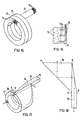
- 15 and 16 show another embodiment of a light transmission ring.
- the individual optical fibers 70 of an optical fiber bundle 71 are uniformly contained in an annular carrier 72.
- a ring 73 with a multiplicity of optical lenses 74 is placed on the face of the carrier 72, which form the light transmission surface and concentrate the incident light into the optical fiber ends 70a arranged in the focal point of the light guide 70 (FIG. 16)
- the previously described exemplary embodiment the sum of the light guides 70 arranged on the circumference in the carrier part 72 and the number of optical fibers contained in the fiber bundle 71.
- the converging lenses 74 are advantageously arranged such that the first one distance between the individual optical fiber ends 70a are fully filled.
- Fig. 17 shows an embodiment of a light transmission ring, which is particularly suitable for a point feed of the light.
- a light transmission ring is therefore to be provided if only one handpiece part has a light transmission ring, the other handpiece part against it, for. B. for space reasons, only a selective transmission of light with full rotation of the two handpiece parts allowed.
- the light transmission ring here consists of a deflection prism 76, which has an annular light entry surface 77 and is optically coupled to a collecting prism 78, to the free end 79 of which a light guide can be connected. 18 shows the development of the deflection prism 76.
- the slope B, D of the collecting prism 78 is selected such that the light is transmitted approximately in the direction of the light guide coupled to the end 79.
- the other surfaces of the two glass bodies 76, 78 are also mirrored on the outside.
- the embodiment described is particularly suitable for punctiform incidence of light on the end face 77 of the glass body 76 (see arrow in FIG. 17); it can of course also be used for an annular light coupling.
- the embodiments shown in FIGS. 19 to 22 can only be used if a light transmitter can be provided on both handpiece parts.
- the light transmitter in both handpiece parts 1 and 7 here consists of an annular channel 80, each with a half 80a or 80b, which is assigned to one (1) or the other handpiece part (7).
- the entire ring channel 80 is mirrored on the inside or highly polished, as a result of which the light fed in via the light guide 81 is reflected on the walls (see arrow illustration).
- the end piece 82 forms a deflection prism; its surface 84, which is bevelled at 45 °, is also optically mirrored, so that the light coming from the ring channel 80 is deflected axially parallel in accordance with the arrow representation.
- the light guide 83 is arranged outside the longitudinal axis of symmetry of the handpiece parts, the two handpiece parts can be rotated through 360 °.
- FIG. 21 shows a similar solution, but with axially parallel feeding of the light.
- the end 85 of the light guide 86 like the end 87 of the light guide 88, is designed as a deflection prism.
- the two surfaces 89, 90 running at 45 ° are optically isolated from one another so that no light refraction can occur at the two ends of the light guide.
- the 22 shows the two light guide ends 85, 87 in a perspective view.
- the light guide ends are arranged outside the longitudinal axis of symmetry of the handpiece parts, as a result of which there is light transmission in every rotational position of the handpiece parts.
- the coupling point is always the pivot point of the two handpiece parts, this is not absolutely necessary.
- the pivot and separation point can therefore also be arranged separately from one another at different points on the handpiece parts.
- the light transmitter (s) are then to be arranged at the turning point; a light transmission at the point of separation, after no rotation here, z. B. by butting light guide ends.
Landscapes
- Health & Medical Sciences (AREA)
- Oral & Maxillofacial Surgery (AREA)
- Dentistry (AREA)
- Epidemiology (AREA)
- Life Sciences & Earth Sciences (AREA)
- Animal Behavior & Ethology (AREA)
- General Health & Medical Sciences (AREA)
- Public Health (AREA)
- Veterinary Medicine (AREA)
- Dental Tools And Instruments Or Auxiliary Dental Instruments (AREA)
Priority Applications (1)
| Application Number | Priority Date | Filing Date | Title |
|---|---|---|---|
| AT82107202T ATE20174T1 (de) | 1981-08-20 | 1982-08-09 | Zahnaerztliches handinstrument mit beleuchtungsvorrichtung. |
Applications Claiming Priority (2)
| Application Number | Priority Date | Filing Date | Title |
|---|---|---|---|
| DE3132995 | 1981-08-20 | ||
| DE19813132995 DE3132995A1 (de) | 1981-08-20 | 1981-08-20 | Zahnaerztliche handstueckanordnung |
Publications (2)
| Publication Number | Publication Date |
|---|---|
| EP0075096A1 EP0075096A1 (de) | 1983-03-30 |
| EP0075096B1 true EP0075096B1 (de) | 1986-06-04 |
Family
ID=6139756
Family Applications (1)
| Application Number | Title | Priority Date | Filing Date |
|---|---|---|---|
| EP82107202A Expired EP0075096B1 (de) | 1981-08-20 | 1982-08-09 | Zahnärztliches Handinstrument mit Beleuchtungsvorrichtung |
Country Status (5)
| Country | Link |
|---|---|
| US (1) | US4460337A (enExample) |
| EP (1) | EP0075096B1 (enExample) |
| JP (1) | JPS5841544A (enExample) |
| AT (1) | ATE20174T1 (enExample) |
| DE (2) | DE3132995A1 (enExample) |
Families Citing this family (42)
| Publication number | Priority date | Publication date | Assignee | Title |
|---|---|---|---|---|
| DE3215210A1 (de) * | 1982-04-23 | 1983-10-27 | Kaltenbach & Voigt Gmbh & Co, 7950 Biberach | Zahnaerztliches handstueck |
| DE3215193A1 (de) * | 1982-04-23 | 1983-10-27 | Kaltenbach & Voigt Gmbh & Co, 7950 Biberach | Zahnaerztliches handstueck |
| DE3215219A1 (de) * | 1982-04-23 | 1983-10-27 | Kaltenbach & Voigt Gmbh & Co, 7950 Biberach | Zahnaerztliches handstueck |
| JPS59133206U (ja) * | 1983-02-26 | 1984-09-06 | 長田電機工業株式会社 | 照明灯付モ−タハンドピ−ス |
| JPS59169811U (ja) * | 1983-04-28 | 1984-11-13 | 株式会社 モリタ製作所 | 歯科用エア−駆動型ハンドピ−ス |
| JPS59218147A (ja) * | 1983-05-24 | 1984-12-08 | 株式会社吉田製作所 | 歯科治療器具の照明機構 |
| DE3328604A1 (de) * | 1983-08-08 | 1985-02-28 | Kaltenbach & Voigt Gmbh & Co, 7950 Biberach | Zahnsteinentfernungs-handstueck |
| DE3332628A1 (de) * | 1983-09-09 | 1985-04-04 | Kaltenbach & Voigt Gmbh & Co, 7950 Biberach | Zahnaerztliches handstueck |
| DE3332627A1 (de) * | 1983-09-09 | 1985-04-04 | Kaltenbach & Voigt Gmbh & Co, 7950 Biberach | Zahnaerztliches handstueck |
| DE3339650A1 (de) * | 1983-11-02 | 1985-05-09 | Siemens AG, 1000 Berlin und 8000 München | Kupplungsvorrichtung zum axialen verbinden von zwei teilen einer zahnaerztlichen handstueckanordnung |
| DE3339669A1 (de) * | 1983-11-02 | 1985-05-09 | Siemens AG, 1000 Berlin und 8000 München | Zahnaerztliche handstueckanordnung mit mitteln zur lichtuebertragung |
| JPS60138512U (ja) * | 1984-02-24 | 1985-09-13 | 株式会社 吉田製作所 | 歯科用治療器具 |
| US4600384A (en) * | 1984-09-28 | 1986-07-15 | Sybron Corporation | Swivel coupling for illuminated dental handpiece |
| CH665767A5 (fr) * | 1984-11-07 | 1988-06-15 | Micro Mega Sa | Contre-angle pour piece a main dentaire. |
| US4681540A (en) * | 1984-11-09 | 1987-07-21 | Siemens Aktiengesellschaft | Dental handpiece arrangement |
| DE3570588D1 (en) * | 1984-12-21 | 1989-07-06 | Siemens Ag | Dental hand piece with a lighting device |
| DE8510667U1 (de) * | 1985-04-11 | 1986-08-07 | Hüttenmoser, Hans, Kronbühl | Zahnärztliche Handstückanordnung |
| EP0255661A1 (de) * | 1986-08-04 | 1988-02-10 | Siemens Aktiengesellschaft | Zahnärztliches Handstück mit integriertem Lichtleiter |
| DE3706943A1 (de) * | 1987-03-04 | 1988-09-22 | Medtronic Medizinisch Elektron | Beleuchtungseinrichtung fuer ein zahnaerztliches handinstrument |
| JPH02198544A (ja) * | 1988-11-21 | 1990-08-07 | Dentalwerk Buermoos Gmbh | 歯科用アングル・ハンドピースのための結合部 |
| DE3910474A1 (de) * | 1989-03-31 | 1990-10-04 | Kaltenbach & Voigt | Aerztliches oder zahnaerztliches handstueck mit einem langgestreckten lichtleiter in form eines glas- oder glasfaserstabes |
| US5147204A (en) * | 1991-08-08 | 1992-09-15 | Minnesota Mining And Manufacturing Co. | Dental material curing apparatus |
| USD336337S (en) | 1991-08-08 | 1993-06-08 | Minnesota Mining And Manufacturing Company | Dental material curing apparatus |
| DE19511262C1 (de) * | 1995-03-27 | 1996-08-22 | Siemens Ag | Zahnärztliches Behandlungsinstrument mit Beleuchtungseinrichtung |
| US6208788B1 (en) * | 1998-07-29 | 2001-03-27 | Ultradent Products, Inc. | Apparatus and methods for concentrating light through fiber optic funnels coupled to dental light guides |
| US20020168612A1 (en) * | 2000-09-14 | 2002-11-14 | Novak Eugene J. | Bearing for dental handpiece |
| US20060234186A1 (en) * | 2000-09-14 | 2006-10-19 | Novak Eugene J | Bearing for dental handpiece |
| US20070059664A1 (en) * | 2000-09-14 | 2007-03-15 | Novak Eugene J | Bearing for dental handpiece |
| EP1355580A1 (en) * | 2000-12-18 | 2003-10-29 | Dentsply International, Inc. | Improved dental handpiece components |
| US20020124443A1 (en) * | 2000-12-18 | 2002-09-12 | Dentsply Research & Development Corp. | Metal-to-metal connections |
| US20070031786A1 (en) * | 2002-02-25 | 2007-02-08 | Heil Donald J | Dental handpiece |
| US20030170589A1 (en) * | 2002-02-27 | 2003-09-11 | Novak Eugene J. | Dental handpiece with improved grease retention |
| US20070117064A1 (en) * | 2002-02-27 | 2007-05-24 | Novak Eugene J | Dental handpiece with improved grease retention |
| WO2003083266A1 (en) * | 2002-03-28 | 2003-10-09 | Dentsply International Inc. | Method for balancing the rotating turbine element of a dental handpiece |
| US20060191336A1 (en) * | 2002-03-28 | 2006-08-31 | Dentsply Research & Development Corp. | Method and apparatus for balancing the rotating elements of a dental handpiece |
| DE10248924A1 (de) * | 2002-10-17 | 2004-04-29 | C. & E. Fein Gmbh & Co Kg | Elektrowerkzeug |
| EP1845884B1 (en) * | 2005-02-07 | 2009-08-12 | Amdent AB | Dental handpiece |
| DE102005044889A1 (de) * | 2005-09-20 | 2007-03-29 | Siemens Ag | Zahnmedizinisches Untersuchungs- und/oder Behandlungswerkezug |
| US20100035205A1 (en) * | 2008-08-09 | 2010-02-11 | Daniel Wang | Non-90-Degree Ergonomically-Shaped Dental Prophylaxis Angle with a Straight Driving Shaft |
| DE102010028245A1 (de) * | 2010-04-27 | 2011-10-27 | Kaltenbach & Voigt Gmbh | Elektromotoranordnung für ein medizinisches, insbesondere ein dentales Handstück, sowie Dentalinstrumententeil |
| KR101157524B1 (ko) * | 2011-03-15 | 2012-06-22 | 두나미스덴탈 주식회사 | 라이트 가이드를 포함하는 치과용 핸드피스 |
| US12429213B2 (en) | 2023-05-16 | 2025-09-30 | Milwaukee Electric Tool Corporation | Power tool utilizing optical fibers to output light |
Family Cites Families (6)
| Publication number | Priority date | Publication date | Assignee | Title |
|---|---|---|---|---|
| US3109238A (en) * | 1961-11-28 | 1963-11-05 | Samuel B Marks | Portable dental drill |
| US3590232A (en) * | 1968-03-27 | 1971-06-29 | Radioptics Inc | Annular illuminator for dental tools or the like |
| GB1281054A (en) * | 1969-10-16 | 1972-07-12 | Vann Brothers Ltd | Improvements in or relating to dental handpieces |
| DE6940204U (de) * | 1969-10-16 | 1971-03-25 | Siemens Ag | Zahnaerztliches bohrhandstueck mit lichtleiter |
| US4020556A (en) * | 1972-01-14 | 1977-05-03 | Star Dental Manufacturing Co., Inc. | Air driven dental handpiece |
| DE2855719A1 (de) * | 1978-12-22 | 1980-07-10 | Siemens Ag | Zahnaerztliche handstueckanordnung |
-
1981
- 1981-08-20 DE DE19813132995 patent/DE3132995A1/de not_active Withdrawn
-
1982
- 1982-08-09 EP EP82107202A patent/EP0075096B1/de not_active Expired
- 1982-08-09 DE DE8282107202T patent/DE3271550D1/de not_active Expired
- 1982-08-09 AT AT82107202T patent/ATE20174T1/de not_active IP Right Cessation
- 1982-08-13 US US06/408,125 patent/US4460337A/en not_active Expired - Fee Related
- 1982-08-19 JP JP57143975A patent/JPS5841544A/ja active Granted
Also Published As
| Publication number | Publication date |
|---|---|
| EP0075096A1 (de) | 1983-03-30 |
| JPS611142B2 (enExample) | 1986-01-14 |
| ATE20174T1 (de) | 1986-06-15 |
| DE3132995A1 (de) | 1983-03-03 |
| US4460337A (en) | 1984-07-17 |
| DE3271550D1 (en) | 1986-07-10 |
| JPS5841544A (ja) | 1983-03-10 |
Similar Documents
| Publication | Publication Date | Title |
|---|---|---|
| EP0075096B1 (de) | Zahnärztliches Handinstrument mit Beleuchtungsvorrichtung | |
| DE3215207C2 (enExample) | ||
| EP0369043B2 (de) | Zahnärztliches Handstück mit Mitteln zum kompatiblen Anschluss an unterschiedlich gestaltete Drehkupplungen | |
| DE3215255C2 (de) | Zahnärztliche Handstückeinrichtung | |
| DE3104239C2 (de) | Zahnärztliches Handstück | |
| EP0185290B1 (de) | Zahnärztliche Handstückanordnung mit Beleuchtungseinrichtung | |
| DE2948564C2 (de) | Anschlußteil für ein Endoskop | |
| EP0183972B1 (de) | Zahnärztliche Handstückanordnung | |
| DE2159327C3 (de) | Vorrichtung zur Justierung zweier optischer Bauelemente | |
| DE3220540C2 (de) | Verbindungseinrichtung für Faserlichtleitungen | |
| DE3215210C2 (enExample) | ||
| DE2744108A1 (de) | Mehrkanalkoppler fuer lichtleitfaserverbindungen | |
| DE2842535A1 (de) | Abzweigelement | |
| DE3431052A1 (de) | Kupplungsvorrichtung fuer zahnaerztliche handstuecke | |
| DE2203357A1 (de) | Otoskop | |
| DE19613681C2 (de) | Dentales Handstück | |
| DE2913686B2 (de) | Steckkupplung für mehradrige hydraulische oder pneumatische Kabel | |
| DE3605389C2 (enExample) | ||
| EP0286790B1 (de) | Zahnärztliche Handstückanordnung mit Mitteln zur Lichtübertragung | |
| EP0085952B1 (de) | Mehradriges hydraulisches oder pneumatisches Kabel mit Mehrfachschlauchkupplung | |
| DE2934153A1 (de) | Verteilungskoppler | |
| DE2606062A1 (de) | Zahnaerztliches handstueck | |
| DE2708014C3 (de) | Stecker zur Ankopplung eines Einzellichtwellenleiters an einen anderen Einzellichtwellenleiter oder an einen Lichtsender oder Lichtempfänger | |
| DE3132996A1 (de) | Zahnaertzliche handstueckanordnung mit drehbar gelagertem triebwellenabschnitt | |
| DE3215193C2 (enExample) |
Legal Events
| Date | Code | Title | Description |
|---|---|---|---|
| PUAI | Public reference made under article 153(3) epc to a published international application that has entered the european phase |
Free format text: ORIGINAL CODE: 0009012 |
|
| AK | Designated contracting states |
Designated state(s): AT CH DE FR GB IT LI SE |
|
| 17P | Request for examination filed |
Effective date: 19830909 |
|
| GRAA | (expected) grant |
Free format text: ORIGINAL CODE: 0009210 |
|
| AK | Designated contracting states |
Kind code of ref document: B1 Designated state(s): AT CH DE FR GB IT LI SE |
|
| REF | Corresponds to: |
Ref document number: 20174 Country of ref document: AT Date of ref document: 19860615 Kind code of ref document: T |
|
| REF | Corresponds to: |
Ref document number: 3271550 Country of ref document: DE Date of ref document: 19860710 |
|
| ITF | It: translation for a ep patent filed | ||
| ET | Fr: translation filed | ||
| PGFP | Annual fee paid to national office [announced via postgrant information from national office to epo] |
Ref country code: AT Payment date: 19860805 Year of fee payment: 5 |
|
| PLBE | No opposition filed within time limit |
Free format text: ORIGINAL CODE: 0009261 |
|
| STAA | Information on the status of an ep patent application or granted ep patent |
Free format text: STATUS: NO OPPOSITION FILED WITHIN TIME LIMIT |
|
| 26N | No opposition filed | ||
| PG25 | Lapsed in a contracting state [announced via postgrant information from national office to epo] |
Ref country code: GB Free format text: LAPSE BECAUSE OF NON-PAYMENT OF DUE FEES Effective date: 19880809 Ref country code: AT Effective date: 19880809 |
|
| PG25 | Lapsed in a contracting state [announced via postgrant information from national office to epo] |
Ref country code: SE Effective date: 19880810 |
|
| PG25 | Lapsed in a contracting state [announced via postgrant information from national office to epo] |
Ref country code: LI Effective date: 19880831 Ref country code: CH Effective date: 19880831 |
|
| PG25 | Lapsed in a contracting state [announced via postgrant information from national office to epo] |
Ref country code: FR Free format text: LAPSE BECAUSE OF NON-PAYMENT OF DUE FEES Effective date: 19890428 |
|
| REG | Reference to a national code |
Ref country code: CH Ref legal event code: PL |
|
| GBPC | Gb: european patent ceased through non-payment of renewal fee | ||
| REG | Reference to a national code |
Ref country code: FR Ref legal event code: ST |
|
| PGFP | Annual fee paid to national office [announced via postgrant information from national office to epo] |
Ref country code: DE Payment date: 19931020 Year of fee payment: 12 |
|
| EUG | Se: european patent has lapsed |
Ref document number: 82107202.2 Effective date: 19890510 |
|
| PG25 | Lapsed in a contracting state [announced via postgrant information from national office to epo] |
Ref country code: DE Effective date: 19950503 |