EP0073940B1 - Dosierpumpe - Google Patents
Dosierpumpe Download PDFInfo
- Publication number
- EP0073940B1 EP0073940B1 EP82107147A EP82107147A EP0073940B1 EP 0073940 B1 EP0073940 B1 EP 0073940B1 EP 82107147 A EP82107147 A EP 82107147A EP 82107147 A EP82107147 A EP 82107147A EP 0073940 B1 EP0073940 B1 EP 0073940B1
- Authority
- EP
- European Patent Office
- Prior art keywords
- pump
- agent
- proportioned
- proportioning
- pump cylinder
- Prior art date
- Legal status (The legal status is an assumption and is not a legal conclusion. Google has not performed a legal analysis and makes no representation as to the accuracy of the status listed.)
- Expired
Links
Images
Classifications
-
- F—MECHANICAL ENGINEERING; LIGHTING; HEATING; WEAPONS; BLASTING
- F04—POSITIVE - DISPLACEMENT MACHINES FOR LIQUIDS; PUMPS FOR LIQUIDS OR ELASTIC FLUIDS
- F04B—POSITIVE-DISPLACEMENT MACHINES FOR LIQUIDS; PUMPS
- F04B23/00—Pumping installations or systems
- F04B23/04—Combinations of two or more pumps
- F04B23/06—Combinations of two or more pumps the pumps being all of reciprocating positive-displacement type
-
- F—MECHANICAL ENGINEERING; LIGHTING; HEATING; WEAPONS; BLASTING
- F04—POSITIVE - DISPLACEMENT MACHINES FOR LIQUIDS; PUMPS FOR LIQUIDS OR ELASTIC FLUIDS
- F04B—POSITIVE-DISPLACEMENT MACHINES FOR LIQUIDS; PUMPS
- F04B13/00—Pumps specially modified to deliver fixed or variable measured quantities
Definitions
- the invention relates to a metering pump according to the preamble of claim 1.
- Such a metering pump is known from FR-A-2 120 945.
- the pre-feed chamber is connected to a metering agent container via a suction valve and a suction line and via a pressure valve and a return line.
- the pre-delivery takes place via the suction line and the suction valve to the pre-delivery room.
- the dosing piston takes the required amount of dosing agent from the pre-delivery chamber.
- the excess amount of the dosing agent is conveyed back into the dosing agent container via the pressure valve and the return line. Due to the need to provide suction and pressure valves and a return line, the apparatus is relatively complex. Furthermore, the provision of suction and pressure lines between the pre-delivery chamber and the dosing agent container makes the bacteria and gas-tight connection between the dosing pump and the dosing agent container difficult.
- the object of the invention is to provide a metering pump of the type described in the introduction, in which, despite the high metering accuracy, the structure is simplified and the connection to the metering agent container is facilitated.
- the outlet of the pre-delivery chamber is preferably located at a higher level than the inlet of the pump cylinder. In this way, the dosing means always surrounds the pump piston, so that formation of deposits on the pump piston is avoided.
- the line section connecting the pre-delivery chamber to the dosing agent container is connected to a pump sump, which is connected to the pump cylinder via a line and a suction valve.
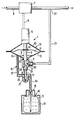
- the figure shows a schematic representation of a metering pump connected to a water supply with a metering agent container, partly in a sectional view.
- the metering pump 1 comprises a pump cylinder 2 with an inlet located at the top in the vertical direction and an outlet 3 near its lower end. Above the pump cylinder 2 there is a metering piston 4 which moves back and forth relative to the pump cylinder by means of a schematically illustrated lifting drive 5 and is thus immersed in or dipped out of it.
- the stroke drive 5 is connected by means of a control line 6 to a pulse generator 7, which delivers control pulses to the stroke drive as a function of the amount of liquid flowing through a line 8.
- the pump cylinder 2 is connected at its top to a pre-delivery chamber 9, which is formed from a housing 10.
- the walls of the housing 10 can be in the form of membrane clamps 12, 13 which laterally clamp a membrane 11.
- the lower part of the housing 10 is tightly connected to the pump cylinder wall.
- At a distance from the pump cylinder wall there is an inlet 14, which also serves as a reflux opening and to which a tubular line 15 connects. As viewed in the vertical direction, the inlet 14 lies at a level above the inlet side of the pump cylinder 2.
- the line 15 leads to a dosing agent container 16, which preferably has a flexible bladder 17 containing the dosing agent, which is carried by a support container 18.
- the support container has ventilation openings 19.
- the line 15 is tightly connected to the inside of the flexible bladder 17. In this way, a bacteria-proof connection is created between line 15 and dosing agent container, since no ventilation of the dosing medium is required.
- a conventional dosing agent container can also be used, in which air flows in according to the amount of dosing agent extracted.
- a bacteria filter can be provided in the ventilation opening so that this air flows into the container in a germ-free manner.
- a pressure valve 20 is connected directly to the outlet 3, which in the exemplary embodiment shown is designed as a spring-loaded ball valve. To the pressure valve is followed by a connecting line 23 leading to a metering point 22.
- the pressure valve 20 is provided as close as possible to the pump cylinder and preferably directly at the outlet thereof.
- the line 15 has a first area 25 with a steep slope connected to the inlet 14 and a second area 26 with a steep slope connected to the metering container and an area 24 in between with little or no slope. Slope on.
- a pump sump 27 is provided on the underside of the region 24, the upper side of which is open towards the interior of the tube region 24.
- the pump cylinder 2 has an opening 29 on its bottom 28, which lies at the bottom in the vertical direction, which leads into the interior of the pump sump 27 via a suction valve 30 and a suction line 31 directly adjoining it.
- the suction line extends almost to the bottom of the pump sump.
- the membrane 11 is connected to the metering piston, for example by means of a fastening disk 32, in such a way that the membrane is moved as the metering piston is raised or lowered.
- the size of the pre-delivery space and the stroke movement through the membrane 11 are dimensioned such that the stroke volume of the membrane is greater than the volume of the suction line 15.
- the metering piston 4 is immersed with the lifting of the membrane 11 out of the pump cylinder 2, so that part of the metered agent conveyed completely fills the pump cylinder 2 and an excess 32 'of metering agent remains in the pre-conveying space 9. With the downward movement of the pump piston 4 and membrane 11, the metering now takes place, and the majority of the metering agent still in the pre-conveying space is conveyed back into the metering agent container 16. Above the metering piston 4, part 32 'of the pre-conveyed amount of the metering agent remains, because the inlet 14, viewed in the vertical direction, has a higher level than the upper inlet of the pump cylinder 2. The height difference between the inlet 14 and the inlet of the pump cylinder is chosen so that that a desired section of the pump cylinder jacket always remains in the metered quantity conveyed, so as to avoid the formation of deposits on the metering piston.
- the sump 27 is constantly filled with dosing agent while the dosing liquid is being sucked in and returned.
- dosing agent is sucked out of the pump sump 27 via the suction line 31 and the suction valve 30 into the pump cylinder 2, so that evacuation in this space leading to crystallization or polymerization is avoided.
- the size of the pump sump 27 is selected so that there is always enough liquid during suction and prevents that, during operation, pulsating air, for example in line 15, can penetrate into suction valve 30 of metering pump 1.
Landscapes
- Engineering & Computer Science (AREA)
- Mechanical Engineering (AREA)
- General Engineering & Computer Science (AREA)
- Reciprocating Pumps (AREA)
- Containers And Packaging Bodies Having A Special Means To Remove Contents (AREA)
- Feeding, Discharge, Calcimining, Fusing, And Gas-Generation Devices (AREA)
Description
- Die Erfindung betrifft eine Dosierpumpe nach dem Oberbegriff des Anspruches 1.
- Eine derartige Dosierpumpe ist aus der FR-A-2 120 945 bekannt. Bei dieser bekannten Dosierpumpe mit Dosierkolben-Zylindereinrichtung und Vorfördermembran ist der Vorförderraum über ein Saugventil und eine Saugleitung und über ein Druckventil und eine Rücklaufleitung mit einem Dosiermittelbehälter verbunden. Die Vorförderung erfolgt über die Saugleitung und das Saugventil zum Vorförderraum. Aus dem Vorförderraum entnimmt der Dosierkolben die erforderliche Menge Dosiermittel. Die überschüssige Menge des Dosiermittels wird über das Druckventil und die Rücklaufleitung in den Dosiermittelbehälter zurückgefördert. Durch die Notwendigkeit des Vorsehens von Saug- und Druckventilen und einer Rückführleitung ist die Apparatur relativ aufwendig. Ferner ist durch das Vorsehen von Saug- und Druckleitung zwischen Vorförderraum und Dosiermittelbehälter die bakterien- und gasdichte Verbindung zwischen Dosierpumpe und Dosiermittelbehälter schwierig.
- Aufgabe der Erfindung ist es, eine Dosierpumpe der eingangs beschriebenen Art zu schaffen, bei der trotz hoher Dosiergenauigkeit der Aufbau vereinfacht und die Verbindung mit dem Dosiermittelbehälter erleichtert ist.
- Diese Aufgabe wird durch eine Dosierpumpe der eingangs beschriebenen Art gelöst, die erfindungsgemäß gekennzeichnet ist durch die Merkmale des kennzeichnenden Teils des Anspruchs 1.
- Dadurch kann auf ein Saug- und ein Druckventil am Vorförderraum verzichtet werden, weil bei der Bewegung der Membran vom unteren Totpunkt nach oben nicht nur die Luft im Ansaugsystem abgesaugt, sondern auch genügend Dosiermittel aus dem Vorratsbehälter in den Vorförderraum gefördert wird.
- Vorzugsweise ist der Ausgang des Vorförderraums auf einem höheren Niveau gelegen als der Eingang des Pumpenzylinders. Auf diese Weise umgibt das Dosiermittel stets den Pumpenkolben, so daß eine Belagbildung am Pumpenkolben vermieden wird.
- Gemäß einer Weiterbildung der Erfindung ist das den Vorförderraum mit dem Dosiermittelbehälter verbindende Leitungsstück mit einem Pumpensumpf verbunden, der über eine Leitung und ein Saugventil mit dem Pumpenzylinder verbunden ist. Diese Weiterbildung betrifft das Problem, daß beim Austauchen des Kolbens aus dem Pumpenzylinder eine Druckabsenkung erfolgt, welche zu einem Ausgasen des Dosiermittels führen kann. Bei bestimmten Dosiermittein, wie z. B. Silikaten, Natronlaugen oder ähnlichem führt diese Druckabsenkung zu einer Auskristallisation im Pumpenzylinder und damit zu einer Zerstörung der Dosierpumpe. Bei anderen Dosiermitteln kann eine Polymerisation auftreten. Ist jedoch der Pumpenzylinder über einen derartigen Pumpensumpf mit dem Leitungsstück verbunden, so wird beim Ansaugen Dosiermittel aus dem Pumpensumpf nachgesaugt, wodurch das Expandieren bzw. Evakuieren und das daraus resultierende Ausgasen bzw. Auskristallisieren oder Polymerisieren vermieden wird.
- Weitere Merkmale und Zweckmäßigkeiten der Erfindung ergeben sich aus der Beschreibung eines Ausführungsbeispieles anhand der Figur.
- Die Figur zeigt eine schematische Darstellung einer an einer Wasserzuführung angeschlossenen Dosierpumpe mit Dosiermittelbehälter, teilweise in geschnittener Darstellung.
- Die Dosierpumpe 1 umfaßt einen Pumpenzylinder 2 mit einem in vertikaler Richtung gesehen oben liegenden Eingang und einem nahe seinem unteren Ende liegenden Ausgang 3. Oberhalb des Pumpenzylinders 2 ist ein Dosierkolben 4 vorgesehen, der mittels eines schematisch dargestellten Hubantriebes 5 relativ zum Pumpenzylinder hin- und herbewegt und somit in diesen eingetaucht bzw. aus diesem herausgetaucht wird. Der Hubantrieb 5 ist mittels einer Steuerleitung 6 mit einem Impulsgeber 7 verbunden, welcher in Abhängigkeit von der durch eine Leitung 8 hindurchfließenden Flüssigkeitsmenge Steuerimpulse an den Hubantrieb liefert.
- Der Pumpenzylinder 2 ist an seiner Oberseite mit einem Vorförderraum 9 verbunden, der aus einem Gehäuse 10 gebildet ist. Die Wandungen des Gehäuses 10 können in Form von eine Membran 11 seitlich einspannenden Membranklammern 12, 13 ausgebildet sein. Der untere Teil des Gehäuses 10 ist mit der.Pumpenzylinderwand dicht verbunden. In einem Abstand von der Pumpenzylinderwand ist ein auch als Rückflussöffnung dienender Einlass 14 vorgesehen, an den sich eine rohrförmige Leitung 15 anschließt. Der Einlass 14 liegt in vertikaler Richtung gesehen auf einem Niveau oberhalb der Eingangsseite des Pumpenzylinders 2.
- Die Leitung 15 führt zu einem Dosiermittelbehälter 16, der vorzugsweise eine das Dosiermittel enthaltende flexible Blase 17 aufweist, die von einem Stützbehälter 18 getragen wird. Der Stützbehälter weist Belüftungsöffnungen 19 auf. Die Leitung 15 ist dicht mit dem Inneren der flexiblen Blase 17 verbunden. Auf diese Weise entsteht eine bakteriendichte Verbindung zwischen Leitung 15 und Dosiermittelbehälter, da keine Belüftung des Dosiermediums erforderlich ist. Insbesondere bei nichtausgasenden Dosiermitteln kann auch ein herkömmlicher Dosiermittelbehälter verwendet werden, bei dem entsprechend der abgesaugten Dosiermittelmenge Luft nachfließt. Damit diese Luft keimfrei in den Behälter einfließt, kann in der Belüftungsöffnung ein Bakterienfilter vorgesehen sein.
- An dem Ausgang 3 ist unmittelbar ein Druckventil 20 angeschlossen, welches in dem gezeigten Ausführungsbeispiel als ein federvorgespanntes Kugelventil ausgebildet ist. An das Druckventil schließt sich eine zu einer Dosierstelle 22 führende Verbindungsleitung 23 an. Das Druckventil 20 ist so nah wie möglich am Pumpenzylinder und vorzugsweise direkt am Ausgang desselben vorgesehen.
- Die Leitung 15 weist einen mit dem Einlass 14 verbundenen ersten Bereich 25 mit starkem Gefälle und einen mit dem Dosierbehälter verbundenen zweiten Bereich 26 mit starkem Gefälle sowie einen dazwischenliegenden Bereich 24 mit nur geringem oder gar keinem. Gefälle auf. An der Unterseite des Bereiches 24 ist ein Pumpensumpf 27 vorgesehen, dessen Oberseite zum Inneren des Rohrbereiches 24 hin offen ist.
- Der Pumpenzylinder 2 weist an seinem in vertikaler Richtung unten liegenden Boden 28 eine Öffnung 29 auf, die über ein unmittelbar daran anschließendes Saugventil 30 und eine Saugleitung 31 in das Innere des Pumpensumpfes 27 führt. Die Saugleitung reicht bis nahezu zum Boden des Pumpensumpfes.
- Wie in der Figur gezeigt ist, ist die Membran 11 mit dem Dosierkolben beispielsweise durch eine Befestigungsscheibe 32 so verbunden, daß die Membran mit dem Heben bzw. Senken des Dosierkolbens bewegt wird. Die Größe des Vorförderraumes und die Hubbewegung durch die Membran 11 sind so bemessen, daß das Hubvolumen der Membran größer ist als das Volumen der Ansaugleitung 15. Bei der Bewegung der Membran 11 vom unteren Totpunkt nach oben wird im ersten Hub die Luft im Ansaugsystem abgesaugt und dabei das Dosiermittel aus der flexiblen Blase 17 in den Vorförderraum 9 gefördert. Der Dosierkolben 4 wird mit dem Anheben der Membran 11 aus dem Pumpenzylinder 2 ausgetaucht, so daß ein Teil des geförderten Dosiermittels den Pumpenzylinder 2 vollständig füllt und ein Überschuß 32' an Dosiermittel in dem Vorförderraum 9 verbleibt. Bei der Abwärtsbewegung von Pumpkolben 4 und Membran 11 erfolgt nun die Dosierung, und der größte Teil des noch im Vorförderraum befindlichen Dosiermittels wird wieder in den Dosiermittelbehälter 16 zurückbefördert. Oberhalb des Dosierkolbens 4 verbleibt ein Teil 32' der vorgeförderten Menge des Dosiermittels, weil der Einlass 14 in vertikaler Richtung gesehen ein höheres Niveau besitzt als der obere Eingang des Pumpenzylinders 2. Der Höhenunterschied zwischen dem Einlass 14 und dem Eingang des Pumpenzylinders wird so gewählt, daß ein gewünschter Abschnitt des Pumpenzylindermantels stets in der geförderten Dosiermenge verbleibt, um so eine Belagbildung am Dosierkolben zu vermeiden.
- Während des Ansaugens und des Zurückförderns von Dosierflüssigkeit wird der Sumpf 27 ständig mit Dosiermittel gefüllt. Beim Anheben des Dosierkolbens 4 wird Dosiermittel aus dem Pumpensumpf 27 über die Saugleitung 31 und das Saugventil 30 in den Pumpenzylinder 2 angesaugt, so daß ein zur Auskristallisation oder Polymerisation führendes Evakuieren in diesem Raum vermieden wird. Die Größe des Pumpensumpfes 27 wird dabei so gewählt, daß stets genügend Flüssigkeit beim Ansaugen verbleibt und verhindert wird, daß während des Betriebes etwa in der Leitung 15 pulsierende Luft in das Saugventil 30 der Dosierpumpe 1 eindringen kann.
Claims (6)
Priority Applications (1)
| Application Number | Priority Date | Filing Date | Title |
|---|---|---|---|
| AT82107147T ATE23605T1 (de) | 1981-09-03 | 1982-08-06 | Dosierpumpe. |
Applications Claiming Priority (3)
| Application Number | Priority Date | Filing Date | Title |
|---|---|---|---|
| DE3134940A DE3134940C2 (de) | 1981-09-03 | 1981-09-03 | Dosierpumpe |
| DE3134940 | 1981-09-03 | ||
| AU10932/83A AU1093283A (en) | 1981-09-03 | 1983-02-02 | Diaphragm dosing pump |
Publications (3)
| Publication Number | Publication Date |
|---|---|
| EP0073940A2 EP0073940A2 (de) | 1983-03-16 |
| EP0073940A3 EP0073940A3 (en) | 1984-08-01 |
| EP0073940B1 true EP0073940B1 (de) | 1986-11-12 |
Family
ID=25614326
Family Applications (1)
| Application Number | Title | Priority Date | Filing Date |
|---|---|---|---|
| EP82107147A Expired EP0073940B1 (de) | 1981-09-03 | 1982-08-06 | Dosierpumpe |
Country Status (9)
| Country | Link |
|---|---|
| US (1) | US4515537A (de) |
| EP (1) | EP0073940B1 (de) |
| JP (1) | JPS5844279A (de) |
| AU (1) | AU1093283A (de) |
| BE (1) | BE894159A (de) |
| DE (1) | DE3134940C2 (de) |
| FR (1) | FR2512122B1 (de) |
| GB (1) | GB2104977B (de) |
| IT (1) | IT1155058B (de) |
Families Citing this family (9)
| Publication number | Priority date | Publication date | Assignee | Title |
|---|---|---|---|---|
| DE3300461A1 (de) * | 1983-01-08 | 1984-08-30 | Lang Apparatebau GmbH, 8227 Siegsdorf | Kolben-membrandosierpumpe |
| DE3329006C2 (de) * | 1983-08-11 | 1993-12-09 | Lang Apparatebau Gmbh | Tauchkolben-Dosierpumpe |
| NL8403270A (nl) * | 1984-10-29 | 1986-05-16 | Unilever Nv | Doseerinrichting voor vloeibare produkten. |
| DE3442227A1 (de) * | 1984-11-19 | 1986-05-28 | Kernforschungsanlage Jülich GmbH, 5170 Jülich | Verfahren und vorrichtung zur ionenchromatographischen bestimmung des spurengehalts von waessrigen proben |
| US4858789A (en) * | 1988-04-04 | 1989-08-22 | Loctite Corporation | Sealless modular positive displacement dispenser |
| DE3928411A1 (de) * | 1989-08-28 | 1991-03-07 | Gruenbeck Josef Wasseraufb | Dosierpumpe |
| JPH0799140B2 (ja) * | 1989-12-28 | 1995-10-25 | 株式会社丸山製作所 | 多連式往復ポンプ |
| JPH03246380A (ja) * | 1990-02-23 | 1991-11-01 | Masaru Kuwabara | 高粘度ポンプ |
| EP0599003A1 (de) * | 1992-11-26 | 1994-06-01 | Gütling Gmbh | Vorrichtung und Verfahren zur Regeneration einer Ionenaustauscheranlage |
Family Cites Families (18)
| Publication number | Priority date | Publication date | Assignee | Title |
|---|---|---|---|---|
| US862867A (en) * | 1906-03-28 | 1907-08-06 | Lewis Watson Eggleston | Pneumatic pumping apparatus. |
| FR648768A (fr) * | 1927-12-31 | 1928-12-15 | Appareil pour doser et distribuer des liquides | |
| DE579779C (de) * | 1928-09-25 | 1933-06-30 | Henri Renaud | Messpumpe, deren Zylinder durch einen hoeher gelegenen Behaelter gespeist wird |
| DE1133628B (de) * | 1958-05-31 | 1962-07-19 | Lewa Herbert Ott K G | Hydraulische Membranpumpe, insbesondere Dosierpumpe, mit einer Vorrichtung zur Ergaenzung der UEbertragungsfluessigkeit |
| US3128782A (en) * | 1961-02-13 | 1964-04-14 | Alexander S Limpert | Small volume feeder pump and process of proportional feeding |
| DE1528633A1 (de) * | 1965-05-08 | 1969-07-31 | Schulz Zoeller Geb Zoeller | Kombinierte dosierende Pumpe |
| DE2034816A1 (de) * | 1970-07-14 | 1972-01-20 | Audi NSU Auto Union AG, 7107 Neckars ulm | Forder und Dosierpumpe |
| US3680985A (en) * | 1970-12-28 | 1972-08-01 | Mec O Matic The | Pump |
| BE800023A (nl) * | 1973-05-25 | 1973-09-17 | Unitas Sa | Pomp voor het verpompen van kleine hoeveelheden gedoseerde vloeistoffen, |
| US4035109A (en) * | 1975-08-25 | 1977-07-12 | Drath Edwin H | Pump for fluent, and especially heavy and abrasive materials |
| DE2651614C2 (de) * | 1976-11-12 | 1984-10-04 | Lang Apparatebau GmbH, 8227 Siegsdorf | Dosierpumpe |
| US4139122A (en) * | 1977-04-29 | 1979-02-13 | Peter Bauer | Dispensing pump having no check valves |
| DE7733135U1 (de) * | 1977-10-27 | 1978-03-23 | Sukatsch, Alexander, 6702 Bad Duerkheim | Dosierpumpe |
| DE2803471C2 (de) * | 1978-01-27 | 1980-01-03 | Dulger, Viktor, 6900 Heidelberg | Dosierpumpenkopf |
| DE2831437C2 (de) * | 1978-07-18 | 1983-12-15 | Webasto-Werk W. Baier GmbH & Co, 8035 Gauting | Förder- und Dosierpumpe |
| DK143719C (da) * | 1979-01-03 | 1982-03-08 | Radiometer As | Fremgangsmaade til udluftning af en vaeskedoserende stempelpumpe og stempelpumpe med et arrangement til brug ved udoevelse affremgangsmaaden |
| US4375864A (en) * | 1980-07-21 | 1983-03-08 | Scholle Corporation | Container for holding and dispensing fluid |
| US4336800A (en) * | 1980-08-01 | 1982-06-29 | Oximetrix, Inc. | Intravenous metering device |
-
1981
- 1981-09-03 DE DE3134940A patent/DE3134940C2/de not_active Expired
-
1982
- 1982-08-06 EP EP82107147A patent/EP0073940B1/de not_active Expired
- 1982-08-17 FR FR8214237A patent/FR2512122B1/fr not_active Expired
- 1982-08-20 GB GB08223992A patent/GB2104977B/en not_active Expired
- 1982-08-20 BE BE0/208850A patent/BE894159A/fr not_active IP Right Cessation
- 1982-08-30 US US06/412,394 patent/US4515537A/en not_active Expired - Fee Related
- 1982-08-31 IT IT23066/82A patent/IT1155058B/it active
- 1982-09-02 JP JP57151834A patent/JPS5844279A/ja active Pending
-
1983
- 1983-02-02 AU AU10932/83A patent/AU1093283A/en not_active Abandoned
Also Published As
| Publication number | Publication date |
|---|---|
| IT8223066A1 (it) | 1984-03-02 |
| FR2512122B1 (fr) | 1986-02-28 |
| EP0073940A2 (de) | 1983-03-16 |
| EP0073940A3 (en) | 1984-08-01 |
| IT8223066A0 (it) | 1982-08-31 |
| AU1093283A (en) | 1984-08-09 |
| IT1155058B (it) | 1987-01-21 |
| US4515537A (en) | 1985-05-07 |
| BE894159A (fr) | 1982-12-16 |
| DE3134940C2 (de) | 1983-12-15 |
| DE3134940A1 (de) | 1983-03-17 |
| GB2104977A (en) | 1983-03-16 |
| FR2512122A1 (fr) | 1983-03-04 |
| JPS5844279A (ja) | 1983-03-15 |
| GB2104977B (en) | 1985-02-20 |
Similar Documents
| Publication | Publication Date | Title |
|---|---|---|
| EP0104215B1 (de) | Dosierpumpe | |
| EP0548768A1 (de) | Verfahren und Einrichtung zur Beeinflussung von im Erdreich befindlicher Flüssigkeit | |
| EP0073940B1 (de) | Dosierpumpe | |
| DE3546462A1 (de) | Anordnung zur gasabscheidung | |
| DE102004047585A1 (de) | Wirkstoffversorgungssystem und Spritzeinrichtung zum Versprühen von Flüssigkeiten | |
| DE2849461C2 (de) | Kraftstofftank für Kraftfahrzeuge | |
| DE2239484B2 (de) | Druckgesteuerte Dosiervorrichtung für Flüssigkeiten | |
| DE1582027C3 (de) | ||
| EP0405243B1 (de) | Landwirtschaftliche Feldspritze | |
| DD295747A5 (de) | Landwirtschaftliche feldspritze | |
| DE102004035377B4 (de) | Geschlossenes landwirtschaftliches Feldspritzensystem | |
| DE3502999C2 (de) | Vorrichtung zur Restentleerung des Tankraums eines Flüssigkeitstanks | |
| AT363782B (de) | Vorrichtung zum dosieren einer chemikalienloesung in stroemende frischfluessigkeit | |
| DE2016340B2 (de) | Wasserstandsregler fuer geschirrspuelmaschinen | |
| DE193779C (de) | ||
| DE1555926C3 (de) | Druckversorgungseinrichtung für hydrostatische Lenkeinrichtungen von Fahrzeugen, insbesondere Schleppern | |
| DE4336573C2 (de) | Kraftstoff-Fördereinheit | |
| DE465963C (de) | Wellenkraftanlage | |
| CH664623A5 (de) | Horizontales saugsammelrohr fuer kaelteanlagen und waermepumpen zur phasentrennung des arbeitsmittels und/oder abscheidung des oels. | |
| DD295748A5 (de) | Landwirtschaftliche feldspritze | |
| DE675945C (de) | Fuelleinrichtung | |
| DE3921089A1 (de) | Landwirtschaftliche feldspritze | |
| EP0804875A1 (de) | Landwirtschaftliche Feldspritze | |
| CH418160A (de) | Verfahren zum Abfüllen von Druckflüssigkeiten und Einrichtung zur Durchführung des Verfahrens | |
| DE1582106A1 (de) | Transportfahrzeug fuer fluessige Materialien,insbesondere Guelle |
Legal Events
| Date | Code | Title | Description |
|---|---|---|---|
| PUAI | Public reference made under article 153(3) epc to a published international application that has entered the european phase |
Free format text: ORIGINAL CODE: 0009012 |
|
| AK | Designated contracting states |
Designated state(s): AT CH LI LU NL SE |
|
| PUAL | Search report despatched |
Free format text: ORIGINAL CODE: 0009013 |
|
| AK | Designated contracting states |
Designated state(s): AT CH LI LU NL SE |
|
| 17P | Request for examination filed |
Effective date: 19840906 |
|
| GRAA | (expected) grant |
Free format text: ORIGINAL CODE: 0009210 |
|
| AK | Designated contracting states |
Kind code of ref document: B1 Designated state(s): AT CH LI LU NL SE |
|
| PG25 | Lapsed in a contracting state [announced via postgrant information from national office to epo] |
Ref country code: NL Effective date: 19861112 |
|
| REF | Corresponds to: |
Ref document number: 23605 Country of ref document: AT Date of ref document: 19861115 Kind code of ref document: T |
|
| PG25 | Lapsed in a contracting state [announced via postgrant information from national office to epo] |
Ref country code: SE Effective date: 19861130 |
|
| PLBI | Opposition filed |
Free format text: ORIGINAL CODE: 0009260 |
|
| 26 | Opposition filed |
Opponent name: HENKEL KOMMANDITGESELLSCHAFT AUF AKTIEN Effective date: 19870207 |
|
| NLV1 | Nl: lapsed or annulled due to failure to fulfill the requirements of art. 29p and 29m of the patents act | ||
| PG25 | Lapsed in a contracting state [announced via postgrant information from national office to epo] |
Ref country code: LU Free format text: LAPSE BECAUSE OF NON-PAYMENT OF DUE FEES Effective date: 19870831 Ref country code: LI Effective date: 19870831 Ref country code: CH Effective date: 19870831 |
|
| REG | Reference to a national code |
Ref country code: CH Ref legal event code: PL |
|
| PLAB | Opposition data, opponent's data or that of the opponent's representative modified |
Free format text: ORIGINAL CODE: 0009299OPPO |
|
| R26 | Opposition filed (corrected) |
Opponent name: HENKEL KOMMANDITGESELLSCHAFT AUF AKTIEN Effective date: 19870207 |
|
| PLBN | Opposition rejected |
Free format text: ORIGINAL CODE: 0009273 |
|
| STAA | Information on the status of an ep patent application or granted ep patent |
Free format text: STATUS: OPPOSITION REJECTED |
|
| 27O | Opposition rejected |
Effective date: 19890711 |
|
| PGFP | Annual fee paid to national office [announced via postgrant information from national office to epo] |
Ref country code: AT Payment date: 19900806 Year of fee payment: 9 |
|
| PG25 | Lapsed in a contracting state [announced via postgrant information from national office to epo] |
Ref country code: AT Effective date: 19910806 |
|
| APAH | Appeal reference modified |
Free format text: ORIGINAL CODE: EPIDOSCREFNO |