EP0073076A2 - Verfahren zur kontinuierlichen Eindickung von Suspensionen - Google Patents
Verfahren zur kontinuierlichen Eindickung von Suspensionen Download PDFInfo
- Publication number
- EP0073076A2 EP0073076A2 EP82200976A EP82200976A EP0073076A2 EP 0073076 A2 EP0073076 A2 EP 0073076A2 EP 82200976 A EP82200976 A EP 82200976A EP 82200976 A EP82200976 A EP 82200976A EP 0073076 A2 EP0073076 A2 EP 0073076A2
- Authority
- EP
- European Patent Office
- Prior art keywords
- filter
- filtration
- liquid
- aid
- gas
- Prior art date
- Legal status (The legal status is an assumption and is not a legal conclusion. Google has not performed a legal analysis and makes no representation as to the accuracy of the status listed.)
- Granted
Links
- 238000000034 method Methods 0.000 title claims abstract description 23
- 239000000725 suspension Substances 0.000 title claims abstract description 7
- 230000008719 thickening Effects 0.000 title claims abstract description 7
- 239000007788 liquid Substances 0.000 claims abstract description 19
- 238000001914 filtration Methods 0.000 claims abstract description 16
- 238000004140 cleaning Methods 0.000 claims abstract description 10
- 239000002562 thickening agent Substances 0.000 claims abstract description 9
- 238000011001 backwashing Methods 0.000 claims abstract description 8
- 241001503485 Mammuthus Species 0.000 claims abstract description 3
- 239000003795 chemical substances by application Substances 0.000 claims abstract description 3
- 238000005406 washing Methods 0.000 claims description 9
- 239000007787 solid Substances 0.000 claims description 8
- 239000000706 filtrate Substances 0.000 claims description 5
- 239000012141 concentrate Substances 0.000 claims description 2
- 238000011010 flushing procedure Methods 0.000 claims description 2
- 230000001105 regulatory effect Effects 0.000 claims description 2
- 238000009423 ventilation Methods 0.000 claims description 2
- 239000000047 product Substances 0.000 claims 1
- 238000004062 sedimentation Methods 0.000 claims 1
- HEMHJVSKTPXQMS-UHFFFAOYSA-M Sodium hydroxide Chemical compound [OH-].[Na+] HEMHJVSKTPXQMS-UHFFFAOYSA-M 0.000 abstract description 6
- 239000010802 sludge Substances 0.000 abstract description 4
- 229920000297 Rayon Polymers 0.000 abstract description 2
- 239000012267 brine Substances 0.000 abstract description 2
- 238000005868 electrolysis reaction Methods 0.000 abstract description 2
- 235000011389 fruit/vegetable juice Nutrition 0.000 abstract description 2
- HPALAKNZSZLMCH-UHFFFAOYSA-M sodium;chloride;hydrate Chemical compound O.[Na+].[Cl-] HPALAKNZSZLMCH-UHFFFAOYSA-M 0.000 abstract description 2
- 239000000243 solution Substances 0.000 abstract description 2
- 239000002351 wastewater Substances 0.000 abstract description 2
- 238000005259 measurement Methods 0.000 description 2
- 239000013049 sediment Substances 0.000 description 2
- 239000002002 slurry Substances 0.000 description 2
- 239000004744 fabric Substances 0.000 description 1
- 238000004519 manufacturing process Methods 0.000 description 1
- 238000009987 spinning Methods 0.000 description 1
Images

Classifications
-
- B—PERFORMING OPERATIONS; TRANSPORTING
- B01—PHYSICAL OR CHEMICAL PROCESSES OR APPARATUS IN GENERAL
- B01D—SEPARATION
- B01D36/00—Filter circuits or combinations of filters with other separating devices
- B01D36/001—Filters in combination with devices for the removal of gas, air purge systems
-
- B—PERFORMING OPERATIONS; TRANSPORTING
- B01—PHYSICAL OR CHEMICAL PROCESSES OR APPARATUS IN GENERAL
- B01D—SEPARATION
- B01D29/00—Filters with filtering elements stationary during filtration, e.g. pressure or suction filters, not covered by groups B01D24/00 - B01D27/00; Filtering elements therefor
- B01D29/11—Filters with filtering elements stationary during filtration, e.g. pressure or suction filters, not covered by groups B01D24/00 - B01D27/00; Filtering elements therefor with bag, cage, hose, tube, sleeve or like filtering elements
- B01D29/114—Filters with filtering elements stationary during filtration, e.g. pressure or suction filters, not covered by groups B01D24/00 - B01D27/00; Filtering elements therefor with bag, cage, hose, tube, sleeve or like filtering elements arranged for inward flow filtration
-
- B—PERFORMING OPERATIONS; TRANSPORTING
- B01—PHYSICAL OR CHEMICAL PROCESSES OR APPARATUS IN GENERAL
- B01D—SEPARATION
- B01D29/00—Filters with filtering elements stationary during filtration, e.g. pressure or suction filters, not covered by groups B01D24/00 - B01D27/00; Filtering elements therefor
- B01D29/50—Filters with filtering elements stationary during filtration, e.g. pressure or suction filters, not covered by groups B01D24/00 - B01D27/00; Filtering elements therefor with multiple filtering elements, characterised by their mutual disposition
- B01D29/52—Filters with filtering elements stationary during filtration, e.g. pressure or suction filters, not covered by groups B01D24/00 - B01D27/00; Filtering elements therefor with multiple filtering elements, characterised by their mutual disposition in parallel connection
-
- B—PERFORMING OPERATIONS; TRANSPORTING
- B01—PHYSICAL OR CHEMICAL PROCESSES OR APPARATUS IN GENERAL
- B01D—SEPARATION
- B01D29/00—Filters with filtering elements stationary during filtration, e.g. pressure or suction filters, not covered by groups B01D24/00 - B01D27/00; Filtering elements therefor
- B01D29/60—Filters with filtering elements stationary during filtration, e.g. pressure or suction filters, not covered by groups B01D24/00 - B01D27/00; Filtering elements therefor integrally combined with devices for controlling the filtration
- B01D29/605—Filters with filtering elements stationary during filtration, e.g. pressure or suction filters, not covered by groups B01D24/00 - B01D27/00; Filtering elements therefor integrally combined with devices for controlling the filtration by level measuring
-
- B—PERFORMING OPERATIONS; TRANSPORTING
- B01—PHYSICAL OR CHEMICAL PROCESSES OR APPARATUS IN GENERAL
- B01D—SEPARATION
- B01D29/00—Filters with filtering elements stationary during filtration, e.g. pressure or suction filters, not covered by groups B01D24/00 - B01D27/00; Filtering elements therefor
- B01D29/60—Filters with filtering elements stationary during filtration, e.g. pressure or suction filters, not covered by groups B01D24/00 - B01D27/00; Filtering elements therefor integrally combined with devices for controlling the filtration
- B01D29/606—Filters with filtering elements stationary during filtration, e.g. pressure or suction filters, not covered by groups B01D24/00 - B01D27/00; Filtering elements therefor integrally combined with devices for controlling the filtration by pressure measuring
-
- B—PERFORMING OPERATIONS; TRANSPORTING
- B01—PHYSICAL OR CHEMICAL PROCESSES OR APPARATUS IN GENERAL
- B01D—SEPARATION
- B01D29/00—Filters with filtering elements stationary during filtration, e.g. pressure or suction filters, not covered by groups B01D24/00 - B01D27/00; Filtering elements therefor
- B01D29/62—Regenerating the filter material in the filter
- B01D29/66—Regenerating the filter material in the filter by flushing, e.g. counter-current air-bumps
-
- B—PERFORMING OPERATIONS; TRANSPORTING
- B01—PHYSICAL OR CHEMICAL PROCESSES OR APPARATUS IN GENERAL
- B01D—SEPARATION
- B01D29/00—Filters with filtering elements stationary during filtration, e.g. pressure or suction filters, not covered by groups B01D24/00 - B01D27/00; Filtering elements therefor
- B01D29/76—Handling the filter cake in the filter for purposes other than for regenerating
- B01D29/78—Handling the filter cake in the filter for purposes other than for regenerating for washing
-
- B—PERFORMING OPERATIONS; TRANSPORTING
- B01—PHYSICAL OR CHEMICAL PROCESSES OR APPARATUS IN GENERAL
- B01D—SEPARATION
- B01D29/00—Filters with filtering elements stationary during filtration, e.g. pressure or suction filters, not covered by groups B01D24/00 - B01D27/00; Filtering elements therefor
- B01D29/76—Handling the filter cake in the filter for purposes other than for regenerating
- B01D29/86—Retarding cake deposition on the filter during the filtration period, e.g. using stirrers
-
- B—PERFORMING OPERATIONS; TRANSPORTING
- B01—PHYSICAL OR CHEMICAL PROCESSES OR APPARATUS IN GENERAL
- B01D—SEPARATION
- B01D29/00—Filters with filtering elements stationary during filtration, e.g. pressure or suction filters, not covered by groups B01D24/00 - B01D27/00; Filtering elements therefor
- B01D29/88—Filters with filtering elements stationary during filtration, e.g. pressure or suction filters, not covered by groups B01D24/00 - B01D27/00; Filtering elements therefor having feed or discharge devices
- B01D29/94—Filters with filtering elements stationary during filtration, e.g. pressure or suction filters, not covered by groups B01D24/00 - B01D27/00; Filtering elements therefor having feed or discharge devices for discharging the filter cake, e.g. chutes
-
- B—PERFORMING OPERATIONS; TRANSPORTING
- B01—PHYSICAL OR CHEMICAL PROCESSES OR APPARATUS IN GENERAL
- B01D—SEPARATION
- B01D2201/00—Details relating to filtering apparatus
- B01D2201/04—Supports for the filtering elements
- B01D2201/043—Filter tubes connected to plates
- B01D2201/0446—Filter tubes connected to plates suspended from plates at the upper side of the filter elements
-
- B—PERFORMING OPERATIONS; TRANSPORTING
- B01—PHYSICAL OR CHEMICAL PROCESSES OR APPARATUS IN GENERAL
- B01D—SEPARATION
- B01D2201/00—Details relating to filtering apparatus
- B01D2201/08—Regeneration of the filter
- B01D2201/087—Regeneration of the filter using gas bubbles, e.g. air
-
- B—PERFORMING OPERATIONS; TRANSPORTING
- B01—PHYSICAL OR CHEMICAL PROCESSES OR APPARATUS IN GENERAL
- B01D—SEPARATION
- B01D37/00—Processes of filtration
- B01D37/02—Precoating the filter medium; Addition of filter aids to the liquid being filtered
Definitions
- the invention relates to a method for the continuous thickening of suspensions in a filter thickener with candle-shaped filter elements which are attached to individual removable collecting pipes.
- Filter thickeners of the type are known.
- DE-OS 27 41 639 describes a filter container in which header pipes are attached with hanging filter elements arranged one behind the other. The headers are placed side by side on support bodies and can be removed in rows from the filter container.
- the object of the invention is to provide a method which enables the continuous thickening of a suspension by means of a filter thickener. Another task is the thickening without or with minimal addition of filter aids.
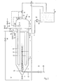
- the filter container consists of a cylinder 1 with a conical base 2 and a cover 3.
- the cover 3 is fastened by a pair of flanges 4 to a cylindrical intermediate part 5, which in turn is connected to the Container 1 is connected by a pair of flanges 6.
- the filter container 1 has in its cylindrical part an inlet line 7 for the slurry and an outlet line 8 for the return.
- the nozzle 9 is used to discharge sludge.
- a control valve 11 and a level control 12 are located in the gas line 10 in the dome-shaped lid 3. Only two lines are shown for ease of illustration. The number of header pipes can be selected according to the boiler size and the required filter area. Filter elements 15 and 15 'are attached to the manifolds.
- Each of the lines 14 and 14 ' has a gas backwash line 31 and 31' which are provided with valves 32 and 32 '.
- the valves 33 and 33 ' serve to shut off the filtrate lines 14 and 14', respectively.
- a tank 34 serves to receive the slurry and is connected via a line 35 to a pump 36 which leads to line 7.
- a riser pipe 41 is additionally fastened between the filter elements 15 in a known manner, starting approximately in the center of the cone 2.
- a pressure line 42 leads to the riser pipe 41, which can be provided with a nozzle 43 at its end.
- the pressure line 42 is provided with a valve 44, which is connected via a supply line to a source of pressurized gas or liquid, not shown.
- Fig. 3 the cone 2 is extended downwards by means of a tubular part 46 via a flange 47.
- the pressure line 42 leads down into the tube part 46.
- Slider 48 is actuated by means of an electric motor 51 and slider 49 is actuated by means of an electric motor 52.
- the slides are actuated by means of electric motors 55 and 56.
- a washing line 42 and 42 'and a ventilation line 53 and 53' lead into each tube part 46.
- 7 sludge is introduced into the filter container 1 via the inlet connection.
- the solids are deposited on the fabrics of the filter elements 15, where they form a solid cake.
- the liquid freed from the solid leaves the container 1 as filtrate via the collecting pipes and their lines 14.
- the upper part of the filter contains an air reserve of approximately 1/6 to 1/4 of the total volume of the filter container 1.
- the liquid level is controlled by the level control 12 kept constant as follows: If the liquid level in the filter container 1 drops, for example during backwashing with air, the exhaust air valve 11 opens until the desired level is reached again. If the liquid level in the container 1 rises, the compressed air valve 30 opens, which is regulated by the level control 12. If the gas pressure in the lid 3 of the container 1 rises above 2 bar, for example, the valve 11 also opens. if and blows off gas to the desired setpoint.
- turbidity is conveyed from the tank 34 into the filter container 1 by means of a pump 36 via the feed line 7. It is filtered at constant pressure.
- a gas pressure of 2 bar prevails in the space above the filter elements 15.
- valve 33 is automatically closed and valve 32, which is connected to a pressure source of, for example, 3 bar, is opened without interrupting the filtration of the other segments.
- Compressed air or another compressed gas penetrates through line 14 and flushes the filter elements 15 of the entire segment free.
- the level controller 12 opens to blow off the inflowing air.
- the pressure is reset to the filtration pressure (2 bar) via a pressure transmitter 37 and the valve 30.
- valve 32 closes again and valve 33 is opened.
- the next row of filter elements can be cleaned in an analogous manner.
- the individual segments are cleaned one after the other as required. If there is a risk of turbidity, the filtrate can be returned to the tank 34 for a short time by opening a valve 38 which is attached in a return line 39.
- the precoating with filter aids can also take place via the feed line 7.
- a preferred embodiment, however, according to FIG. 2, is that thickened residue from the cone 2 of the filter container by means of a mammoth pump consisting of the riser pipe 41 and a gas supplied via the pressure line 42, to which the filter elements 15 are applied.
- a compressed gas for example air or a liquid, for example suspension, can be used as the pressure medium.
- the thickened residue can also be treated in the tube part 46 via line 42 with compressed gas or flushing liquid.
- the residue is whirled up and washed in this way. Then, after opening the slide 48, it can settle down to the slide 49. By closing the slide 48 and opening the slide 49, the cleaned residue that was in the lock 50 can be removed.
- the method according to the invention has proven to be particularly suitable for cleaning brine before and after electrolysis.
- the washing out of sodium hydroxide solution from red mud, the filtration of the viscose from the spinning baths, the condensate cleaning, the filtration of PVC waste water and the filtration of thin juices from the sugar industry also give excellent results.
Landscapes
- Chemical & Material Sciences (AREA)
- Chemical Kinetics & Catalysis (AREA)
- Filtration Of Liquid (AREA)
- Filtering Of Dispersed Particles In Gases (AREA)
- Soy Sauces And Products Related Thereto (AREA)
- Forging (AREA)
- Vehicle Body Suspensions (AREA)
- Paper (AREA)
Abstract
Description
- Die Erfindung betrifft ein Verfahren zur kontinuierlichen Eindickung von Suspensionen in einem Filtereindicker mit kerzenförmigen Filterelementen, die an einzelnen herausnehmbaren Sammelrohren befestigt sind.
- Filtereindicker der Art sind bekannt. So beschreibt die DE-OS 27 41 639 einen Filterbehälter, in welchem Sammelrohre mit hintereinander angeordneten hängenden Filterelementen befestigt sind. Die Sammelrohre liegen nebeneinander auf Stützkörpern und können reihenweise aus dem Filterbehälter herausgenommen werden.
- Aus der AT-PS 211 329 ist eine Anlage zur Rückspülung von reihenweise angeordneten Filterkerzen stehender Bauart bekannt. Die Strangleitungen, auf welchen die Filterelemente befestigt sind, sind beidseitig waagerecht durch die Behälterwand geführt. Die beidseitige Durchführung ist von der Herstellung sehr aufwendig und damit kostspielig. Zusätzlich zu der grossen Anzahl der Kesselbohrungen ist jede Strangleitung mit zwei Absperrorganen versehen, was eine Vielzahl von Ventilen und Armaturen erforderlich macht. Bei allen bekannten Verfahren dieser Art zur Eindickung von Suspensionen mittels Filtereindicker muss nach einem Filtrationszyklus bei Anschwemmung mit Filterhilfsmittel über die Zuleitung Filterhilfsmittel zudosiert werden.
- Aufgabe der Erfindung ist es, ein Verfahren zu schaffen, das die kontinuierliche Eindickung einer Suspension mittels Filtereindicker ermöglicht. Eine weitere Aufgabe ist die Eindickung ohne oder mit minimaler Zugabe von Filterhilfsmitteln.
- Diese Aufgabe wird erfindungsgemäss nach Anspruch 1 gelöst und ist dadurch gekennzeichnet, dass das gasförmige Rückspülmittel über den Filterelementen einen von der Flüssigkeit abgetrennten Gasraum mit einstellbarem Druck bildet.
- Die Erfindung soll anhand von Zeichnungen näher beschrieben werden.
- Es zeigen:
- Fig. 1 Schema des Filtereindickers,
- Fig. 2 Variante des Filtereindickers mit Steigrohr,
- Fig. 3 Variante des Unterteils eines Filtereindickers mit Waschvorrichtung.
- Gemäss Fig. 1 besteht der Filterbehälter aus einem Zylinder 1 mit einem konischen Boden 2 und einem Deckel 3. Der Deckel 3 ist durch ein Flanschenpaar 4 an einem zylindrischen Zwischenteil 5 befestigt, welcher seinerseits mit dem Behälter 1 durch ein Flanschenpaar 6 verbunden ist. Der Filterbehälter 1 weist in seinem zylindrischen Teil eine Zulaufleitung 7 für die Trübe und eine Ablaufleitung 8 für den Rücklauf auf. Der Stutzen 9 dient dem Schlammaustrag. Im domartig gewölbten Deckel 3 befindet sich in der Gasleitung 10 ein Regelventil 11 und eine Niveausteuerung 12. Auf einem Kreisring 13 sind Sammelrohre mit ihren Leitungen 14 und 14' befestigt. Zur einfacheren Darstellung werden nur zwei Leitungen gezeigt. Die Anzahl der Sammelrohre kann entsprechend der Kesselgrösse und der erforderlichen Filterfläche gewählt werden. An den Sammelrohren sind Filterelemente 15 und 15' befestigt. Jede der Leitungen 14 und 14' haben eine Gasrückspülleitung 31 und 31', die mit Ventilen 32 und 32' versehen sind. Die Ventile 33 und 33' dienen zum Absperren der Filtratleitungen 14 bzw. 14'. Ein Tank 34 dient zur Aufnahme der Trübe und ist über eine Leitung 35 mit einer Pumpe 36 verbunden, die auf die Leitung 7 führt.
- In der Variante gemäss Fig. 2 ist zusätzlich ein Steigrohr 41, etwa in der Mitte des Konus 2 beginnend, zwischen den Filterelementen 15 in bekannter Weise befestigt. Zum Steigrohr 41 führt eine Druckleitung 42, welche an ihrem Ende mit einer Düse 43 versehen sein kann. Die Druckleitung 42 ist mit einem Ventil 44 versehen, welches über eine Zufuhrleitung mit einer nicht gezeigten Druckgas-oder Druckflüssigkeitsquelle verbunden ist.
- In Fig. 3 ist der Konus 2 mittels eines Rohrteiles 46 über einen Flansch 47 nach unten verlängert. Die Druckleitung 42 führt nach unten in den Rohrteil 46 hinein. Zwischen dem Schieber 48 und dem Schieber 49 befindet sich eine Schleuse 50. Schieber 48 wird mittels eines Elektromotors 51 und Schieber 49 mittels eines Elektromotors 52 betätigt.
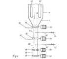
- Gemäss Fig. 4 können zwischen die Schleuse 50 und Rohrteil 46 weitere Rohrteile 46' installiert sein. Die Rohrteile 46, 46' können mittels Schieber 54, 45' und 48 verschlossen werden. Die Schieber werden mittels Elektromotoren 55 und 56 betätigt. In jedes Rohrteil 46 führt eine Waschleitung 42 und 42' sowie eine Entlüftungsleitung 53 bzw. 53'.
- Im Betrieb wird über den Einlaufstutzen 7 Trübe in den Filterbehälter 1 eingeführt. Die Feststoffe lagern sich auf den Geweben der Filterelemente 15 ab, wo sie einen Feststoffkuchen bilden. Die vom Feststoff befreite Flüssigkeit verlässt über die Sammelrohre und deren Leitungen 14 als Filtrat den Behälter 1. Der obere Teil des Filters enthält eine Luftreserve von ca. 1/6 bis 1/4 des Totalvolumens des Filterbehälters 1. Das Flüssigkeitsniveau wird über die Niveausteuerung 12 wie folgt konstant gehalten: Sinkt das Flüssigkeitsniveau im Filterbehälter 1, beispielsweise beim Rückspülen mit Luft ab, so öffnet sich das Abluftventil 11, bis das gewünschte Niveau wieder erreicht ist. Steigt das Flüssigkeitsniveau im Behälter 1, so öffnet das Druckluftventil 30, welches über die Niveausteuerung 12 geregelt wird. Steigt der Gasdruck im Deckel 3 des Behälters 1 beispielsweise über 2 bar, so öffnet das Ventil 11 eben-. falls und bläst Gas bis auf den gewünschten Sollwert ab.
- Während der eigentlichen Filtration wird Trübe aus dem Tank 34 mittels einer Pumpe 36 über die Zulaufleitung 7 in den Filterbehälter 1 gefördert. Es wird bei konstantem Druck filtriert. Die Ventile 33 und 33' sind geöffnet; die Ventile 32 und 32' geschlossen. Im Raum über den Filterelementen 15 herrscht ein Gasdruck von 2 bar. Zur Reinigung beispielsweise des Segmentes, welches mit der Leitung 14 verbunden ist, wird das Ventil 33 automatisch geschlossen und das Ventil 32, welches mit einer Druckquelle von beispielsweise 3 bar verbunden ist, geöffnet, ohne die Filtration der anderen Segmente zu unterbrechen. Druckluft oder ein anderes Druckgas dringt durch die Leitung 14 ein und spült die Filterelemente 15 des ganzen Segmentes frei. Der Niveauregler 12 öffnet, um die einströmende Luft abzublasen. Ueber einen Drucktransmitter 37 und das Ventil 30 wird der Druck wieder auf den Filtrationsdruck (2 bar) eingestellt. Nach beendeter Reinigung schliesst das Ventil 32 wieder und das Ventil 33 wird geöffnet. Auf analoge Weise kann die nächste Reihe von Filterelementen gereinigt werden. Je nach Bedarf werden die einzelnen Segmente hintereinander abgereinigt. Bei Gefahr von Trüblauf kann das Filtrat während kurzer Zeit durch Oeffnen eines Ventils 38, welches in einer Rücklaufleitung 39 angebracht ist, in den Tank 34 zurückgeführt werden. Die Anschwemmung mit Filterhilfsmitteln kann auch über die Zulaufleitung 7 erfolgen.
- Eine vorzugsweise Ausführung besteht jedoch gemäss Fig. 2 darin, dass eingedickter Rückstand aus dem Konus 2 des Filterbehälters mittels einer Mammutpumpe, bestehend aus dem Steigrohr 41 und einem über die Druckleitung 42 zugeführten Gas, auf die Filterelemente 15 auftragen wird. Als Druckmedium kommt ein komprimiertes Gas, beispielsweise Luft oder eine Flüssigkeit, beispielsweise Suspension infrage.
- Nach Fig. 3 kann der eingedickte Rückstand aber auch im Rohrteil 46 über die Leitung 42 mit Druckgas oder Spülflüssigkeit behandelt werden. Dabei wird der Rückstand aufgewirbelt und auf diese Weise gewaschen. Dann kann er sich nach Oeffnen des Schiebers 48 bis auf den Schieber 49 absetzen. Durch Schliessen des Schiebers 48 und Oeffnen von Schieber 49 kann der gereinigte Rückstand, der sich in der Schleuse 50 befand, entnommen werden.
- Nach Fig. 4 sedimentiert bei geöffnetem Schieber 54 und geschlossenem Schieber 54' der von den Filterelementen abgeworfene Feststoff im Rohrteil 46. Zur Auswaschung des Sediments wird Waschflüssigkeit über die Leitung zugeführt und so die Feststoffe aufgewirbelt. Nach dem Absetzen wird der Schieber 54 geschlossen und der Inhalt aus dem Rohrteil 46 durch Oeffnen des Schiebers 54' in das Rohrteil 46' bei geöffneter Entlüftung in der Leitung 53 gefördert. Hier erfolgt eine weitere Waschung über Leitung 42', wobei die Waschflüssigkeit nach oben in das Rohrteil 46 verdrängt wird. Durch Oeffnen des Schiebers 48 wird der Feststoff in die Schleuse gefördert und von dort wie beschrieben ausgetragen. Nun kann der Zyklus wiederholt werden, wobei die zugeführte Waschflüssigkeit jeweils nach oben verdrängt wird und über die Filterelemente das System verlässt.
- Der ganze Betriebsablauf wird über ein Steuergerät geregelt, wobei mehrere Varianten vorgesehen werden können:
- Steuerung über die Zeit nach Erfahrung; Steuerung über die Filtrationsgeschwindigkeit, d.h. bei zu kleinem Durchfluss tritt automatisch die Rückspülung in Funktion; Steuerung über den Rücklauf mittels Trübungsmessung; Steuerung über den Ablauf des Konzentrates mittels Ablaufventil 9 und Timer oder Schlammkonzentrationsmessung; Steuerung über ein Ueberdruckventil 40, das dafür sorgt, dass immer ein Mindestdruck im Kopf des Filterbehälters 1 herrscht; Steuerung der Schieber 48 und 49 über und unter der Schleuse 50 im vorgegebenen Takt.
- Durch den raschen Zyklus der Abreinigung und wieder Inbetriebsetzen der Filterelemente ist in vielen Fällen kein Filterhilfsmittel erforderlich. So hat sich das erfindungsgemässe Verfahren insbesondere zur Reinigung von Sole vor und nach der Elektrolyse als geeignet erwiesen. Aber auch die Auswaschung von Natronlauge aus Rotschlamm, die Filtration der Viskose aus den Spinnbädern, die Kondensatreinigung, Filtration von PVC-Abwasser und die Filtration von Dünnsäften der Zuckerindustrie ergeben ausgezeichnete Resultate.
Claims (16)
Priority Applications (1)
| Application Number | Priority Date | Filing Date | Title |
|---|---|---|---|
| AT82200976T ATE37800T1 (de) | 1981-08-04 | 1982-07-26 | Verfahren zur kontinuierlichen eindickung von suspensionen. |
Applications Claiming Priority (4)
| Application Number | Priority Date | Filing Date | Title |
|---|---|---|---|
| CH501581 | 1981-08-04 | ||
| CH5015/81 | 1981-08-04 | ||
| CH637581 | 1981-10-05 | ||
| CH6375/81 | 1981-10-05 |
Publications (3)
| Publication Number | Publication Date |
|---|---|
| EP0073076A2 true EP0073076A2 (de) | 1983-03-02 |
| EP0073076A3 EP0073076A3 (en) | 1985-04-10 |
| EP0073076B1 EP0073076B1 (de) | 1988-10-12 |
Family
ID=25696758
Family Applications (1)
| Application Number | Title | Priority Date | Filing Date |
|---|---|---|---|
| EP82200976A Expired EP0073076B1 (de) | 1981-08-04 | 1982-07-26 | Verfahren zur kontinuierlichen Eindickung von Suspensionen |
Country Status (8)
| Country | Link |
|---|---|
| US (1) | US4578197A (de) |
| EP (1) | EP0073076B1 (de) |
| AU (1) | AU558413B2 (de) |
| CA (1) | CA1205754A (de) |
| DE (1) | DE3279095D1 (de) |
| ES (1) | ES8307519A1 (de) |
| FI (1) | FI70525C (de) |
| NO (1) | NO156927C (de) |
Cited By (5)
| Publication number | Priority date | Publication date | Assignee | Title |
|---|---|---|---|---|
| WO1992018454A1 (en) * | 1991-04-12 | 1992-10-29 | Amoco Corporation | Process for recovery of purified terephthalic acid |
| WO1992018453A1 (en) * | 1991-04-12 | 1992-10-29 | Amoco Corporation | Process for preparation of terephthalic acid |
| WO1998056487A1 (en) * | 1997-05-22 | 1998-12-17 | Leo Augustinus Schools | Process and device for the filtering of an auxiliary liquid |
| WO2014202690A1 (de) * | 2013-06-18 | 2014-12-24 | Ettlinger Kunststoffmaschinen Gmbh | Austragvorrichtung und austragverfahren |
| CN109260822A (zh) * | 2018-11-02 | 2019-01-25 | 石家庄通过滤器设备制造有限公司 | 一种反清洗过滤器 |
Families Citing this family (7)
| Publication number | Priority date | Publication date | Assignee | Title |
|---|---|---|---|---|
| US5639369A (en) * | 1995-07-14 | 1997-06-17 | W. L. Gore & Associates, Inc. | Filter element |
| JPH09157652A (ja) * | 1995-12-07 | 1997-06-17 | Nitto Denko Corp | 架橋型液晶ポリマー及びその配向フィルム |
| DE10318456B4 (de) * | 2003-04-23 | 2005-03-17 | Grünbeck Wasseraufbereitung GmbH | Filteranlage und Verfahren zum Betreiben einer Filteranlage |
| EP3806975B1 (de) * | 2018-06-13 | 2024-12-04 | Cargill, Incorporated | Filtrationsverfahren |
| WO2022015280A1 (en) * | 2020-07-13 | 2022-01-20 | Evoqua Water Technologies Llc | Regenerative media filter with flow diffuser |
| US11471798B2 (en) * | 2020-11-10 | 2022-10-18 | Regfilter, S.L. | Liquid filtration system |
| US12215555B2 (en) * | 2023-03-21 | 2025-02-04 | Saudi Arabian Oil Company | Systems and methods for operating candle filters to recover glycols from drilling operations |
Family Cites Families (13)
| Publication number | Priority date | Publication date | Assignee | Title |
|---|---|---|---|---|
| AT211329B (de) * | 1959-04-21 | 1960-10-10 | Berkefeld Filter Ges Und Celle | Anlage für die Rückspülung von Filterelementen |
| DE91903C (de) * | 1900-01-01 | |||
| US2661244A (en) * | 1948-06-16 | 1953-12-01 | Paterson Engineering Company L | Means for adding solid materials to liquid |
| US2862622A (en) * | 1955-08-10 | 1958-12-02 | Detrex Chem Ind | Filters |
| US3280978A (en) * | 1964-02-05 | 1966-10-25 | Laval Turbine | Filtering process |
| DE1536782A1 (de) * | 1967-05-30 | 1970-02-12 | Enzinger Union Werke Ag | Verfahren und Vorrichtung zum Entfernen der nach dem Filtrieren in einem Kesselfilter verbleibenden Restfluessigkeit |
| DE2140159C3 (de) * | 1971-08-11 | 1975-07-31 | Braunschweigische Maschinenbauanstalt, 3300 Braunschweig | Kontinuierlich arbeitendes Eindickfilter für die Zuckerindustrie |
| US3891551A (en) * | 1973-09-14 | 1975-06-24 | Sibtec Ab | Method of cleaning a liquid filter, and filter for performing the method |
| JPS5226830B2 (de) * | 1973-10-12 | 1977-07-16 | ||
| FR2251349A1 (en) * | 1973-11-20 | 1975-06-13 | Pepin Fils | Candle-type filters for separation of solids from liquids - with programmed automatic surface cleaning and solids discharge |
| DE2548842C3 (de) * | 1975-10-31 | 1980-03-13 | Passavant-Werke Michelbacher Huette, 6209 Aarbergen | Verfahren und Vorrichtung zum Betrieb einer Filterpresse mit nachgeschaltetem Windkessel |
| NL167857C (nl) * | 1976-09-16 | 1982-02-16 | Chemap Ag | Filtreerinrichting. |
| NO155124C (no) * | 1981-07-16 | 1987-02-18 | Mueller Drm Ag | Gjenvaskbart utfellingsfilter. |
-
1982
- 1982-06-16 NO NO821992A patent/NO156927C/no unknown
- 1982-07-08 FI FI822434A patent/FI70525C/fi not_active IP Right Cessation
- 1982-07-23 US US06/401,322 patent/US4578197A/en not_active Expired - Lifetime
- 1982-07-26 DE DE8282200976T patent/DE3279095D1/de not_active Expired
- 1982-07-26 EP EP82200976A patent/EP0073076B1/de not_active Expired
- 1982-07-29 CA CA000408386A patent/CA1205754A/en not_active Expired
- 1982-08-03 ES ES514688A patent/ES8307519A1/es not_active Expired
- 1982-08-03 AU AU86728/82A patent/AU558413B2/en not_active Ceased
Cited By (9)
| Publication number | Priority date | Publication date | Assignee | Title |
|---|---|---|---|---|
| WO1992018454A1 (en) * | 1991-04-12 | 1992-10-29 | Amoco Corporation | Process for recovery of purified terephthalic acid |
| WO1992018453A1 (en) * | 1991-04-12 | 1992-10-29 | Amoco Corporation | Process for preparation of terephthalic acid |
| SG80528A1 (en) * | 1991-04-12 | 2001-05-22 | Amoco Corp | Process for recovery of purified terephthalic acid |
| SG80548A1 (en) * | 1991-04-12 | 2001-05-22 | Amoco Corp | Process for preparation of terephthalic acid |
| WO1998056487A1 (en) * | 1997-05-22 | 1998-12-17 | Leo Augustinus Schools | Process and device for the filtering of an auxiliary liquid |
| WO2014202690A1 (de) * | 2013-06-18 | 2014-12-24 | Ettlinger Kunststoffmaschinen Gmbh | Austragvorrichtung und austragverfahren |
| US10265649B2 (en) | 2013-06-18 | 2019-04-23 | Ettlinger Kunststoffmaschinen Gmbh | Discharge device and discharge method |
| CN109260822A (zh) * | 2018-11-02 | 2019-01-25 | 石家庄通过滤器设备制造有限公司 | 一种反清洗过滤器 |
| CN109260822B (zh) * | 2018-11-02 | 2021-05-07 | 石家庄一通过滤器设备制造有限公司 | 一种反清洗过滤器 |
Also Published As
| Publication number | Publication date |
|---|---|
| ES514688A0 (es) | 1983-08-01 |
| NO156927C (no) | 1987-12-23 |
| DE3279095D1 (en) | 1988-11-17 |
| NO156927B (no) | 1987-09-14 |
| CA1205754A (en) | 1986-06-10 |
| ES8307519A1 (es) | 1983-08-01 |
| AU8672882A (en) | 1983-03-03 |
| AU558413B2 (en) | 1987-01-29 |
| NO821992L (no) | 1983-02-07 |
| FI822434A0 (fi) | 1982-07-08 |
| US4578197A (en) | 1986-03-25 |
| FI822434L (fi) | 1983-02-05 |
| EP0073076B1 (de) | 1988-10-12 |
| FI70525B (fi) | 1986-06-06 |
| FI70525C (fi) | 1986-09-24 |
| EP0073076A3 (en) | 1985-04-10 |
Similar Documents
| Publication | Publication Date | Title |
|---|---|---|
| EP0070589B1 (de) | Rückspüllbares Kerzenanschwemmfilter | |
| EP0291538B1 (de) | Verfahren und Vorrichtung zum kontinuierlichen Filtrieren von Flüssigkeiten | |
| DE2161883A1 (de) | Verfahren zum Filtrieren einer Flüssigkeit und Einrichtung zum Durchführen des Verfahrens | |
| EP0073076B1 (de) | Verfahren zur kontinuierlichen Eindickung von Suspensionen | |
| EP0174554A1 (de) | Wärmeaustauscher zum Übertragen von Wärme aus Abwasser | |
| DE1811507A1 (de) | Verfahren und Vorrichtung zum Abscheiden suspendierter fester Stoffe aus Fluessigkeiten | |
| DE1611158C3 (de) | Filtereinrichtung | |
| EP0064795B1 (de) | Verfahren zur kontinuierlichen Eindickung von Suspensionen | |
| DE1461395C3 (de) | Steuereinrichtung für die Flüssigkeitsströme in einer Filteranlage | |
| CH618666A5 (en) | Process for purifying or treating waste water and plant for carrying out this process | |
| EP0412173A1 (de) | Verfahren und Anlage zur Aufbereitung und Reinigung von Abwasser | |
| DE2247240A1 (de) | Flotationsanlage | |
| DE3879655T2 (de) | Rueckspuelsystem fuer eindicker. | |
| DE2555850C3 (de) | Verfahren zum Filtrieren einer Suspension | |
| DE1611073A1 (de) | Verfahren und Vorrichtung zur selbsttaetigen Schnellfilterwaesche | |
| DE2104861B2 (de) | Verfahren und Vorrichtung zur kontinuierlichen Filtration von Flüssigkeiten | |
| DE102005033314A1 (de) | Verfahren und Filteranlage zum Filtern von Rohwasser | |
| CH313293A (de) | Einrichtung zum Filtrieren von Flüssigkeiten | |
| DE2044319A1 (en) | Effluent treatment - by combined flotation/sedimentation and filtration | |
| DE19939679C2 (de) | Abwasserreinigungsvorrichtung mit Feststoffakkumulation | |
| DE202005011219U1 (de) | Filteranlage zum Filtern von Rohwasser | |
| DE3432377A1 (de) | Verfahren zum kontinuierlichen filtern von fluessigkeiten | |
| DE55132C (de) | Filter mit selbstthätiger Auswaschung des Filtermaterials | |
| DE308728C (de) | ||
| DE886726C (de) | Verfahren und Vorrichtung zum stufenweisen Waschen von in Klaerbecken abgesetztem Abwasserschlamm |
Legal Events
| Date | Code | Title | Description |
|---|---|---|---|
| PUAI | Public reference made under article 153(3) epc to a published international application that has entered the european phase |
Free format text: ORIGINAL CODE: 0009012 |
|
| AK | Designated contracting states |
Designated state(s): AT BE CH DE FR GB IT LI LU NL SE |
|
| PUAL | Search report despatched |
Free format text: ORIGINAL CODE: 0009013 |
|
| AK | Designated contracting states |
Designated state(s): AT BE CH DE FR GB IT LI LU NL SE |
|
| 17P | Request for examination filed |
Effective date: 19850611 |
|
| GRAA | (expected) grant |
Free format text: ORIGINAL CODE: 0009210 |
|
| AK | Designated contracting states |
Kind code of ref document: B1 Designated state(s): AT BE CH DE FR GB IT LI LU NL SE |
|
| REF | Corresponds to: |
Ref document number: 37800 Country of ref document: AT Date of ref document: 19881015 Kind code of ref document: T |
|
| REF | Corresponds to: |
Ref document number: 3279095 Country of ref document: DE Date of ref document: 19881117 |
|
| GBT | Gb: translation of ep patent filed (gb section 77(6)(a)/1977) | ||
| ET | Fr: translation filed | ||
| ITF | It: translation for a ep patent filed | ||
| PLBE | No opposition filed within time limit |
Free format text: ORIGINAL CODE: 0009261 |
|
| STAA | Information on the status of an ep patent application or granted ep patent |
Free format text: STATUS: NO OPPOSITION FILED WITHIN TIME LIMIT |
|
| 26N | No opposition filed | ||
| ITTA | It: last paid annual fee | ||
| EPTA | Lu: last paid annual fee | ||
| EAL | Se: european patent in force in sweden |
Ref document number: 82200976.7 |
|
| PGFP | Annual fee paid to national office [announced via postgrant information from national office to epo] |
Ref country code: FR Payment date: 19970613 Year of fee payment: 16 |
|
| PGFP | Annual fee paid to national office [announced via postgrant information from national office to epo] |
Ref country code: AT Payment date: 19970616 Year of fee payment: 16 |
|
| PGFP | Annual fee paid to national office [announced via postgrant information from national office to epo] |
Ref country code: BE Payment date: 19970617 Year of fee payment: 16 |
|
| PGFP | Annual fee paid to national office [announced via postgrant information from national office to epo] |
Ref country code: SE Payment date: 19970618 Year of fee payment: 16 |
|
| PGFP | Annual fee paid to national office [announced via postgrant information from national office to epo] |
Ref country code: GB Payment date: 19970620 Year of fee payment: 16 |
|
| PGFP | Annual fee paid to national office [announced via postgrant information from national office to epo] |
Ref country code: DE Payment date: 19970623 Year of fee payment: 16 |
|
| PGFP | Annual fee paid to national office [announced via postgrant information from national office to epo] |
Ref country code: NL Payment date: 19970630 Year of fee payment: 16 |
|
| PGFP | Annual fee paid to national office [announced via postgrant information from national office to epo] |
Ref country code: LU Payment date: 19970908 Year of fee payment: 16 |
|
| PGFP | Annual fee paid to national office [announced via postgrant information from national office to epo] |
Ref country code: CH Payment date: 19971021 Year of fee payment: 16 |
|
| PG25 | Lapsed in a contracting state [announced via postgrant information from national office to epo] |
Ref country code: LU Free format text: LAPSE BECAUSE OF NON-PAYMENT OF DUE FEES Effective date: 19980726 Ref country code: GB Free format text: LAPSE BECAUSE OF NON-PAYMENT OF DUE FEES Effective date: 19980726 Ref country code: AT Free format text: LAPSE BECAUSE OF NON-PAYMENT OF DUE FEES Effective date: 19980726 |
|
| PG25 | Lapsed in a contracting state [announced via postgrant information from national office to epo] |
Ref country code: SE Free format text: LAPSE BECAUSE OF NON-PAYMENT OF DUE FEES Effective date: 19980727 |
|
| PG25 | Lapsed in a contracting state [announced via postgrant information from national office to epo] |
Ref country code: LI Free format text: LAPSE BECAUSE OF NON-PAYMENT OF DUE FEES Effective date: 19980731 Ref country code: CH Free format text: LAPSE BECAUSE OF NON-PAYMENT OF DUE FEES Effective date: 19980731 Ref country code: BE Free format text: LAPSE BECAUSE OF NON-PAYMENT OF DUE FEES Effective date: 19980731 |
|
| BERE | Be: lapsed |
Owner name: MULER A.G. Effective date: 19980731 |
|
| PG25 | Lapsed in a contracting state [announced via postgrant information from national office to epo] |
Ref country code: NL Free format text: LAPSE BECAUSE OF NON-PAYMENT OF DUE FEES Effective date: 19990201 |
|
| REG | Reference to a national code |
Ref country code: CH Ref legal event code: PL |
|
| GBPC | Gb: european patent ceased through non-payment of renewal fee |
Effective date: 19980726 |
|
| EUG | Se: european patent has lapsed |
Ref document number: 82200976.7 |
|
| PG25 | Lapsed in a contracting state [announced via postgrant information from national office to epo] |
Ref country code: FR Free format text: LAPSE BECAUSE OF NON-PAYMENT OF DUE FEES Effective date: 19990331 |
|
| NLV4 | Nl: lapsed or anulled due to non-payment of the annual fee |
Effective date: 19990201 |
|
| PG25 | Lapsed in a contracting state [announced via postgrant information from national office to epo] |
Ref country code: DE Free format text: LAPSE BECAUSE OF NON-PAYMENT OF DUE FEES Effective date: 19990501 |
|
| REG | Reference to a national code |
Ref country code: FR Ref legal event code: ST |