EP0071902A2 - Machine-outil pour bricoleur, notamment scie circulaire basculante avec porte-pièce - Google Patents
Machine-outil pour bricoleur, notamment scie circulaire basculante avec porte-pièce Download PDFInfo
- Publication number
- EP0071902A2 EP0071902A2 EP82106883A EP82106883A EP0071902A2 EP 0071902 A2 EP0071902 A2 EP 0071902A2 EP 82106883 A EP82106883 A EP 82106883A EP 82106883 A EP82106883 A EP 82106883A EP 0071902 A2 EP0071902 A2 EP 0071902A2
- Authority
- EP
- European Patent Office
- Prior art keywords
- console
- support legs
- protective box
- screwed
- rocker
- Prior art date
- Legal status (The legal status is an assumption and is not a legal conclusion. Google has not performed a legal analysis and makes no representation as to the accuracy of the status listed.)
- Granted
Links
Images


Classifications
-
- B—PERFORMING OPERATIONS; TRANSPORTING
- B27—WORKING OR PRESERVING WOOD OR SIMILAR MATERIAL; NAILING OR STAPLING MACHINES IN GENERAL
- B27G—ACCESSORY MACHINES OR APPARATUS FOR WORKING WOOD OR SIMILAR MATERIALS; TOOLS FOR WORKING WOOD OR SIMILAR MATERIALS; SAFETY DEVICES FOR WOOD WORKING MACHINES OR TOOLS
- B27G19/00—Safety guards or devices specially adapted for wood saws; Auxiliary devices facilitating proper operation of wood saws
- B27G19/02—Safety guards or devices specially adapted for wood saws; Auxiliary devices facilitating proper operation of wood saws for circular saws
- B27G19/04—Safety guards or devices specially adapted for wood saws; Auxiliary devices facilitating proper operation of wood saws for circular saws for manually-operated power-driven circular saws
-
- B—PERFORMING OPERATIONS; TRANSPORTING
- B23—MACHINE TOOLS; METAL-WORKING NOT OTHERWISE PROVIDED FOR
- B23Q—DETAILS, COMPONENTS, OR ACCESSORIES FOR MACHINE TOOLS, e.g. ARRANGEMENTS FOR COPYING OR CONTROLLING; MACHINE TOOLS IN GENERAL CHARACTERISED BY THE CONSTRUCTION OF PARTICULAR DETAILS OR COMPONENTS; COMBINATIONS OR ASSOCIATIONS OF METAL-WORKING MACHINES, NOT DIRECTED TO A PARTICULAR RESULT
- B23Q1/00—Members which are comprised in the general build-up of a form of machine, particularly relatively large fixed members
- B23Q1/01—Frames, beds, pillars or like members; Arrangement of ways
-
- B—PERFORMING OPERATIONS; TRANSPORTING
- B27—WORKING OR PRESERVING WOOD OR SIMILAR MATERIAL; NAILING OR STAPLING MACHINES IN GENERAL
- B27B—SAWS FOR WOOD OR SIMILAR MATERIAL; COMPONENTS OR ACCESSORIES THEREFOR
- B27B5/00—Sawing machines working with circular or cylindrical saw blades; Components or equipment therefor
- B27B5/16—Saw benches
- B27B5/22—Saw benches with non-feedable circular saw blade
- B27B5/224—Saw benches with non-feedable circular saw blade the workpieces being fitted on a pivoting support
Definitions
- the invention relates to a metal-cutting do-it-yourself machine, in particular a rocking saw, consisting of a motor console, a protective box for the tool, support legs and struts, which together form a frame and are screwed together.
- Do-it-yourself machines are subject to special requirements with regard to weight, handling, mountability and safety devices. Not to forget the problems with packaging size and corrosion protection. Do-it-yourself machines must be light in weight so that they can be easily transported from one place to another. At the same time, however, a high level of stability in connection with vibration insensitivity is required. This includes that such a machine should have as little noise as possible, e.g. Rattling and rattling noises generated.
- Do-it-yourself machines can also cost little, which is why the shipping and storage costs have to be reduced. Also for cost reasons, assembly work at the manufacturer should be avoided as far as possible. In this context, the problem is the required, as cheap as possible corrosion protection, which requires post-treatment during welding, e.g. necessary by painting. The problem of accident safety also arises with do-it-yourself machines. It cannot be ruled out that laypersons who do not know about the relevant safety regulations work with such a device. In circular saws, for example, numerous accidents happen every year that justify the demand for "foolproof" machines.
- the German utility model 18 46 200 is known as prior art, in which a multi-purpose device for sawing, planing, drilling, etc. is disclosed.
- the frame of this device is constructed from angle brackets or tubes that can be assembled and screwed together to make it easier to convert.
- the angle irons form a frame from which the legs protrude vertically downwards.
- the construction has the disadvantage that many struts are required for stabilization, whereby a framework is formed. Although this is necessary because of the universal adjustability of the device, it also causes a not inconsiderable increase in space and weight. In addition, no safety devices are disclosed.
- a circular saw with screwed-on support legs is known from its own utility model 79 19 012.
- parts of the frame are still welded here, which requires special corrosion protection measures, such as Painting is necessary.
- many parts have to be preassembled by the welded joints, which limits the size of the packaging.
- German patent specification 572 481 discloses a circular saw with a stationary, rotating saw blade and a pivotable feed device in the form of a rocker.
- the disadvantage of this construction lies in the inadequate safety devices and the vibration sensitivity of the construction.
- the receiving tray for the sawdust e.g. Beams, tree trunks, etc. have the shape of a V, which limits the maximum possible diameter of the sawn material.
- this construction is welded in many places and is therefore not intended for self-assembly.
- the present invention is based on the object of providing a metal-cutting do-it-yourself machine which is lightweight, stable, vibration-stable, corrosion-protected, easy to assemble, low-noise and accident-proof and can be supplied with little packaging space.
- a motor console which consists of a hood-like Bloch housing which is formed by a stamped sheet metal plate with obtuse-angled edges which only abut loosely.
- Support legs are also provided, whose L-shaped profile and a wedge-shaped contour tapering from top to bottom. Two of these support legs are screwed into the corners of the motor console under the flat contact of their two legs. Two support legs, each with an L-leg, rest on two opposite console walls and are screwed to them.
- a protective case for a tool, in particular a saw blade lies flat against a console wall and is directly or indirectly screwed to it and two support legs.
- This shape of the frame construction results in a stable and vibration-stable construction despite the use of thin, bent sheets.
- the angle at which the legs of the support leg profiles are in relation to each other corresponds to the solid angle which the abutting console walls form with one another.
- These abutting console walls are not directly connected to each other, e.g. connected by a weld. You get their stabilizing bond by screwing two support legs preferably to the inside of the corners formed by the console walls.
- the specified bending angles of sheet metal profiles can never be exactly adhered to in practice. Since the support legs are screwed to the corner-forming console walls and the angles never exactly match, these parts have to deform a little to get to the system, which creates a pre-stressed bond that helps stabilize the frame. Due to the preferably obtuse-angled bend of three of the four console walls and the flat contact of the support legs in the console corners, the support legs project obliquely downward, which increases the stability of the frame. Two of the support legs are screwed to the motor console with only one leg, which preferably lies flat against the inside of two console walls. These legs also protrude outwards.
- the fourth console wall facing the saw blade is bent downwards at a right angle.
- This protective box is screwed on the one hand to the said console wall and on the other hand preferably to a bearing strut which connects the two support legs screwed on with only one leg. The remaining support legs are also connected and screwed to one another and to the latter two by struts.
- This type of frame assembly using only thin, bent sheet metal profiles enables a lightweight, yet torsionally stiff, stable and vibration-stable frame construction that has no welded connections, but only screw connections.
- the support legs preferably have screwed-on foot plates at their lower end, which are also a stamped and bent part made of galvanized sheet metal. These feet preferably have punched-out tabs which are bent upwards at an angle of inclination of the support legs against the floor, which lie flat against the legs of the support leg profile and are screwed there to said legs by means of eyes which are also punched out.
- the use of such foot plates is not limited to machine tool frames, but includes all types of feet or legs, multi-legged or even arched leg profiles also being possible.
- the shape of the die cut that defines the flaps changes accordingly. The number of lobes, as well as their shape, triangular, polygonal, oval, etc., is also not specified. For all sheet metal parts, it does not necessarily have to be stamped, stamping is only a cheap way of producing, which may can take place simultaneously with the bending.
- the punching task can also be solved by electrochemical erosion, separation welding, etc.
- the protective box for the cutting tool here preferably a saw blade
- the protective box for the cutting tool is not easily accessible for lightweight construction because of the strong vibrations that are caused, among other things, by the shape of the tool.
- the protective box consists of a box and a lid, it is difficult to eliminate vibratory noise caused by rattling or rattling.
- This problem is solved according to the invention in that the protective box on the Side walls preferably have punched-out and bent-out clamping lugs or claws, the side walls of the wider protective box cover engaging in the space between the clamping lugs and the side wall of the protective box. These clamping lugs are only connected to the protective box on one side and can therefore yield slightly under pressure.
- the side walls of the protective box cover are supported on the clamping lugs and are also laterally clamped by these against the side walls of the protective box.
- the protective case cover is pressed against the clamping lugs by screws and since these give way somewhat elastically, the side walls of the protective case cover lie against all the lugs at the same time, whereby this connection of protective case and protective case cover can be slightly pretensioned by the screws. Firstly, this means that the screws can no longer loosen so easily, and secondly, relative movements between the protective box and the protective box cover are avoided, which would lead to undesirable rattling noises.
- the protective box and its cover are also stamped and bent parts made of galvanized sheet metal.
- the metal-cutting do-it-yourself machine tool is preferably designed as a rocking saw with a specially shaped receptacle for the sawdust.
- the receiving trough has the shape of a U, the U-leg of the receiving trough which is adjacent to the saw blade being bent toward the saw blade at approximately half the height.
- This shape of the receptacle has the advantage over a normal U or V shape that there is a large opening width even at a low height above the horizontal web of the cranked U. This means that thick bars, e.g. B.
- the cranked U-shape enables a deep layer of such a thick beam, which, if not in one cut, can be sawn through in several cuts.
- the bar must be rotated a little further after each feed movement, since the saw blade only saws out one sector, which, however, extends over the central axis of the bar.
- a correspondingly wide-opening V-shape does not serve the same purpose, because in this case the leg on the saw blade side, which runs flat, would hit the motor or the frame after a short swivel path.
- the flat upper part of the cranked U-leg is higher and allows larger swivel angles of the rocker. With this shape of the receptacle, beams up to a thickness of approx. 15 cm can be sawn through in one cut.
- a safety device which always tries to pivot the rocker back into its rest position.
- a control rod is pivotally attached to the rocker, the opposite side of which forms a U-shaped clamping spring.
- This clamping spring is normally immovably stuck in an opening in the motor console.
- the control rod passes the clamping spring through an opening in the crossbar of its U-profile. Behind the clamping spring inside the motor console there is a large washer and a nut on the control rod, the nut forming an abutment for the washer.
- a compression spring is guided on the control rod, which is supported on the one hand on the clamping spring and on the other hand on a disk which is also guided on the control rod. Is by a swivel movement of the When the saw is fed into the rocker, the control rod also moves in the direction of the saw blade or motor console through the hole in the clamping spring. As a result, the compression spring is tensioned and, when the rocker is released, automatically swivels it into its rest or initial position, where the saw blade is secured against access on all sides. Without this safety device, the rocker would tilt due to its own weight towards the saw blade, which would then protrude openly into this tray if the receiving tray was empty.
- the clamping spring has waists with which it snaps into the console wall.
- the rocker To change the saw blade, the rocker must be pivoted slightly beyond the rest position so that the aprons attached to the receiving tray release the saw blade.
- the clamping spring can be disengaged, which allows the rocker to pivot backwards with the control rod, but only until the large disk in question, which cannot pass through the opening in the motor console, lies against the console wall and over the nut the control rod and thus the rocker holds back.
- the compression spring pushes the clamping spring back into the console wall, where it automatically engages again. This has the advantage that the safety device cannot be put out of operation unintentionally or through negligence.
- an upper blade guard is provided for the saw blade, which is pivotally attached to the protective box.
- This blade guard has a preferably curved sliding plate on its rocker-side end.
- a return spring is also provided for the upper blade guard. When sawing thick beams, they push the sliding plate and thus the upper blade guard upwards against the force of the return spring. If the rocker swings back again, the return spring pulls the upper blade guard back into its rest position. This is also the case with Sawing thick beams, which due to the feeding swiveling movement hit the saw blade more from above, ensures that the saw blade is completely covered upwards.
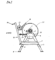
- FIG. 1 shows a side view of a rocking saw, in which the protective covers for the saw blade 22 are not shown for better clarity.
- a motor 1 drives directly through its stub shaft a round saw blade 22.
- An electric motor for 220 volt alternating current is preferably used.
- the motor 1 is screwed onto a hood-like motor console 2, which consists of a galvanized sheet metal plate with edges bent downwards on all sides.
- the middle, horizontal part of the sheet metal plate forms the console base 3 and the bent edges form the console walls 4, 4a, which only loosely abut against one another with their lateral edges and are not directly connected to one another, for example by a weld seam.
- the console wall 4a against which the protective box 23 for the saw blade 22 lies flat, is bent vertically downward from the console base 3.
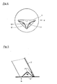
- the other console walls 4, as shown in FIG. 8, form an angle of preferably more than 90 ° with the console base 3.
- the motor console 2 rests on support legs 5 made of galvanized sheet steel, with which it is screwed.
- the support legs 5 are L-shaped in cross-sectional profile and have a contour which tapers in the longitudinal direction from top to bottom in a wedge shape.
- the support legs 5 preferably also have embossed beads which increase stability.
- FIG. 3 shows the assignment of the support legs 5 to the motor console 2.
- the two support legs 5 adjacent to the saw blade 22 lie flat with one of their L-legs on the inside of each console wall 4 and are screwed to it.
- the attachment points are located approximately halfway along the length of the console walls 4.
- the two other support legs 5 are screwed onto the inside of the corners of the motor console 2 facing away from the saw blade 22.
- the angle at which the L-legs of the support legs 5 are in relation to one another corresponds to the solid angle which the console walls 4 forming the two corners enclose with one another. For this reason, the support legs 5 nestle flat against the inside of the console walls 4. Since the angle between the console base 3 and the three console walls 4 is preferably greater than 90 °, the support legs 5, which form an extension of the console walls 4 by their flat contact, extend obliquely outwards.
- the support legs 5 are connected and screwed to their neighboring legs by struts 6 or bearing struts 7. These profiled struts 6,7 are also punched and bent from galvanized sheet metal.
- a foot plate 8 is adapted and screwed to each support leg 5.
- This base plate 8 is also a stamped and bent part made of galvanized sheet metal.
- FIG. 4 shows the die cut for a base plate 8.
- the base plate 8 has a T-shaped cut 9 and two or more eyes 10.
- the T-cut 9 forms two triangular flaps 11 in connection with the two dashed bending lines 12, which are bent obliquely upwards after the punching along the bending lines 12.
- the angle between the tabs 11 and the horizontal foot plate 8 is the same as the angle that the obliquely outwardly extending support leg 5 includes with the horizontal.
- Figure 5 illustrates that the correspondingly obliquely cut off support leg 5 at its lower end stands flat on the base plate 8 and that the tabs 11 lie flat against the inside of the legs of the support leg 5 due to the same angle.
- the round shape of the eyes 10 is retained, so that the tabs 11 can be screwed exactly to the legs of the support legs 5.
- the connecting screws are only subjected to tension and not to thrust, since the thrust-generating Aulfag forces are directed directly from the plate 8 to the support legs 5 and only the tensile or pressure-generating cornering forces are guided by the tabs 11 via the connecting screws onto the legs of the support legs 5.
- the protective box 23 is screwed to the motor console 2 and a bearing strut 7.
- the protective box 23 has punched-out and bent-out clamping lugs 25 on its two side walls.
- the protective box cover 24 is somewhat wider than the protective box 23, so that it can be pushed over the protective edges of the box 23.
- the edges of the side walls of the protective box cover 24 engage in the space between the clamping lugs 25 and the side walls of the protective box 23.
- FIG. 7 this engagement position is shown in cross section ⁇ .
- the protective box cover 24 is pressed against the clamping lugs 25 of the protective box 23 by means of screws and wing nuts 26. Since the clamping lugs 25 give way slightly under pressure, the protective cover 24 is supported on all the lugs at the same time. This connection is pre-tensioned by the screws mentioned above and therefore cannot generate rattling bushes even with strong vibrations.
- the space between the clamping lugs 25 and the side walls of the protective box 23 is dimensioned so enq that the side walls of the protective box cover are clamped therein and thus have no freedom of movement to the side.
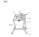
- the feed device for the sawing material is designed in the form of a rocker 13 which is pivotably articulated on the two bearing struts 7.
- FIG. 6 shows a perspective view of the rocker 13, which consists of two U-profiles 14, 15 which are open towards the saw blade 22 and which have at their upper ends the wide part 16a of a retaining plate 16 are connected.
- a narrow part 16b of the retaining plate 16 is fastened in alignment with the wide part 16a.
- the wide part 18a of the saw table 18 is also fastened between the two U-profiles 14, 15 and also has a narrow part 18b on the other side of the U-profile 15.
- a gap 17 with the width of the U-profile 15 is created.
- Both sides of the gap 17 are at the wide part 18a and attached to the narrow part 18b of the saw table 18 cover aprons 20.
- the cover aprons 20 and the U-profile 15 open towards the saw blade 22 thus form a shaft through which the sawdust is discharged downwards.
- the U-profile 15 also functions as a rocker-side saw blade cover.
- the saw table 18 forms, together with the retaining plate 16, a trough 21 for receiving the material to be sawn.
- this tub 21 has a special shape. In cross section, it corresponds approximately to a U, the leg of the U closest to the saw blade 22 being angled in the upper part to the saw blade 22.
- the web and the cranked leg of the U are preferably formed by the saw table 18.
- This shape of the receiving trough 21 has the advantage that, as shown in FIG. 1, bars or rods up to a diameter of approximately 15 cm in the lower part of the U- store shaped receptacle 21 and can be sawn through in one cut.
- the cranked U-shape increases the opening width of the receiving trough 21 so that even very thick bars come to lie relatively deep in the receiving trough 21. Due to the deep position in the receiving trough 21, the cut of the saw blade 22 extends beyond the center line of the beam, even with thick beams. If you do not want to saw such thick bars, you can instead the diameter of the because of the advantageous shape of the receiving tray 21 Saw blade:, reduce 22. The reduction in the size of the saw blade 22 allows the use of a relatively low-power electric motor that can be connected to 220 volt alternating current.
- a handle 19 is attached to the upper part of the rocker 13. Almost all parts of the rocker 13 are stamped and bent parts made of galvanized sheet metal, which are only connected to one another by screws.
- an upper blade guard 27 is provided, which has a preferably curved sliding plate 28 on its front side and is pivotally attached to the protective box 23 on its rear side. If a thick Ualken is fed on the rocker 13, this pushes the sliding plate 28 and thus the upper blade guard 27 upwards. This takes place against the force of a spring, not shown, which automatically brings the upper blade guard 27 back into its cow position.
- a safety device 29 is indicated in FIG. 1, which closes the rocker 13 from each feed position into the starting or rest position. swings back. 8 and 9, the safety device 29 is shown schematically in detail. It consists of a control rod 30 which is pivotally attached to the rocker 13. On the control rod 30, a compression spring 32 is guided, which is supported on the one hand on a disc 31 and on the other hand on a bracket 35 in the form of a clamping spring which is mounted in a fixed manner in the console wall 4. The rod 30 passes through the clamping spring 35 through a bore 38 (see FIG. 9) and has a large disk 33 and a nut 34 behind it. With a swivel movement of the rocker 13, the control rod 30 is pushed through the opening 38 in the clamping spring 35, whereby the compression spring 32 is tensioned and develops resilient spring forces.
- FIG. 9 shows a perspective view of this clamping spring 35. It is a stamped, bent and galvanized sheet metal part in the manner of a U-shaped bracket. On the two legs of the clamping spring 35, waists 36 are attached at different distances from the crossbar, which serve to fasten the clamping spring in the console wall 4.
- the web of the U-shaped clamping spring 35 is also provided with a bore 38 through which the control rod 30 protrudes.
- FIG. 3 shows an opening 37 in the console wall 4 facing the viewer. The clamping spring 35 is inserted into this cruciform opening 37.
- the normal bracket width of the clamping spring 35 corresponds to the maximum width of the cruciform opening 37
- the bracket width of the clamping spring 35 at the height of the waists 36 corresponds to the width of the vertical legs of the cruciform opening 37.
- the opening width of the clamping spring 35 measured between the two waists 36, is greater than the height of the vertical cross leg of the opening 37.
- the thickness of the waists 36 corresponds to the wall thickness of the console wall 4.
- the clamping spring 35 is immovably clamped in the opening 37, since it is in front of and behind the waist 36 has its full bracket width again and abuts at these points on the inside and outside of the console wall 4.
- the console wall 4 thus engages in the waists 36 of the clamping spring 35 like a toothing.
- the pivoting path of the rocker 13 backwards is restricted.
- the cover aprons 20 (see FIG. 2) attached to the parts 18a 'and 18b of the saw table 18 must be at least partially removed.
- the rocker 13 must be pivoted backwards beyond its rest position.
- the disk 33 which is so large that it cannot pass through the opening 37 in the console wall 4. If it comes to rest against the console wall 4, it holds the control rod 30 back via the nut 34. If the rocker 30 is swung forward again in the direction of the saw blade 22 the compression spring 32 pushes the clamping spring 35 back into its locking position in the motor console 2.
- the safety device 29 cannot be put out of operation by mistake.
Landscapes
- Life Sciences & Earth Sciences (AREA)
- Engineering & Computer Science (AREA)
- Mechanical Engineering (AREA)
- Wood Science & Technology (AREA)
- Forests & Forestry (AREA)
- Sawing (AREA)
- Food-Manufacturing Devices (AREA)
- Harvester Elements (AREA)
Priority Applications (1)
| Application Number | Priority Date | Filing Date | Title |
|---|---|---|---|
| AT82106883T ATE18733T1 (de) | 1981-08-07 | 1982-07-30 | Spanabhebende heimwerkermaschine, insbesondere wippsaege. |
Applications Claiming Priority (2)
| Application Number | Priority Date | Filing Date | Title |
|---|---|---|---|
| DE8123262U | 1981-08-07 | ||
| DE19818123262U DE8123262U1 (de) | 1981-08-07 | 1981-08-07 | Spanabhebende heimwerkermaschien, insbesondere wippsaege |
Publications (3)
| Publication Number | Publication Date |
|---|---|
| EP0071902A2 true EP0071902A2 (fr) | 1983-02-16 |
| EP0071902A3 EP0071902A3 (en) | 1983-07-20 |
| EP0071902B1 EP0071902B1 (fr) | 1986-03-26 |
Family
ID=6730210
Family Applications (1)
| Application Number | Title | Priority Date | Filing Date |
|---|---|---|---|
| EP82106883A Expired EP0071902B1 (fr) | 1981-08-07 | 1982-07-30 | Machine-outil pour bricoleur, notamment scie circulaire basculante avec porte-pièce |
Country Status (3)
| Country | Link |
|---|---|
| EP (1) | EP0071902B1 (fr) |
| AT (1) | ATE18733T1 (fr) |
| DE (2) | DE8123262U1 (fr) |
Cited By (5)
| Publication number | Priority date | Publication date | Assignee | Title |
|---|---|---|---|---|
| AT400938B (de) * | 1994-11-28 | 1996-04-25 | Putz Stefan | Brennholzkreissäge |
| EP1878548A1 (fr) | 2006-07-11 | 2008-01-16 | Scheppach Fabrikation von Holzbearbeitungsmaschinen GmbH | Scie circulaire pour bois de chauffage |
| CN102528469A (zh) * | 2012-03-02 | 2012-07-04 | 青岛地恩地机电科技股份有限公司 | 机床支架 |
| CN111250783A (zh) * | 2020-03-26 | 2020-06-09 | 广东电科院能源技术有限责任公司 | 一种电锯和适用于机器人的电锯设备 |
| EP3693143A1 (fr) * | 2019-02-08 | 2020-08-12 | Scheppach Fabrikation von Holzbearbeitungsmaschinen GmbH | Scie circulaire à berceau basculant |
Families Citing this family (3)
| Publication number | Priority date | Publication date | Assignee | Title |
|---|---|---|---|---|
| CN110587023B (zh) * | 2019-08-29 | 2024-12-10 | 安徽艾嘉门窗有限公司 | 一种用于45度角自动切割单支门窗铝塑型材的加工中心 |
| CN114789341B (zh) * | 2022-03-09 | 2023-05-02 | 无锡威卡威汽车零部件有限公司 | 一种用于侧梁的双头锯铣机器人 |
| CN119839539B (zh) * | 2025-03-21 | 2025-05-27 | 四川筑盾人防工程设备有限公司 | 一种临时支墩制作焊接设备 |
Family Cites Families (7)
| Publication number | Priority date | Publication date | Assignee | Title |
|---|---|---|---|---|
| FR965169A (fr) * | 1950-09-05 | |||
| DE494472C (de) * | 1929-01-13 | 1930-03-24 | Mathias De Zurik | Verfahren und Vorrichtung zum Entfernen unerwuenschter Teile, wie eingewachsene AEste, Rinde u. dgl., aus einem Holzkoerper, der zur Herstellung von Holzschliff dienen soll |
| FR989220A (fr) * | 1944-02-16 | 1951-09-06 | Carter de protection à mâchoires ouvrantes pour outil, notamment pour une scie rotative | |
| US3081841A (en) * | 1962-04-03 | 1963-03-19 | Thomas J Mauro | Sheet metal legs |
| DE1453033A1 (de) * | 1963-06-20 | 1969-01-02 | Lutz Kg | Kreissaege |
| DE2011033A1 (de) * | 1970-03-09 | 1971-09-23 | Hempelmann W | Verstrebung fur Standbeine \on Maschinen, insbesondere Tischkreissagen |
| USRE30689E (en) * | 1976-09-14 | 1981-07-28 | Foldable bench for a portable hand-held circular saw |
-
1981
- 1981-08-07 DE DE19818123262U patent/DE8123262U1/de not_active Expired
-
1982
- 1982-07-30 EP EP82106883A patent/EP0071902B1/fr not_active Expired
- 1982-07-30 DE DE8282106883T patent/DE3270104D1/de not_active Expired
- 1982-07-30 AT AT82106883T patent/ATE18733T1/de not_active IP Right Cessation
Cited By (7)
| Publication number | Priority date | Publication date | Assignee | Title |
|---|---|---|---|---|
| AT400938B (de) * | 1994-11-28 | 1996-04-25 | Putz Stefan | Brennholzkreissäge |
| EP1878548A1 (fr) | 2006-07-11 | 2008-01-16 | Scheppach Fabrikation von Holzbearbeitungsmaschinen GmbH | Scie circulaire pour bois de chauffage |
| CN101104280B (zh) * | 2006-07-11 | 2012-04-04 | 斯巴赫木材加工机械工厂股份有限公司 | 薪材圆锯 |
| CN102528469A (zh) * | 2012-03-02 | 2012-07-04 | 青岛地恩地机电科技股份有限公司 | 机床支架 |
| EP3693143A1 (fr) * | 2019-02-08 | 2020-08-12 | Scheppach Fabrikation von Holzbearbeitungsmaschinen GmbH | Scie circulaire à berceau basculant |
| AU2020200224B2 (en) * | 2019-02-08 | 2021-04-01 | Scheppach Gmbh | Rocker Circular Saw |
| CN111250783A (zh) * | 2020-03-26 | 2020-06-09 | 广东电科院能源技术有限责任公司 | 一种电锯和适用于机器人的电锯设备 |
Also Published As
| Publication number | Publication date |
|---|---|
| EP0071902B1 (fr) | 1986-03-26 |
| DE8123262U1 (de) | 1982-02-18 |
| ATE18733T1 (de) | 1986-04-15 |
| EP0071902A3 (en) | 1983-07-20 |
| DE3270104D1 (en) | 1986-04-30 |
Similar Documents
| Publication | Publication Date | Title |
|---|---|---|
| EP2171173B1 (fr) | Garde-corps en panneau de verre | |
| DE8328175U1 (de) | Regalbretthalterung | |
| EP1442942A1 (fr) | Raccord à brides entre un longeron de véhicule et un élément de support fixable à ce dernier | |
| EP0212228A2 (fr) | Dispositif pour l'ancrage de plaques | |
| DE60028068T2 (de) | Vorrichtung zum verbinden von gerüstteilen | |
| EP0071902B1 (fr) | Machine-outil pour bricoleur, notamment scie circulaire basculante avec porte-pièce | |
| DE102012000402B3 (de) | Konsole zur Halterung eines Tanks | |
| DE4313330C2 (de) | Verklammerungsorgan | |
| EP0079068B1 (fr) | Remorque pour véhicules à moteur | |
| EP0649951B1 (fr) | Coffrage pour béton | |
| EP3540136A1 (fr) | Dispositif de montage mural | |
| DE69601155T2 (de) | Gerüstboden | |
| DE29717355U1 (de) | Bausatz zum modulartigen Aufbau einer aus drei Hauptmodulen aufgebauten Konsole | |
| DE60203876T2 (de) | Satz von Metallelementen für den Aufbau von Metallmöbelstrukturen | |
| EP0627338B1 (fr) | Siège à partie unitaire | |
| DE1554544A1 (de) | Beschlag zum Befestigen von Tischbeinen an Tischkastenkassetten | |
| DE29513842U1 (de) | Tischkreissäge | |
| EP3540135B1 (fr) | Utilisation d'un jeu de montage | |
| DE2707865C2 (de) | Verfahren und Vorrichtung zum Verhindern von Transportschäden an Küchenschränken und dergleichen | |
| DE102014221177B3 (de) | Bauteilverbund einer Werkzeugmaschine sowie Werkzeugmaschine mit einem derartigen Bauteilverbund | |
| DE202009002967U1 (de) | Beschlag mit Führungseinsatz | |
| DE8136527U1 (de) | Fliesenschneidgerät | |
| DE2632032A1 (de) | Halter fuer dachrandverkleidungen | |
| DE9214035U1 (de) | Rahmen | |
| DE19713653A1 (de) | Fahrzeug |
Legal Events
| Date | Code | Title | Description |
|---|---|---|---|
| PUAI | Public reference made under article 153(3) epc to a published international application that has entered the european phase |
Free format text: ORIGINAL CODE: 0009012 |
|
| AK | Designated contracting states |
Designated state(s): AT BE CH DE FR GB IT LI |
|
| PUAL | Search report despatched |
Free format text: ORIGINAL CODE: 0009013 |
|
| AK | Designated contracting states |
Designated state(s): AT BE CH DE FR GB IT LI |
|
| 17P | Request for examination filed |
Effective date: 19831224 |
|
| ITF | It: translation for a ep patent filed | ||
| GRAA | (expected) grant |
Free format text: ORIGINAL CODE: 0009210 |
|
| AK | Designated contracting states |
Kind code of ref document: B1 Designated state(s): AT BE CH DE FR GB IT LI |
|
| PG25 | Lapsed in a contracting state [announced via postgrant information from national office to epo] |
Ref country code: BE Effective date: 19860326 |
|
| REF | Corresponds to: |
Ref document number: 18733 Country of ref document: AT Date of ref document: 19860415 Kind code of ref document: T |
|
| REF | Corresponds to: |
Ref document number: 3270104 Country of ref document: DE Date of ref document: 19860430 |
|
| ET | Fr: translation filed | ||
| PG25 | Lapsed in a contracting state [announced via postgrant information from national office to epo] |
Ref country code: AT Effective date: 19860730 |
|
| PG25 | Lapsed in a contracting state [announced via postgrant information from national office to epo] |
Ref country code: LI Effective date: 19860731 Ref country code: CH Effective date: 19860731 |
|
| PLBE | No opposition filed within time limit |
Free format text: ORIGINAL CODE: 0009261 |
|
| STAA | Information on the status of an ep patent application or granted ep patent |
Free format text: STATUS: NO OPPOSITION FILED WITHIN TIME LIMIT |
|
| 26N | No opposition filed | ||
| REG | Reference to a national code |
Ref country code: CH Ref legal event code: PL |
|
| PGFP | Annual fee paid to national office [announced via postgrant information from national office to epo] |
Ref country code: FR Payment date: 19910513 Year of fee payment: 10 |
|
| PGFP | Annual fee paid to national office [announced via postgrant information from national office to epo] |
Ref country code: DE Payment date: 19910516 Year of fee payment: 10 |
|
| PGFP | Annual fee paid to national office [announced via postgrant information from national office to epo] |
Ref country code: GB Payment date: 19910719 Year of fee payment: 10 |
|
| ITTA | It: last paid annual fee | ||
| PG25 | Lapsed in a contracting state [announced via postgrant information from national office to epo] |
Ref country code: GB Effective date: 19920730 |
|
| GBPC | Gb: european patent ceased through non-payment of renewal fee |
Effective date: 19920730 |
|
| PG25 | Lapsed in a contracting state [announced via postgrant information from national office to epo] |
Ref country code: FR Effective date: 19930331 |
|
| PG25 | Lapsed in a contracting state [announced via postgrant information from national office to epo] |
Ref country code: DE Effective date: 19930401 |
|
| REG | Reference to a national code |
Ref country code: FR Ref legal event code: ST |