EP0071822A1 - Giessform zum Giessen von Metallen oder Legierungen und Verfahren zum Mischen eines Metalles oder einer Legierung - Google Patents
Giessform zum Giessen von Metallen oder Legierungen und Verfahren zum Mischen eines Metalles oder einer Legierung Download PDFInfo
- Publication number
- EP0071822A1 EP0071822A1 EP82106555A EP82106555A EP0071822A1 EP 0071822 A1 EP0071822 A1 EP 0071822A1 EP 82106555 A EP82106555 A EP 82106555A EP 82106555 A EP82106555 A EP 82106555A EP 0071822 A1 EP0071822 A1 EP 0071822A1
- Authority
- EP
- European Patent Office
- Prior art keywords
- mold
- laminations
- metal
- stack
- slits
- Prior art date
- Legal status (The legal status is an assumption and is not a legal conclusion. Google has not performed a legal analysis and makes no representation as to the accuracy of the status listed.)
- Granted
Links
Images


Classifications
-
- B—PERFORMING OPERATIONS; TRANSPORTING
- B22—CASTING; POWDER METALLURGY
- B22D—CASTING OF METALS; CASTING OF OTHER SUBSTANCES BY THE SAME PROCESSES OR DEVICES
- B22D11/00—Continuous casting of metals, i.e. casting in indefinite lengths
- B22D11/10—Supplying or treating molten metal
- B22D11/11—Treating the molten metal
- B22D11/114—Treating the molten metal by using agitating or vibrating means
- B22D11/115—Treating the molten metal by using agitating or vibrating means by using magnetic fields
-
- C—CHEMISTRY; METALLURGY
- C22—METALLURGY; FERROUS OR NON-FERROUS ALLOYS; TREATMENT OF ALLOYS OR NON-FERROUS METALS
- C22C—ALLOYS
- C22C1/00—Making non-ferrous alloys
- C22C1/12—Making non-ferrous alloys by processing in a semi-solid state, e.g. holding the alloy in the solid-liquid phase
-
- B—PERFORMING OPERATIONS; TRANSPORTING
- B22—CASTING; POWDER METALLURGY
- B22D—CASTING OF METALS; CASTING OF OTHER SUBSTANCES BY THE SAME PROCESSES OR DEVICES
- B22D27/00—Treating the metal in the mould while it is molten or ductile ; Pressure or vacuum casting
- B22D27/02—Use of electric or magnetic effects
Definitions
- the invention herein is directed to an apparatus for producing a semi-solid alloy slurry for later use in casting or forging applications.
- Methods for producing semi-solid thixotropic alloy slurries known in the prior art include mechanical stirring and inductive electromagnetic stirring.
- the processes for producing such a slurry with a proper structure require a. balance between the shear rate imposed by the stirring and the solidification rate of the material being cast.
- the molten metal flows downwardly into an annular space in a cooling and mixing chamber.
- the metal is partially solidified while it is agitated by the rotation of a. central mixing rotor to form the desired thixotropic metal slurry for casting.
- the mechanical -stirring approaches suffer from several inherent problems.
- the annulus formed between the rotor and the mixing chamber walls provides a low volumetric flow rate. of thixotropic slurry.
- the mixing chamber is arranged above a direct chill casting mold.
- the transfer of the metal from the mixing chamber to the mold can result in oxide entrainment. This is a particularly acute problem when dealing with reactive alloys such as aluminum which are susceptible to oxidation.
- the slurry is thixotropic, thus requiring high shear rates to effect flow into the continuous casting mold.
- the mechanical approach is also limited to producing semi-solid slurries which contain from about 30 to 60% solids. Lower fractions of solids improve fluidity but enhance undesired. coarsening and dendritic growth during completion of solidification. It is not possible to get significantly higher fractions of solids because the agitator is immersed'in the slurry.
- inductive electromagnetic stirring has been proposed in U.S. Patent No. 4,229,210 to Winter et al.
- two electromagnetic stirring techniques are suggested to overcome the limitations of mechanical stirring.
- Winter et al. use either AC induction or pulsed DC magnetic fields to produce indirect stirring of the solidifying alloy melt. While the indirect nature of this electromagnetic stirring is an improvement over the mechanical process, there are still limitations imposed by the nature of the stirring technique.
- the maximum electromagnetic forces and associated shear are limited to the penetration depth of the induced currents. Accordingly, the section size that can be effectively stirred is limited due to the decay of the induced forces from the periphery to the interior of the melt. This is particularly aggravated when a solidifying shell is present.
- the inductive electromagnetic stirring process also requires high power consumption and the resistance heating of the stirred metal is significant. The resistance heating in turn increases the required amount of heat extraction for solidification.
- the pulsed DC magnetic field technique is also effective; however, it is not as effective as desired because the force field rapidly diverges as the distance from the DC electrode increases. Accordingly, a complex geometry is required to produce the required high shear rates and fluid flow patterns to insure production of slurry with a proper structure. Large magnetic fields are required for this process and, therefore, the equipment is costly and very bulky.
- electromagnetic stirring can be made more effective, with a substantially increased productivity and with a less complex application to continuous type casting techniques, if a magnetic field which moves transversely of the mold or casting axis such as a rotating field is utilized.
- Pestel et al. disclose both static casting and continuous casting wherein the molten metal is electromagnetically stirred by means of a rotating field.
- One or more multipoled motor stators are arranged about the mold or solidifying casting in order to stir the molten metal to provide a fine grained metal casting.
- a 6 pole stator is arranged about the mold and two 2 pole stators are arranged sequentially thereafter about the solidifying casting.
- the adverse effect of the mold upon the electromagnetic stirring process has been recognized in the prior art.
- Metal or metal alloy molds tend to attenuate the stirring power of the magnetic field by causing magnetic induction losses.
- the prior art suggests solutions such as controlling the thickness of the mold and/or operating at low frequencies to obtain a satisfactory stirring effect.
- the Dussart patent suggests improving stirring efficiency by using a mold comprising a cooling box having grooves formed in its front wall attached to a copper plate having a reduced. thickness.
- duplex mold for use in the above-noted Winter et al. process and apparatus for forming a thixotropic semi-solid alloy slurry.
- the duplex mold comprises an inner liner of thermally insulating material mounted in the upper portion of the mold.
- a water side insulating band for controlling the initial solidification of an ingot shell which may be used in conjunction with the above-noted Winter et al. process and apparatus, is disclosed in U.S. Patent Application Serial No. 258 ,232, filed April 27, 1981, to. Winter et al. (EP-Application 82103200.0).
- the present invention comprises an improved mold for use with a process and apparatus for forming a semi-solid alloy slurry.
- the mold of the instant invention comprises means for minimizing the path lengths of at least some of the currents induced in the mold material by the magnetic field used to stir the molten material. In this way, magnetic induction losses caused by the mold are reduced and the efficiency of the electromagnetic stirring process is improved.
- the mold of the instant invention has utility in many types of metal or metal alloy casting systems.
- a metal or metal alloy mold is fabricated with means for minimizing the path length of at least some of the currents induced within the mold structure itself.
- the minimizing means comprises electrical insulating means oriented in a plane substantially transverse to the direction of the induced current.
- a completely laminated mold is formed from a stack of metal or metal alloy laminations separated by electrically insulating material.
- the laminated mold has its core fitted with a sheet of thermally conductive material.
- the mold comprises a metal or metal alloy tube having a plurality of slits cut therein to act as the means for minimizing the induced current path lengths.
- Slurry casting refers to the formation of a semi-solid thixotropic metal slurry, directly into a desired structure, such as a billet for later processing, or a die casting formed from the ⁇ slurry.
- This invention is principally intended to provide slurry cast material for immediate processing or for later use in various applications of such material, such as casting and forging.
- the advantages of slurry casting have been amply described in the prior art. Those advantages include improved casting soundness as compared to conventional die casting. This results because the metal is partially solid as it enters a mold and, hence, less shrinkage porosity occurs. Machine component life is also improved due to reduced erosion of dies and molds and reduced thermal shock associated with slurry casting.
- the metal composition of a thixotropic slurry comprises primary solid discrete particles and a surrounding matrix.
- the surrounding matrix is solid when the metal composition is fully solidified and is liquid when the metal composition is a partially solid and partially liquid slurry.
- the primary solid particles comprise degenerate dendrites or nodules which are generally spheroidal in shape.
- the primary solid particles are made up of a single phase or a plurality of phases having an average composition different from the average composition of the surrounding matrix in the fully solidified alloy.
- the matrix itself can comprise one or more phases upon further solidification.
- thixotropic metal slurries consist of discrete primary degenerate dendrite particles separated from each other by a liquid metal matrix, potentially up to solid fractions of 80 weight percent.
- the primary solid particles are degenerate dendrites in that they are characterized by smoother surfaces and a less branched structure than normal dendrites, approaching a spheroidal configuration.
- the surrounding solid matrix is formed during solidification of the liquid matrix subsequent to the formation of the primary solids and contains one or more phases of the type which would be obtained during solidification of the liquid alloy in a more conventional process.
- the surrounding solid matrix comprises dendrites, single or multi-phased compounds, solid solution, or mixtures of dendrites, and/or compounds, and/or solid solutions.
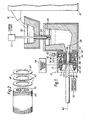
- the cylindrical mold 12 is adapted for such continuous or semi-continuous slurry casting.
- the mold 12- may be formed in a manner to be later described of any desired non-magnetic material. such as austenitic stainless steel, copper, copper alloy, aluminum,-aluminum alloy, or the like.
- the mold wall 14 may be cylindrical in nature.
- it is not limited to the formation of a cylindrical ingot cross section since it is possible to achieve a transversely or circumferentially moving magnetic field with a non-circular tubular mold arrangement not shown.
- the molten material is supplied to mold 12 through supply system 16.
- the ' molten material supply system comprises the partially shown furnace 18, trough 20, molten material flow control system or valve 22, downspout 24 and tundish 26.
- Control system 22 controls the flow of molten material from trough 20 through downspout 24 into tundish 26.
- Control system 22 also controls the height of the molten material in tundish 26.
- molten material may be supplied directly from furnace 18 into tundish 26.
- the molten material exits from tundish 26 horizontally via conduit 28 which is in direct communication with the inlet to casting mold 12.
- the solidifying casting or ingot 30 is withdrawn from mold 12 by a withdrawal mechanism 32.
- the withdrawal mechanism 32' provides the drive to the casting or ingot 30 for withdrawing it from the mold section.
- the flow rate of molten material into mold 12 is controlled by the extraction of casting or ingot 30. Any suitable conventional arrangement may be utilized for withdrawal mechanism 32.
- a cooling manifold 34 is arranged circumferentially around the mold wall 14.
- the particular manifold shown includes a first input chamber 38, a second chamber 40 connected to the first input chamber by a narrow slot 42.
- a coolant jacket sleeve 44 formed from a non-conducting material is attached to the manifold 34.
- a discharge slot 46 is defined by the gap between the coolant jacket sleeve 44 and the outer surface 48 of mold 12.
- a uniform curtain of coolant, preferably water, is provided about the outer surface 48 of the mold 12. The coolant serves to carry heat away from the molten metal via the inner wall 36 of mold 12. The coolant exits through slot 46 discharging directly against the solidifying ingot 30.
- a suitable valving arrangement 50 is provided to control the flow rate of the water or other coolant discharged in order to control the rate at which the slurry S solidifies.
- a manually operated valve 50 is shown; however, if desired this could be an electrically operated valve or any other suitable valve arrangement.
- the molten metal which is poured into the mold 12 is cooled under controlled conditions by means of the water flowing over the outer surface 48 of the mold 12 from the encompassing manifold 34.
- the rate of water flow along the mold surface 48 the rate of heat extraction from the molten metal within the mold 12 is in part controlled.
- a two pole multi-phase induction motor stator 52 is arranged surrounding the mold 12.
- the stator 52 is comprised of iron laminations 54 about which the desired windings 56 are arranged in a con- ventional manner to preferably provide a three-phase induction motor stator.
- the motor stator 52- is mounted within a motor housing M.
- any suitable means for providing power and current at different frequencies and magnitudes may be used, power and current are preferably supplied to stator 52 by'a variable frequency generator 58.
- the manifold 34 and the motor stator 52 are arranged concentrically about the axis 60 of the mold 12 and the casting 30 formed within it.
- One advantage of the two pole motor stator 52 is that there is a non-zero field across the entire cross section of the mold 12. It is, therefore, possible with this invention to solidify a casting having the desired slurry cast structure over, its full cross section.
- the magnetic stirring force vector F extends generally tangentially of the mold wall 14. This sets up within the mold cavity a rotation of the molten metal in the direction of arrow R which generates a desired shear for producing the thixotropic slurry S.
- the force vector F is also normal to the heat extraction direction and is, therefore, normal to the direction of dendrite growth.
- the stirring of the molten metal and the shear rates are functions of the magnetic induction at the periphery of the molten material.
- the mold is preferably made from a material having a high thermal conductivity in order to have the heat transfer characteristics required to effect solidification.
- Prior art molds are typically made of a thermally conductive material which tends to absorb significant portions of the induced magnetic field. It is known that this mold absorption effect increases as the frequency of the inducing current increases. As a result, prior art casting systems have been limited in the frequencies which they may utilize to operate efficiently.
- the mold of the instant invention reduces magnetic induction losses by reducing the effect of the currents induced in the mold structure itself. This is done by minimizing the path length of the induced or eddy currents in at least part, if not substantially all, of the mold thickness. By effectively eliminating the eddy current paths, the magnetic induction is allowed to pass through the mold substantially unimpeded. The stirring effect on the molten material is thereby enhanced and the process has improved efficiency while operating over a wide range of inducing current frequencies. Furthermore, the required mold heat transfer characteristics are not substantially affected.
- a completely laminated mold comprises a stack of metal or metal alloy laminations 62.
- the laminations 62 may have any desired shape.
- laminations 62 are preferably ring-shaped.
- the laminations 62 are preferably separated from each other by electrically insulating material.
- the electrically insulating material may comprise a coating of any of a variety of conventional varnishes on the upper 64 and/ or lower 66 surfaces of each lamination.
- an oxide layer not shown may be utilized on the surfaces of each lamination.
- the oxide layer may comprise a refractory oxide coating, such as an aluminum oxide coating, or any other suitable oxide coating.
- the oxide layer may be applied to the laminations in any suitable manner, such as spraying a coating on the surfaces.
- the laminations can be separated by insulating sheets or layers not shown. .
- One or more insulating sheets may be disposed between adjacent laminations.
- the insulating sheets may be made of any suitable material, i.e. asbestos, mica, fluro- carbons, phenolics, plastics such as polyvinylchloride, polycarbonates, etc.
- the stator 52 produces a magnetic field which rotates about the casting axis'60. It is known that an induced current flows in a direction opposite that of the inducing current. When the inducing current flows in a direction A, the induced current in the mold will flow in the opposite direction B.
- the electrical insulating material is oriented so as to intercept the path of the induced current. In the embodiment of Figure 2, the electrical insulating material preferably lies in a plane substantially transverse to the induced current direction. In this manner, the electrical insulating material acts as a barrier to the flow of the induced currents, thereby minimizing the path lengths of the induced currents and effectively or substantially eliminating magnetic induction losses in the mold. In the completely laminated mold of Figure 2, substantially all of the induced currents have their path lengths minimized.
- Each of the laminations 62 has a thickness A related to the penetration depth ⁇ .
- the penetration depth is the distance from the outer mold wall at which the induced field decays to 1/e.
- the thickness A should be less than about the penetration depth for any frequency which may be used. Preferably, the thickness A is less than about one-third of the penetration depth for any such frequency.
- Penetration depth ⁇ is defined by the equation:
- the mold should also exhibit heat transfer characteristics which are sufficient to effect solidification of the melt. These heat transfer characteristics influence the determination of a thickness for the electrical insulating material layers or coatings.
- the heat transfer capability of a mold is characterized by the thermal conductance of the mold. Since electrically insulating material is generally a non- conductor of heat, a mold having electrically insulating material incorporated therein generally has less thermal ccnductance than a mold not having electrically insulating material. As the amount of non-conducting material in the mold increases, the thermal conductance of the mold tends to decrease.
- the layers or coatings of electrically insulating material could have a thickness which is about the same as the lamination thickness. Preferably, the thickness of these layers or coatings is between about one mil and about 3/8".
- a tubular mold is formed by placing the laminations 62 one on top of another and joining them together.
- the laminations 62 may be welded together by placing a fine bead in several locations.
- any suitable joining means such as a bolt and nut assembly with insulating washers, may be used to join the laminations together.
- the mold may have any desired length.
- the overall wall thickness of the mold is a function of the desired electrical and heat transfer characteristics of the mold.
- the overall mold wall thickness may be up to about one inch but is preferably in the range of about 1/8" to about 3/4".
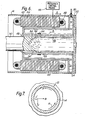
- FIG 3. An alternative embodiment of the mold 12 is shown in Figure 3.
- This embodiment comprises a laminated mold which is substantially the same as that of Figure 2 with the exception of core sleeve 68.
- the stack 70 of laminations having electrical insulating material therebetween is constructed in the same manner as the embodiment of Figure 2.
- the laminations may be joined together in any suitable fashion and have any suitable thickness.
- the electrical insulating material also has any suitable thickness. The thickness of the laminations and the electrical insulating material, being influenced by the electrical and heat transfer characteristics needed by the mold as discussed hereinbefore, are preferably in the ranges discussed in conjunction with the embodiment of Figure 2.
- Core sleeve 68 preferably comprises a thin sheet or shell of thermally conductive material.
- the sheet or shell may be affixed to the lamination stack by any suitable mechanism such as thermal shrink-fitting, thermally conductive adhesive material, etc.
- core sleeve 68 may comprise a material, such as copper, chromium, etc., plated over the inner surface of stack 70.
- Core sleeve 68 is intended to provide a clean contiguous surface which does not interfere with castability in the mold.
- Core sleeve 68 may have any desired thickness; however, it should be less than about two-thirds of the penetration depth and preferably less than about one-third of the penetration depth o for any frequency used. Penetration depth being defined by equation (1).
- the core sleeve thickness may be up to about 3/4" and is preferably in the range of about one mil to about 1/4".
- the electrical insulating material only intercepts and minimizes the flow path of some of the induced currents. Any current induced in core sleeve 68 flows substantially the entire mold length; however, the effect of such induced current on the magnetic field is reduced. While it is not fully understood why the effect on the magnetic field is reduced, it is believed that the thinness of core sleeve 68 causes it to have a higher resistance as compared to a mold having a larger cross section which in turn reduces the current flow.
- the mold of Figure 3 may have any desired length. With a mold type such as that of Figure 3, the overall magnetic induction absorption mold effect is reduced as compared to that associated with standard types of molds. Therefore, the electromagnetic stirring of the molten metal should be enhanced over conventional electromagnetic stirring processes.
- FIG 4 another alternative embodiment of a laminated mold 12 is shown.
- the mold in this embodiment is constructed from a solid tube 76 of material such as aluminum, aluminum alloy, copper, copper alloy, austenitic stainless steel, etc., having any desired length.
- the tube has an array of slits 78 extending from the outer wall 80 to within a small distance of the inner wall 82.
- slits 78 act as an air gap type of electrical insulator in minimizing the induced current path lengths.
- slits 78 may be filled with any suitable non-conducting material such as epoxy.
- the slits 78 have a thickness which is influenced by the heat transfer characteristics that the mold should exhibit.
- the slits 78 could have a thickness which is about the same as the lamination thickness. Preferably, the thickness of the slits is between about one mil and about 3/8".
- the portions 77 of mold material between the slits form the laminations.
- the portions 77 add mechanical integrity to the mold.
- These portions 77 have a thickness A which is less than about the penetration depth ⁇ for any frequency used. Penetration depth ⁇ again being defined by equation'(1).
- portions 77 have a thickness A less than about one-third of the penetration depth for any frequency used. Thickness A could be up to about 1 inch but is preferably in the range of about 1/32" to about 3/8".
- slits 78 extend from outer wall 80 to a point substantially near inner wall 82. This point is less than about two-thirds of the penetration depth from inner wall 82 and is preferably less than about one-third of the penetration depth from inner wall 82 for any frequency used.
- tube 76 has a solid continuous inner portion 83 which has a thickness less than about two-thirds of the p ene- tration depth and preferably less than about one-third of the penetration depth for any frequency used. This thickness may be up to about 3/4" but is preferably in the range of about one mil to about 1/4".
- the embodiment of Figure 5 is directed to a mold which may be used in an apparatus where the magnetic field is parallel to the casting axis 60.
- the stirring coil 75 generally has an inducing current which moves circumferentially.
- the mold comprises a stack of substantially vertical laminations 72 separated by a barrier of electrically insulating material such as that in the mold embodiments of Figures 2-4.
- The-electrically insulating material is oriented substantially transverse to the flow path of the inducing current. In this fashion, the path length of at least some induced currents will be minimized and the magnetic induction absorption substantially eliminated.
- the inner wall may have a core sleeve 74.
- Core sleeve 74 may comprise a thin sheet or shell or a thin plating of conductive material. The thicknesses of the laminations, the insulating material and the core sleeve are determined as described hereinbefore.
- the stirring force field generated by the stator-52 extend over the full solidification zone of molten metal and thixotropic metal slurry S. Otherwise, the structure of the casting will comprise regions within the field of the stator 52 having a slurry cast structure and regions outside the stator field tending to have a non-slurry cast structure.
- the solidification zone preferably comprises a sump of molten metal and slurry S within the mold 12 which extends from the mold inlet to the solidification front 84 which divides the solidified casting 30 from the slurry S.
- the solidification zone extends at least from the region of the initial onset of solidification and slurry formation in the mold cavity 86 to the solidification front 84.
- the periphery of the ingot 30 will exhibit a columnar dendritic grain structure. Such a structure is undesirable and detracts from the overall advantages of the slurry cast structure which occupies most of the ingot cross section.
- the thermal conductivity of the inlet region of any of the molds may be reduced by means of a partial mold liner 88 as shown in Figure 6 formed from an insulator such as a ceramic.
- the ceramic mold liner 88 extends from the insulating liner 90 of the mold cover 92 down into the mold cavity 86 for a distance sufficient so that the magnetic stirring force field of the two pole motor stator 52 is intercepted at least in part by the partial ceramic mold liner 88.
- the ceramic mold liner 88 is a shell which conforms to the internal shape of the mold 12 and is held to the mold wall 14.
- the mold 12 comprises a structure having a low heat conductivity inlet portion defined by the ceramic liner 88 and a high heat conductivity portion defined by the exposed portion of the mold wall 14.
- the liner 88 postpones solidification until the molten metal is in the region of the strong magnetic stirring force.
- the low heat extraction rate associated with the liner 88 generally prevents solidification in that portion of the mold 12.
- solidification 'does not'occur except towards the downstream end of the liner 88 or just thereafter.
- This region 88 or zone of low thermal conductivity thereby helps the resultant slurry cast ingot 30 to have a degenerate dendritic structure throughout its cross section even up to its outer surface.
- the initial solidification of the ingot shell may be further controlled by moderating the thermal characteristics of the casting mold as discussed in co-pending application Serial No. 258,232 to Winter et al (EP-Applic. 82103200.0) In a preferred manner, this is achieved by selectively applying a layer or band of thermally insulating material 94 on the outer wall or coolant side 48 of the mold 12 as shown in Figure 6.
- the thermal insulating layer or band 94 retards the heat transfer through mold 12 and thereby tends to slow down the solidification rate and reduce the inward growth of solidification.
- the water cooled metal casting mold wall 14 is present below the region of reduced thermal conductivity.
- the high heat transfer rates associated with this portion of the mold 12 promote ingot shell formation.
- the peripheral shell of the casting 30 could consist of degenerate dendrites in a surrounding matrix.
- the dendrites which initially form normal to the periphery-of the casting mold 12 are readily sheared off due to the metal flow resulting from the rotating magnetic field of the induction motor stator 52.
- the dendrites which are sheared off continue to be stirred to form degenerate dendrites until they are trapped by the solidifying interface.
- Degenerate dendrites can also form directly within the slurry because the rotating stirring action of the melt does not permit preferential growth of dendrites.
- the stator 52 length should preferably extend over the full length of the solidification zone.
- the stirring force field associated with the stator 52 should preferably extend over the full length and cross section of the solidification zone with a sufficient magnitude to generate the desired shear rates.
- molten metal is poured into mold cavity 86 while motor stator 52 is energized by a suitable three-phase AC current of a desired magnitude and frequency. After the molten metal is poured into the. mold cavity, it is stirred continuously by the rotating magnetic field produced by stator 52. Solidification begins from the mold wall 14. The highest shear rates are generated at the stationary mold wall 14 or at the advancing solidification front. By properly controlling the rate of solidification by any desired means as are known in the prior art, the desired thixotropic slurry S is formed in the mold cavity 86. As a solidifying shell is formed on the casting 30, the withdrawal mechanism 32 is operated to withdraw casting 30 at a desired casting rate.
- the shearing produced by the electromagnetic process and apparatus of this invention can be made equivalent to or greater than that obtainable by mechanical stirring.
- the shear rate is a maximum toward the outside of the mold. This maximum shear rate increases with increasing N. Furthermore, by using the mold of the instant invention, the magnetic induction absorption effect of the mold is reduced and the radial magnetic induction B rms at the periphery of the molten metal is increased. Consequently, the maximum shear rate increases.
- molds were constructed in accordance with several embodiments of the instant invention. Each mold was placed coaxially inside the stator of a three phase motor, and the magnetic field was measured at the center of the stator. Similar measurements for an empty stator or no mold condition and for a stator with a standard solid aluminum tube type mold having a length of about six inches, a thickness of about 1/4" , and substantially the same inner diameter as the laminated molds were done for comparison.
- a completely laminated mold was formed from aluminum rings about 1/16" thick and having an inner radius of about 1-7/8" and an outer radius of about 2-1/4". Each ring was painted with an insulating varnish about 3 mils thick and stacked on top of previously painted rings. The rings were bonded together and a tubular cylindrical mold about six inches long was constructed.
- An aluminum laminated mold was formed from an aluminum tube about six inches long having an inner radius of about 1-7/8" and an outer radius of about 2-1/4". A plurality of slits, each having a thickness about .032", were cut in the tube. The slits extended from the outer wall to within about 1/16" of the inner tube wall. The thickness of the tube sections between the slits being about 1/16".
- a copper laminated mold was constructed in the same fashion as the aluminum laminated mold.
- the copper laminated mold was formed out of a copper alloy comprising 1% Cr, balance essentially consisting of copper.
- the magnetic field at the inner mold wall or periphery of the molten metal for line frequencies of about 60, 150, 250 and 350 Hz and for stator current up to about 25 amps was measured for each mold type and for a no mold or empty stator condition.
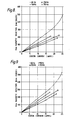
- Figure 8 shows curves representing the magnetic induction at the outside periphery of the melt or the inner-mold wall vs. stator current for frequencies of 60, 150, 250 and 350 Hz for the standard aluminum mold.
- Figures 9-11 show curves representing the magnetic induction vs. stator current for the same frequencies for the laminated aluminum, laminated copper and completely laminated molds.
- the magnetic induction vs. stator current curves for the completely laminated mold of Figure 11 are identical to the measurements for the empty stator condition.
- Figure 12 shows a comparison of the magnetic induction as a non-dimensional number B mold /B no mold vs. frequency curves for the various mold types. It can be seen from this figure that the magnetic field measured for the various laminated mold embodiments is greater than the magnetic field measured for the standard aluminum mold for all measured frequencies.
- Suitable shear rates for carrying out the process of this invention comprise from at least about 400 sec. -1 to about 1500 sec. -1 and preferably from at least about 500 sec. -1 to about 1200 sec. -1 .
- a shear rate of from about 700 sec. -1 to about 1100 sec.- l has been found desirable.
- the average cooling rates through the solidification temperature range of the molten metal in the mold should be from about 0.1°C per minute to about . 1000°C per minute and preferably from about 10°C per minute to about 500°C per minute.
- an average cooling rate of from about 40°C per minute to about 500°C per minute has been found to be suitable.
- ( ⁇ defined by equation (2)) for carrying out the process of this invention should comprise from about 1 to about 10 and preferably from about 3 to about 7.
- the parameter N (defined by equation (3)) for carrying out the process of this invention should comprise from about 1 to about 1000 and preferably from about 5 to about 200.
- the line frequency f for casting aluminum having a radius from about 1 inch to about 10 inches should be from about 3 to about 3000 hertz and preferably from about 9 to about 2000 hertz.
- the required magnetic field strength is a function of the line frequency and the melt radius and should comprise from about 50 to 1500 gauss and preferably from about 100 to about 600 gauss for casting aluminum.
- the particular parameters employed can vary from metal system to metal system in order to achieve the desired shear rates for providing the thixotropic slurry.
- Solidification zone as the term is used in this application refers to the zone of molten metal or slurry in the mold wherein solidification is taking place.
- Magnetohydrodynamic refers to the process of stirring molten metal or slurry using a moving or rotating magnetic field.
- the magnetic stirring force may be more appropriately referred to as a magnetomotive stirring force which is provided by the moving or rotating magnetic field of this invention.
- the process and apparatus of this invention is. applicable to the full range of materials as set forth in the prior casting art including, but not limited to, aluminum and its alloys, copper and its alloys, and steel and its alloys.
- the laminated mold embodiments can be used in conjunction with other types of casting systems, such as static casting systems, which utilize electromagnetic stirring of some portion of the melt during solidification.
Priority Applications (1)
| Application Number | Priority Date | Filing Date | Title |
|---|---|---|---|
| AT82106555T ATE18073T1 (de) | 1981-08-03 | 1982-07-21 | Giessform zum giessen von metallen oder legierungen und verfahren zum mischen eines metalles oder einer legierung. |
Applications Claiming Priority (2)
| Application Number | Priority Date | Filing Date | Title |
|---|---|---|---|
| US06/289,572 US4457354A (en) | 1981-08-03 | 1981-08-03 | Mold for use in metal or metal alloy casting systems |
| US289572 | 1981-08-03 |
Publications (3)
| Publication Number | Publication Date |
|---|---|
| EP0071822A1 true EP0071822A1 (de) | 1983-02-16 |
| EP0071822B1 EP0071822B1 (de) | 1986-02-19 |
| EP0071822B2 EP0071822B2 (de) | 1992-02-19 |
Family
ID=23112109
Family Applications (1)
| Application Number | Title | Priority Date | Filing Date |
|---|---|---|---|
| EP82106555A Expired - Lifetime EP0071822B2 (de) | 1981-08-03 | 1982-07-21 | Giessform zum Giessen von Metallen oder Legierungen und Verfahren zum Mischen eines Metalles oder einer Legierung |
Country Status (9)
| Country | Link |
|---|---|
| US (1) | US4457354A (de) |
| EP (1) | EP0071822B2 (de) |
| JP (1) | JPS5825853A (de) |
| AT (1) | ATE18073T1 (de) |
| AU (1) | AU8649082A (de) |
| BR (1) | BR8204453A (de) |
| CA (1) | CA1208200A (de) |
| DE (1) | DE3269169D1 (de) |
| ES (2) | ES8401349A1 (de) |
Cited By (4)
| Publication number | Priority date | Publication date | Assignee | Title |
|---|---|---|---|---|
| EP0095596A1 (de) * | 1982-06-01 | 1983-12-07 | Alumax Inc. | Verfahren und Einrichtung für das Stranggiessen von Schlicker |
| EP0120584A1 (de) * | 1983-02-23 | 1984-10-03 | Secretary of State for Trade and Industry in Her Britannic Majesty's Gov. of the U.K. of Great Britain and Northern Ireland | Giessen metallischer Materialien |
| EP2548675A1 (de) * | 2011-07-19 | 2013-01-23 | SMS Concast AG | Kokille zum Stranggiessen von metallischen Langprodukten |
| AT518123A3 (de) * | 2015-12-22 | 2021-10-15 | Presezzi Extrusion S P A | Erzeugung von Aluminiumknüppeln |
Families Citing this family (39)
| Publication number | Priority date | Publication date | Assignee | Title |
|---|---|---|---|---|
| US4709746A (en) * | 1982-06-01 | 1987-12-01 | Alumax, Inc. | Process and apparatus for continuous slurry casting |
| EP0226999B1 (de) * | 1983-03-11 | 1989-10-18 | Nissan Motor Co., Ltd. | Drosselklappensteuerungsvorrichtung für eine Verbrennungskraftmaschine |
| JPS6066840U (ja) * | 1983-10-15 | 1985-05-11 | 愛三工業株式会社 | エンジンのスロツトルバルブ制御装置 |
| JPS60128055A (ja) * | 1983-12-14 | 1985-07-08 | Nissan Motor Co Ltd | パワ−トレ−ンのスリツプ防止用制御方法 |
| JPH0650071B2 (ja) * | 1983-12-14 | 1994-06-29 | 日産自動車株式会社 | 車両の駆動力制御装置 |
| JPH0637859B2 (ja) * | 1984-10-15 | 1994-05-18 | マツダ株式会社 | エンジンのスロツトル弁制御装置 |
| JPS61226533A (ja) * | 1985-04-01 | 1986-10-08 | Nissan Motor Co Ltd | 車両用アクセル制御装置 |
| JPS6210440A (ja) * | 1985-07-05 | 1987-01-19 | Daihatsu Motor Co Ltd | エンジンのスロツトル開度制御装置 |
| FR2595597B1 (fr) * | 1986-03-13 | 1988-04-29 | Cegedur | Dispositif de reglage du niveau de la ligne de contact de la surface libre du metal avec la lingotiere dans une coulee verticale |
| USRE34906E (en) * | 1986-06-02 | 1995-04-18 | Hitachi, Ltd. | Motor-driven throttle valve assembly |
| JPH0663460B2 (ja) * | 1986-06-02 | 1994-08-22 | 株式会社日立製作所 | 電動機駆動型絞弁用の絞弁組立体 |
| JP2606824B2 (ja) * | 1986-06-06 | 1997-05-07 | 本田技研工業株式会社 | 車載内燃エンジンの絞り弁制御装置 |
| JPH0762450B2 (ja) * | 1986-06-26 | 1995-07-05 | トヨタ自動車株式会社 | 内燃機関のスロツトル弁制御装置 |
| JPH0689698B2 (ja) * | 1987-01-23 | 1994-11-09 | 株式会社日立製作所 | 内燃機関制御装置 |
| JPS63198742A (ja) * | 1987-02-12 | 1988-08-17 | Mitsubishi Electric Corp | エンジン制御装置 |
| SE460583B (sv) * | 1987-04-16 | 1989-10-30 | Asea Ab | Kokillomroerare foer omroerning av smaelta vid straenggjutning |
| JP2506831B2 (ja) * | 1987-10-28 | 1996-06-12 | 株式会社日立製作所 | 内燃機関のスロツトルアクチユエ―タ |
| CA2053990A1 (en) * | 1990-11-30 | 1992-05-31 | Gordon W. Breuker | Apparatus and process for producing shaped articles from semisolid metal preforms |
| US5178204A (en) * | 1990-12-10 | 1993-01-12 | Kelly James E | Method and apparatus for rheocasting |
| NO950843L (no) * | 1994-09-09 | 1996-03-11 | Ube Industries | Fremgangsmåte for behandling av metall i halvfast tilstand og fremgangsmåte for stöping av metallbarrer til bruk i denne fremgangsmåte |
| US6769473B1 (en) * | 1995-05-29 | 2004-08-03 | Ube Industries, Ltd. | Method of shaping semisolid metals |
| US6845809B1 (en) | 1999-02-17 | 2005-01-25 | Aemp Corporation | Apparatus for and method of producing on-demand semi-solid material for castings |
| JP3420966B2 (ja) * | 1999-03-03 | 2003-06-30 | 新日本製鐵株式会社 | 溶融金属の連続鋳造装置 |
| US6796362B2 (en) * | 2000-06-01 | 2004-09-28 | Brunswick Corporation | Apparatus for producing a metallic slurry material for use in semi-solid forming of shaped parts |
| US6402367B1 (en) | 2000-06-01 | 2002-06-11 | Aemp Corporation | Method and apparatus for magnetically stirring a thixotropic metal slurry |
| US6432160B1 (en) * | 2000-06-01 | 2002-08-13 | Aemp Corporation | Method and apparatus for making a thixotropic metal slurry |
| US6399017B1 (en) | 2000-06-01 | 2002-06-04 | Aemp Corporation | Method and apparatus for containing and ejecting a thixotropic metal slurry |
| US7024342B1 (en) | 2000-07-01 | 2006-04-04 | Mercury Marine | Thermal flow simulation for casting/molding processes |
| US6611736B1 (en) | 2000-07-01 | 2003-08-26 | Aemp Corporation | Equal order method for fluid flow simulation |
| JP3520991B1 (ja) * | 2002-09-25 | 2004-04-19 | 俊杓 洪 | 固液共存状態金属材料の製造方法 |
| JP3549055B2 (ja) * | 2002-09-25 | 2004-08-04 | 俊杓 洪 | 固液共存状態金属材料成形用ダイカスト方法、その装置、半凝固成形用ダイカスト方法およびその装置 |
| JP3549054B2 (ja) * | 2002-09-25 | 2004-08-04 | 俊杓 洪 | 固液共存状態金属材料の製造方法、その装置、半凝固金属スラリの製造方法およびその装置 |
| JP3511378B1 (ja) * | 2002-09-25 | 2004-03-29 | 俊杓 洪 | 固液共存状態金属成形用ビレットの製造方法、その装置、半溶融成形用ビレットの製造方法およびその装置 |
| US6994146B2 (en) * | 2002-11-12 | 2006-02-07 | Shaupoh Wang | Electromagnetic die casting |
| JP3630327B2 (ja) * | 2003-07-15 | 2005-03-16 | 俊杓 洪 | 固液共存状態金属スラリの製造装置 |
| CN100337772C (zh) * | 2004-11-10 | 2007-09-19 | 北京有色金属研究总院 | 一种施加复合电磁搅拌连续制备半固态金属浆料的方法 |
| TWI422820B (zh) * | 2010-04-28 | 2014-01-11 | Univ Nat Kaohsiung Applied Sci | 金屬壓合測試治具結構 |
| US10940523B2 (en) | 2018-06-01 | 2021-03-09 | The Boeing Company | Apparatus for manufacturing parts, and related methods |
| CN109822054B (zh) * | 2019-04-04 | 2024-02-20 | 佛山市稳炫智能科技有限公司 | 一种用于加工砂模具的装置及其使用方法 |
Citations (3)
| Publication number | Priority date | Publication date | Assignee | Title |
|---|---|---|---|---|
| DE1146622B (de) * | 1953-09-21 | 1963-04-04 | Ver Leichtmetallwerke Gmbh | Stranggiesskokille |
| LU78109A1 (de) * | 1977-09-09 | 1978-01-23 | ||
| GB2042385A (en) * | 1979-02-26 | 1980-09-24 | Itt | Casting thixotropic metals |
Family Cites Families (23)
| Publication number | Priority date | Publication date | Assignee | Title |
|---|---|---|---|---|
| US2861302A (en) * | 1955-09-09 | 1958-11-25 | Ver Leichtmetallwerke Gmbh | Apparatus for continuous casting |
| US2963758A (en) * | 1958-06-27 | 1960-12-13 | Crucible Steel Co America | Production of fine grained metal castings |
| US3268963A (en) * | 1964-04-08 | 1966-08-30 | Fuchs Kg Otto | Casting of metal ingots |
| US3435881A (en) * | 1967-01-03 | 1969-04-01 | Carbone Corp | Anisotropic continuous casting mold |
| US3595302A (en) * | 1967-05-11 | 1971-07-27 | Schloemann Ag | Cooling structure for continuous-casting mold |
| US3612158A (en) * | 1968-10-29 | 1971-10-12 | Concast Inc | Continuous casting mold having multiple inserts through the casting surface wall |
| US3948650A (en) * | 1972-05-31 | 1976-04-06 | Massachusetts Institute Of Technology | Composition and methods for preparing liquid-solid alloys for casting and casting methods employing the liquid-solid alloys |
| US4030534A (en) * | 1973-04-18 | 1977-06-21 | Nippon Steel Corporation | Apparatus for continuous casting using linear magnetic field for core agitation |
| US3954455A (en) * | 1973-07-17 | 1976-05-04 | Massachusetts Institute Of Technology | Liquid-solid alloy composition |
| US3936298A (en) * | 1973-07-17 | 1976-02-03 | Massachusetts Institute Of Technology | Metal composition and methods for preparing liquid-solid alloy metal composition and for casting the metal compositions |
| US3902544A (en) * | 1974-07-10 | 1975-09-02 | Massachusetts Inst Technology | Continuous process for forming an alloy containing non-dendritic primary solids |
| US4042007A (en) * | 1975-04-22 | 1977-08-16 | Republic Steel Corporation | Continuous casting of metal using electromagnetic stirring |
| US4200137A (en) * | 1975-04-22 | 1980-04-29 | Republic Steel Corporation | Process and apparatus for the continuous casting of metal using electromagnetic stirring |
| FR2310821A1 (fr) * | 1975-05-16 | 1976-12-10 | Siderurgie Fse Inst Rech | Lingotiere de coulee a parois minces |
| FR2315344A1 (fr) * | 1975-06-27 | 1977-01-21 | Siderurgie Fse Inst Rech | Lingotiere de coulee continue electrorotative |
| FR2324395A1 (fr) * | 1975-09-17 | 1977-04-15 | Siderurgie Fse Inst Rech | Lingotiere a inducteurs incorpores |
| FR2324397B1 (fr) * | 1975-09-19 | 1979-06-15 | Siderurgie Fse Inst Rech | Procede et dispositif pour le brassage electromagnetique des produits de coulee continue |
| FR2338755A1 (fr) * | 1976-01-20 | 1977-08-19 | Siderurgie Fse Inst Rech | Procede de coulee continue centrifuge electromagnetique de produits metalliques |
| US3995678A (en) * | 1976-02-20 | 1976-12-07 | Republic Steel Corporation | Induction stirring in continuous casting |
| NL7700977A (nl) * | 1976-02-24 | 1977-08-26 | Alusuisse | Werkwijze en inrichting voor het continu gieten van een metaalsmelt in gietvormen. |
| FR2382295A1 (fr) * | 1977-03-03 | 1978-09-29 | Usinor | Lingotiere de coulee continue munie d'un dispositif de brassage electro-magnetique |
| US4229210A (en) * | 1977-12-12 | 1980-10-21 | Olin Corporation | Method for the preparation of thixotropic slurries |
| JPS5626661A (en) * | 1979-08-07 | 1981-03-14 | Nippon Steel Corp | Molten metal cooling mold of less electromagnetic force transmission loss |
-
1981
- 1981-08-03 US US06/289,572 patent/US4457354A/en not_active Expired - Lifetime
-
1982
- 1982-07-21 EP EP82106555A patent/EP0071822B2/de not_active Expired - Lifetime
- 1982-07-21 DE DE8282106555T patent/DE3269169D1/de not_active Expired
- 1982-07-21 AT AT82106555T patent/ATE18073T1/de not_active IP Right Cessation
- 1982-07-29 CA CA000408440A patent/CA1208200A/en not_active Expired
- 1982-07-29 BR BR8204453A patent/BR8204453A/pt unknown
- 1982-07-29 AU AU86490/82A patent/AU8649082A/en not_active Abandoned
- 1982-08-02 ES ES514649A patent/ES8401349A1/es not_active Expired
- 1982-08-03 JP JP57134810A patent/JPS5825853A/ja active Granted
-
1983
- 1983-09-01 ES ES525303A patent/ES8500103A1/es not_active Expired
Patent Citations (3)
| Publication number | Priority date | Publication date | Assignee | Title |
|---|---|---|---|---|
| DE1146622B (de) * | 1953-09-21 | 1963-04-04 | Ver Leichtmetallwerke Gmbh | Stranggiesskokille |
| LU78109A1 (de) * | 1977-09-09 | 1978-01-23 | ||
| GB2042385A (en) * | 1979-02-26 | 1980-09-24 | Itt | Casting thixotropic metals |
Cited By (8)
| Publication number | Priority date | Publication date | Assignee | Title |
|---|---|---|---|---|
| EP0095596A1 (de) * | 1982-06-01 | 1983-12-07 | Alumax Inc. | Verfahren und Einrichtung für das Stranggiessen von Schlicker |
| EP0120584A1 (de) * | 1983-02-23 | 1984-10-03 | Secretary of State for Trade and Industry in Her Britannic Majesty's Gov. of the U.K. of Great Britain and Northern Ireland | Giessen metallischer Materialien |
| US4621676A (en) * | 1983-02-23 | 1986-11-11 | The Secretary Of State For Trade And Industry In Her Britanic Majesty's Government Of The United Kingdom Of Great Britain And Northern Ireland | Casting of metallic materials |
| AU567363B2 (en) * | 1983-02-23 | 1987-11-19 | Secretary Of State For Trade And Industry In Her Britannic Majesty's Government Of The United Kingdom Of Great Britain And Northern Ireland, The | Casting of metallic materials |
| EP2548675A1 (de) * | 2011-07-19 | 2013-01-23 | SMS Concast AG | Kokille zum Stranggiessen von metallischen Langprodukten |
| WO2013010663A1 (de) * | 2011-07-19 | 2013-01-24 | Sms Concast Ag | Kokille zum stranggiessen von metallischen langprodukten |
| AT518123A3 (de) * | 2015-12-22 | 2021-10-15 | Presezzi Extrusion S P A | Erzeugung von Aluminiumknüppeln |
| AT518123B1 (de) * | 2015-12-22 | 2022-07-15 | Presezzi Extrusion S P A | Erzeugung von Aluminiumknüppeln |
Also Published As
| Publication number | Publication date |
|---|---|
| ES525303A0 (es) | 1984-10-01 |
| DE3269169D1 (en) | 1986-03-27 |
| EP0071822B2 (de) | 1992-02-19 |
| ES514649A0 (es) | 1983-12-01 |
| ATE18073T1 (de) | 1986-03-15 |
| JPS5825853A (ja) | 1983-02-16 |
| ES8500103A1 (es) | 1984-10-01 |
| JPS637867B2 (de) | 1988-02-18 |
| EP0071822B1 (de) | 1986-02-19 |
| ES8401349A1 (es) | 1983-12-01 |
| AU8649082A (en) | 1983-02-10 |
| BR8204453A (pt) | 1983-07-19 |
| CA1208200A (en) | 1986-07-22 |
| US4457354A (en) | 1984-07-03 |
Similar Documents
| Publication | Publication Date | Title |
|---|---|---|
| EP0071822B1 (de) | Giessform zum Giessen von Metallen oder Legierungen und Verfahren zum Mischen eines Metalles oder einer Legierung | |
| US4434837A (en) | Process and apparatus for making thixotropic metal slurries | |
| US4465118A (en) | Process and apparatus having improved efficiency for producing a semi-solid slurry | |
| CA1176819A (en) | Process and apparatus for making thixotropic metal slurries | |
| US4457355A (en) | Apparatus and a method for making thixotropic metal slurries | |
| US4482012A (en) | Process and apparatus for continuous slurry casting | |
| US2963758A (en) | Production of fine grained metal castings | |
| CA1176820A (en) | Apparatus for making thixotropic metal slurries | |
| EP0063757B1 (de) | Verfahren und Einrichtung für das Giessen von Metallen und Legierungen | |
| US4709746A (en) | Process and apparatus for continuous slurry casting | |
| US4294304A (en) | Electromagnetic centrifuging inductor for rotating a molten metal about its casting axis | |
| CN103600045B (zh) | 电磁激振复合机械搅拌的金属连铸工艺及金属连铸装置 | |
| US4607682A (en) | Mold for use in metal or metal alloy casting systems | |
| US20080164004A1 (en) | Method and system of electromagnetic stirring for continuous casting of medium and high carbon steels | |
| EP0543290A2 (de) | Verfahren zum Giessen von Ingots mit durch Verwendung eines magnetischen Feldes verringerter Makroseigerung, Vorrichtung und Ingot | |
| JPH0255650A (ja) | 連続鋳造によるチキソトロピー性の金属製品の製法 | |
| EP0093248A2 (de) | Verfahren und Vorrichtung zur Herstellung von thixotropen Gefügen der Legierungen durch Wärmebehandlung | |
| JPS5947621B2 (ja) | 連続鋳造法 | |
| US4103730A (en) | Process for electromagnetic stirring | |
| JPH06315740A (ja) | マグネチックスターラによる半凝固金属スラリの製造方法 | |
| KR950002967B1 (ko) | 용강의 연속 주조 장치 및 그 방법 | |
| CN108526424A (zh) | 一种双频电磁搅拌的磁场发生器 | |
| JPH081281A (ja) | 半凝固金属材料の製造方法及びその製造装置 | |
| CA2041778A1 (en) | Method and apparatus for rheocasting | |
| CN101214533A (zh) | 空心铜及其铜合金管的电磁水平连续铸造装置 |
Legal Events
| Date | Code | Title | Description |
|---|---|---|---|
| PUAI | Public reference made under article 153(3) epc to a published international application that has entered the european phase |
Free format text: ORIGINAL CODE: 0009012 |
|
| 17P | Request for examination filed |
Effective date: 19820830 |
|
| AK | Designated contracting states |
Designated state(s): AT BE CH DE FR GB IT LI NL SE |
|
| GRAA | (expected) grant |
Free format text: ORIGINAL CODE: 0009210 |
|
| AK | Designated contracting states |
Designated state(s): AT BE CH DE FR GB IT LI NL SE |
|
| PG25 | Lapsed in a contracting state [announced via postgrant information from national office to epo] |
Ref country code: NL Effective date: 19860219 Ref country code: IT Free format text: LAPSE BECAUSE OF FAILURE TO SUBMIT A TRANSLATION OF THE DESCRIPTION OR TO PAY THE FEE WITHIN THE PRESCRIBED TIME-LIMIT;WARNING: LAPSES OF ITALIAN PATENTS WITH EFFECTIVE DATE BEFORE 2007 MAY HAVE OCCURRED AT ANY TIME BEFORE 2007. THE CORRECT EFFECTIVE DATE MAY BE DIFFERENT FROM THE ONE RECORDED. Effective date: 19860219 Ref country code: BE Effective date: 19860219 Ref country code: AT Effective date: 19860219 |
|
| REF | Corresponds to: |
Ref document number: 18073 Country of ref document: AT Date of ref document: 19860315 Kind code of ref document: T |
|
| REF | Corresponds to: |
Ref document number: 3269169 Country of ref document: DE Date of ref document: 19860327 |
|
| RAP2 | Party data changed (patent owner data changed or rights of a patent transferred) |
Owner name: ALUMAX, INC. |
|
| ET | Fr: translation filed | ||
| NLV1 | Nl: lapsed or annulled due to failure to fulfill the requirements of art. 29p and 29m of the patents act | ||
| PG25 | Lapsed in a contracting state [announced via postgrant information from national office to epo] |
Ref country code: SE Effective date: 19860722 |
|
| PG25 | Lapsed in a contracting state [announced via postgrant information from national office to epo] |
Ref country code: LI Effective date: 19860731 Ref country code: CH Effective date: 19860731 |
|
| PLBI | Opposition filed |
Free format text: ORIGINAL CODE: 0009260 |
|
| 26 | Opposition filed |
Opponent name: ASEA AKTIEBOLAG Effective date: 19861118 |
|
| REG | Reference to a national code |
Ref country code: CH Ref legal event code: PL |
|
| RAP2 | Party data changed (patent owner data changed or rights of a patent transferred) |
Owner name: ALUMAX, INC. |
|
| PUAH | Patent maintained in amended form |
Free format text: ORIGINAL CODE: 0009272 |
|
| STAA | Information on the status of an ep patent application or granted ep patent |
Free format text: STATUS: PATENT MAINTAINED AS AMENDED |
|
| RAP2 | Party data changed (patent owner data changed or rights of a patent transferred) |
Owner name: ALUMAX, INC. |
|
| 27A | Patent maintained in amended form |
Effective date: 19920219 |
|
| AK | Designated contracting states |
Kind code of ref document: B2 Designated state(s): AT BE CH DE FR GB IT LI NL SE |
|
| ET3 | Fr: translation filed ** decision concerning opposition | ||
| EUG | Se: european patent has lapsed |
Ref document number: 82106555.4 Effective date: 19870609 |
|
| PGFP | Annual fee paid to national office [announced via postgrant information from national office to epo] |
Ref country code: FR Payment date: 20010712 Year of fee payment: 20 |
|
| PGFP | Annual fee paid to national office [announced via postgrant information from national office to epo] |
Ref country code: DE Payment date: 20010716 Year of fee payment: 20 |
|
| PGFP | Annual fee paid to national office [announced via postgrant information from national office to epo] |
Ref country code: GB Payment date: 20010718 Year of fee payment: 20 |
|
| REG | Reference to a national code |
Ref country code: GB Ref legal event code: IF02 |
|
| PG25 | Lapsed in a contracting state [announced via postgrant information from national office to epo] |
Ref country code: GB Free format text: LAPSE BECAUSE OF EXPIRATION OF PROTECTION Effective date: 20020720 |
|
| REG | Reference to a national code |
Ref country code: GB Ref legal event code: PE20 Effective date: 20020720 |