EP0071798B1 - Schallgedämpfte automatische Handfeuerwaffe - Google Patents
Schallgedämpfte automatische Handfeuerwaffe Download PDFInfo
- Publication number
- EP0071798B1 EP0071798B1 EP82106363A EP82106363A EP0071798B1 EP 0071798 B1 EP0071798 B1 EP 0071798B1 EP 82106363 A EP82106363 A EP 82106363A EP 82106363 A EP82106363 A EP 82106363A EP 0071798 B1 EP0071798 B1 EP 0071798B1
- Authority
- EP
- European Patent Office
- Prior art keywords
- locking lever
- trigger
- pawl
- breech
- fire
- Prior art date
- Legal status (The legal status is an assumption and is not a legal conclusion. Google has not performed a legal analysis and makes no representation as to the accuracy of the status listed.)
- Expired
Links
- 238000010304 firing Methods 0.000 claims abstract description 13
- 230000001154 acute effect Effects 0.000 claims description 3
- 230000003584 silencer Effects 0.000 claims description 2
- 230000030279 gene silencing Effects 0.000 abstract 1
- 230000001629 suppression Effects 0.000 description 5
- 230000006835 compression Effects 0.000 description 2
- 238000007906 compression Methods 0.000 description 2
- 230000007257 malfunction Effects 0.000 description 2
- 238000000034 method Methods 0.000 description 2
- 206010043268 Tension Diseases 0.000 description 1
- 239000012141 concentrate Substances 0.000 description 1
- 230000005764 inhibitory process Effects 0.000 description 1
- 239000003380 propellant Substances 0.000 description 1
- 230000007704 transition Effects 0.000 description 1
Images
Classifications
-
- F—MECHANICAL ENGINEERING; LIGHTING; HEATING; WEAPONS; BLASTING
- F41—WEAPONS
- F41A—FUNCTIONAL FEATURES OR DETAILS COMMON TO BOTH SMALLARMS AND ORDNANCE, e.g. CANNONS; MOUNTINGS FOR SMALLARMS OR ORDNANCE
- F41A19/00—Firing or trigger mechanisms; Cocking mechanisms
- F41A19/06—Mechanical firing mechanisms, e.g. counterrecoil firing, recoil actuated firing mechanisms
- F41A19/25—Mechanical firing mechanisms, e.g. counterrecoil firing, recoil actuated firing mechanisms having only slidably-mounted striker elements, i.e. percussion or firing pins
- F41A19/27—Mechanical firing mechanisms, e.g. counterrecoil firing, recoil actuated firing mechanisms having only slidably-mounted striker elements, i.e. percussion or firing pins the percussion or firing pin being movable relative to the breech-block
- F41A19/29—Mechanical firing mechanisms, e.g. counterrecoil firing, recoil actuated firing mechanisms having only slidably-mounted striker elements, i.e. percussion or firing pins the percussion or firing pin being movable relative to the breech-block propelled by a spring under tension
- F41A19/30—Mechanical firing mechanisms, e.g. counterrecoil firing, recoil actuated firing mechanisms having only slidably-mounted striker elements, i.e. percussion or firing pins the percussion or firing pin being movable relative to the breech-block propelled by a spring under tension in bolt-action guns
- F41A19/33—Arrangements for the selection of automatic or semi-automatic fire
-
- F—MECHANICAL ENGINEERING; LIGHTING; HEATING; WEAPONS; BLASTING
- F41—WEAPONS
- F41A—FUNCTIONAL FEATURES OR DETAILS COMMON TO BOTH SMALLARMS AND ORDNANCE, e.g. CANNONS; MOUNTINGS FOR SMALLARMS OR ORDNANCE
- F41A3/00—Breech mechanisms, e.g. locks
- F41A3/12—Bolt action, i.e. the main breech opening movement being parallel to the barrel axis
- F41A3/36—Semi-rigid bolt locks, i.e. having locking elements movably mounted on the bolt or on the barrel or breech housing
- F41A3/38—Semi-rigid bolt locks, i.e. having locking elements movably mounted on the bolt or on the barrel or breech housing having rocking locking elements, e.g. pivoting levers or vanes
Definitions
- the invention relates to a silenced automatic handgun with a muffler for firing projectiles with a muzzle velocity in the subsonic area, with an optionally effective locking lever which is pivotable about an axis arranged transversely to the barrel axis and locks the closed breech during firing.
- DE-B-1 095 166 discloses a weapon of the type described at the outset, but without a muzzle silencer and without the possibility of firing projectiles with a muzzle velocity in the subsonic area.
- the locking lever of the known weapon is supported in the locked position with its end facing away from the breech on a part fixed to the housing and is intended to make it possible to use special ammunition with a stronger propellant charge than is permissible for the safe functioning of the automatic charging process.
- the locking lever is either brought into its active position or out of action by the shooter by means of an actuating slide independent of the trigger system. If after firing a shot in which the locking lever was in the active position, the weapon should be reloaded or reloaded, the shooter must first deactivate the locking lever by actuating the actuating element mentioned and then, if necessary, bring it back into the active position.
- the invention is therefore based on the object to provide a weapon of the type described, in which the shooter does not have to bring the locking lever before and after firing each shot by means of a special handle into active position or out of active position.
- a ratchet is connected to a trigger of a weapon of the type described above, which pivots the locking lever against the force of a spring into the locking position when pulling the trigger, and that the locking lever of the spring when the trigger system is not actuated is kept out of engagement with the closure.
- the weapon can be used both for single shots with suppression of the breech noise as well as for single shots without suppression of the breech noise or as an automatic weapon for burst or continuous fire, here also without suppression of the breech noise. If the weapon is set in such a way that the locking lever can be made effective, the locking lever is out of action due to the spring acting on it when the trigger is not actuated, and the weapon can be loaded in this position. When pulling the trigger, the locking lever is pivoted into the locking position by the pawl. If the trigger is released after firing a shot, the locking lever automatically swings back under the action of the spring loading it and releases the breech, whereby the shooter can load the weapon in the usual way and make it ready to fire again.
- an automatic firearm which has a lever which can be brought into a locked position in which it locks the breech.
- the purpose of this lever in the known weapon is that a movement of the breech when the weapon is not in use, for example during transport, as a result of hard impacts should be avoided, because such impacts pose the risk that as a result of such undesired movements of the breech inhibitions of the weapon occur.
- Said locking lever is coupled to a safety lever which allows the types of fire burst fire and individual fire to be switched on and also has a safe position.
- the locking lever is only in the active position when the locking lever is brought into a position “locking” in addition to the positions just mentioned. In the case of the weapon described in the exemplary embodiment of the cited print, it is therefore not possible to fire individual fires with the locking lever in the operative position.
- CH-A-440045 discloses a device for preventing rebounding of the breech parts of an automatic firearm with the trigger a locking lever held by a spring when the trigger is not actuated out of engagement with the closure is brought into engagement with the closure when the trigger is actuated.
- the locking lever is brought out of the operative position so that the automatic loading process can take place as with conventional self-loading weapons.
- the breech comes back to its front position after its return movement, the trigger being still in the pulled state due to the speed of the movement of the breech, the locking lever comes into engagement with the trigger again and thus prevents the trigger from rebounding.
- the known device should make it unnecessary to provide so-called reference masses to prevent the bouncing back of the closure.
- the pawl can be arranged at any constructive point of the trigger system, for example on a trigger rod or the like.
- the pawl is pivotally mounted on the trigger itself. When the trigger is pulled, it engages the locking lever and pivots it into the locked position, which is reached shortly before the shot breaks. If the shooter then lets go of the trigger, the lock is automatically unlocked.
- Automatic handguns are usually provided with a safety shaft with which the types of fire can be set, such as individual fire, continuous fire, burst of fire or safe, with the latter being unable to fire a shot.
- a shot in which the shutter noise is suppressed by locking the shutter, is of course only possible with single fire and not with the type of burst or continuous fire. In all types of fire, however, the triggering of the shot is effected by the trigger.
- the pawl protrudes with one end into the area of the safety shaft, which is provided with a projection which disengages the pawl from the locking lever in the fire mode positions of continuous fire and burst of fire.
- the safety shaft could have two types of fire positions for individual fires and, in one of these positions, also disengage the pawl from the locking lever.
- the weapon would then be designed in such a way that it has two different types of fire, single fire, namely one with a bolt lock and one without a bolt lock, whereby in the type of fire without bolt lock the weapon can be used as a conventional automatic handgun and only in the type of fire with bolt lock the increased noise reduction by suppression the shutter sound is achieved.
- the closure is provided with a cutout into which the locking lever engages in the locking position, wherein it rests on a surface arranged transversely to the closure movement path. This surface is preferably arranged approximately tangentially to the axis of the locking lever.
- the engagement surface of the locking lever located in the locking position includes an acute wedge angle with the surface of the recess of the closure, the wedge tip of which points in the opposite direction to the direction in which the engagement surface moves during the transition into the locking position. This ensures that there is no play and locking of the closure.
- a spring element is switched into the path of the force flow from the trigger to the engagement surface of the locking lever.
- the arrangement would have to be manufactured with extremely high precision, because this is the only way to achieve the desired freedom from play.
- a spring element is switched on in the power flow, this spring element compensates for small inaccuracies and tolerances and still ensures that the lock is locked without play.
- the spring element can be switched on, for example, between the pawl and the locking lever.
- the pawl can engage an intermediate lever mounted on the locking lever, which in turn is supported by a spring against the locking lever.
- the pawl itself can be designed as a leaf spring that deforms elastically.
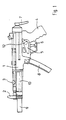
- the weapon shown in Fig. 1 comprises a housing 1 with a tube covered by a hand guard 10, a sighting device 2 and a loading lever 3, which allows a manual loading of the weapon.
- the weapon also comprises a pistol grip 4 with a trigger box 5 and a trigger 6 attached to it. It is provided with an extendable shoulder rest 7.
- the ammunition is housed in a rod magazine 8.
- a muzzle muffler 9 connects to the barrel mouth.
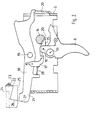
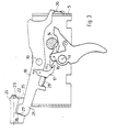
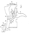
- the trigger 6 is pivotally mounted about an axis 11 in the trigger box 5. Parallel to the axis 11, a safety shaft 14 is rotatably mounted in the trigger box 5, which can be pivoted into its various positions via an external safety lever 12, of which FIGS. 2 and 3 show the position which is characteristic of the type of fire "individual fire with locked closure, whereas FIG 4 shows a position in which the lock is not locked.
- a pawl 15 is pivotally mounted about an axis 16, which is loaded counterclockwise by a spring, not shown.
- the pawl in the position of the securing shaft 14 shown in FIGS. 2 and 3 is moved from the position according to FIG. 2 to the position according to FIG Arm 17 of a locking lever 18 extending in the longitudinal direction of the weapon comes into contact, which is pivotally mounted in the trigger box 5 about an axis 19 directed transversely to the barrel axis and thereby brings the locking lever 18 into a position in which it places the breech 22 and thereby locks it .
- the locking lever 18 is designed as a two-armed lever, on which in the region of its rear end a helical compression spring 20 engages, which is supported against the trigger box 5 and loads it in the counterclockwise direction and strives, its opposite end 21 from the movement path of the lock 22, which is the firing pin 23 contains to pivot out.
- a cutout 25 is incorporated, which has an abutment surface 26 running approximately transversely to the axis 24 for an end engagement surface 27 at the front end 21 of the locking lever 18.
- the engagement surface 27 on the locking lever 18 forms a very acute angle with the contact surface 26, the tip of which points away from the axis 24.
- the engagement surface 27 can also be curved and, for example, in the form of a cylindrical jacket surface, the central axis of which is displaced somewhat downward in the direction of the trigger 6 with respect to the axis 19 of the locking lever 18.
- the engagement surface 27 can also be a flat surface. Due to the wedge angle between the two surfaces 26 and 27, a play-free contact and thus a play-free locking of the closure carrier 25 is achieved.
- a spring element is provided and switched on in the power flow between the trigger 6 and the engagement surface 27.
- This spring element is realized, for example, in that the arm 17 is pivotably mounted on the locking lever 18 and is biased towards the pawl 15 by a compression spring 28 which is supported against the locking lever 18. As a result, the locking lever 18 is not driven positively, but non-positively.
- the securing shaft 14 is provided in all its positions, which correspond to types of fire without a locking lock, with a shoulder or a surface 29 which pivots the pawl 15 in a clockwise direction thereby disengaging the arm 17.
- the spring 20 then holds the front end 21 of the locking lever 18 outside the movement path of the closure carrier 22nd
- the weapon described can be so as the known use sc h allgedämpfte submachine gun, it gives the user but also the ability to deliver single shots in non-automatic operation in a way in which even the shutter sound is totally suppressed, but the weapon either by mere Swiveling the safety shaft as well as the known submachine gun can be used with full firepower.
Landscapes
- Engineering & Computer Science (AREA)
- General Engineering & Computer Science (AREA)
- Toys (AREA)
- Developing Agents For Electrophotography (AREA)
- Lock And Its Accessories (AREA)
- Table Devices Or Equipment (AREA)
- Vending Machines For Individual Products (AREA)
- Washing And Drying Of Tableware (AREA)
- Load-Engaging Elements For Cranes (AREA)
- Operating, Guiding And Securing Of Roll- Type Closing Members (AREA)
Description
- Die Erfindung betrifft eine geräuschgedämpfte automatische Handfeuerwaffe mit einem Mündungsschalldämpfer zum Verschießen von Geschossen mit einer Mündungsgeschwindigkeit im Unterschallbereich, mit einem wahlweise wirksamen Sperrhebel, der um eine zur Laufachse quer angeordnete Achse schwenkbar ist und den geschlossenen Verschluß während der Schußabgabe verriegelt. Eine Waffe der eingangs geschilderten Art, jedoch ohne Mündungsschalldämpfer und ohne die Möglichkeit, Geschosse mit einer Mündungsgeschwindigkeit im Unterschallbereich zu verschiessen, ist durch die DE-B-1 095 166 bekannt. Der Sperrhebel der bekannten Waffe stützt sich in der Sperrstellung mit seinem dem Verschluß abgewandten Ende an einem gehäusefesten Teil ab und soll es dadurch ermöglichen, Sondermunition mit einer stärkeren Treibladung, als sie für die sichere Funktion des automatisch ablaufenden Ladevorganges zulässig ist, zu verwenden. Der Sperrhebel wird durch einen vom Abzugssystem unabhängigen Betätigungsschieber vom Schützen wahlweise in seine Wirkstellung oder außer Wirkung gebracht. Soll nach Abgabe eines Schusses, bei dem der Sperrhebel in Wirkstellung war, die Waffe erneut geladen oder durchgeladen werden, so muß der Schütze vorher den Sperrhebel durch Betätigen des genannten Betätigungselementes außer Wirkung bringen und anschließend ggf. erneut in Wirkstellung bringen.
- Würde man eine bekannte, mit einem Mündungsschalldämpfer versehene automatische Waffe (Maschinenpistole MP 5 SD) mit einem Sperrhebel der eingangs geschilderten Art versehen, so wäre zwar bei Abgabe eines Schusses sowohl der Mündungsknall als auch das Verschlußgeräusch stark verringert, so daß man daran denken könnte, eine derartige Waffe bei Einsatzfällen zu verwenden, bei denen auch das nicht sehr laute Geräusch des Verschlusses vermieden werden muß, weil es die Anwesenheit und den Standort des Schützen verrät. Bei einer derartigen Waffe mit einem manuell zu betätigenden Sperrhebel kann es jedoch leicht vorkommen, daß bedingt durch die Aufregung während der entscheidenden Phase einer Aktion das Einrücken des Sperrhebels vergessen wird. Auch ist bei einer derartigen Waffe für das nach dem Abgeben eines Schusses erforderliche Durchladen ein manuelles Entriegeln des Sperrhebel erforderlich.
- Der Erfindung liegt daher die Aufgabe zugrunde, eine Waffe der eingangs geschilderten Art zu schaffen, bei der der Schütze nicht den Sperrhebel vor und nach Abgabe eines jeden Schusses mittels einer besonderen Handhabe in Wirkstellung bzw. außer Wirkstellung bringen muß.
- Bei der Erfindung ist vorgesehen, daß bei einer Waffe der eingangs geschilderten Art mit dem Abzugssystem eine Klinke verbunden ist, die beim Durchziehen des Abzugs den Sperrhebel entgegen der Kraft einer Feder in die Verriegelungsstellung schwenkt, und daß der Sperrhebel bei nicht betätigtem Abzugssystem von der Feder außer Eingriff mit dem Verschluß gehalten ist.
- Die Waffe kann sowohl für Einzelschüsse mit Unterdrückung des Verschlußgeräusches als auch für Einzelschüsse ohne Unterdrückung des Verschlußgeräusches oder als automatische Waffe für Feuerstoß oder Dauerfeuer, hier ebenfalls ohne Unterdrückung des Verschlußgeräusches verwendet werden. Ist die Waffe so eingestellt, daß der Sperrhebel wirksam gemacht werden kann, so befindet sich bei nicht betätigtem Abzug der Sperrhebel infolge der ihn beaufschlagenden Feder außer Wirkstellung und in dieser Stellung kann die Waffe durchgeladen werden. Beim Durchziehen des Abzugs wird der Sperrhebel durch die Klinke in die Verriegelungsstellung geschwenkt. Wird der Abzug nach der Abgabe eines Schusses losgelassen, dann schwenkt der Sperrhebel unter der Wirkung der ihn belastenden Feder selbsttätig zurück und gibt den Verschluß frei, wodurch der Schütze die Waffe in üblicher Weise durchladen und wieder schußbereit machen kann. Auf diese Weise wird eine erhöhte Sicherheit gegen Fehlfunktionen und Fehlbedienungen erzielt, weil der Schütze sich vollständig auf seine Aktion konzentrieren kann und die Waffe unverändert gegenüber jeder anderen Waffe bedient werden kann. Dies ist bei Sondereinsätzen und Kommandounternehmen, bei denen die Beteiligten ohnedies unter hoher nervlicher Anspannung stehen, von besonderer Bedeutung.
- Durch die DE-A-14 28 772 ist eine automatische Feuerwaffe bekannt, die einen Hebel aufweist, der in eine Sperrstellung gebracht werden kann, in der er den Verschluß arretiert. Der Zweck dieses Hebels besteht bei der bekannten Waffe darin, daß eine Bewegung des Verschlusses dann, wenn die Waffe nicht benutzt wird, beispielsweise beim Transport, infolge von harten Stößen vermieden werden soll, weil durch derartige Stöße die Gefahr besteht, daß infolge derartiger ungewünschter Bewegungen des' Verschlusses Hemmungen der Waffe auftreten. Der genannte Sperrhebel ist mit einem Sicherungshebel, der die Feuerarten Feuerstoß und Einzelfeuer einzuschalten gestattet und außerdem eine Stellung sicher aufweist, gekoppelt. Dabei ist der Sperrhebel lediglich dann in Wirkstellung, wenn der Sicherungshebel in eine zusätzlich zu den soeben genannten Stellungen vorhandene Stellung « Arretierung gebracht ist. Bei dem im Ausführungsbeispiel der genannten Durckschrift beschriebenen Waffe ist daher nicht möglich, Einzelfeuer mit in Wirkstellung befindlichem Sperrhebel abzugeben.
- Durch die CH-A-440045 ist eine Vorrichtung zum Verhindern des Rückpralls der Verschlußteile einer automatischen Feuerwaffe bekannt, bei der mit dem Abzug ein von einer Feder bei nicht betätigtem Abzug außer Eingriff mit dem Verschluß gehaltener Sperrhebel beim Betätigen des Abzuges in Eingriff mit dem Verschluß gebracht wird. Der Sperrhebel wird jedoch beim Abschlagen des Hammers von diesem außer Wirkstellung gebracht, so daß der automatische Ladevorgang wie bei herkömmlichen Selbstladewaffen ablaufen kann. Sobald der Verschluß nach seiner Rücklaufbewegung wieder in seine vordere Stellung gelangt, wobei sich infolge der Schnelligkeit des Bewegungsablaufes des Verschlusses der Abzug noch im durchgezogenen Zustand befindet, gelangt der Sperrhebel wieder in Eingriff mit dem Abzug und verhindert somit ein Zurückprallen des Abzugs. Durch die bekannte Vorrichtung soll es überflüssig werden, zum Verhindern des Rückpralls des Verschlusses sog. Nachschlagmassen vorzusehen.
- Die Klinke kann an beliebiger konstruktiv zweckmäßiger Stelle des Abzugssystemes angeordnet sein, beispielsweise an einer Abzugsstange oder dgl. Bevorzugt ist die Klinke am Abzug selbst schwenkbar gelagert. Bei Durchziehen des Abzuges greift sie an dem Sperrhebel an und verschwenkt diesen in die Sperrstellung, die erreicht wird, kurz bevor der Schuss bricht. Läßt danach der Schütze den Abzug wieder los dann ist damit der Verschluß selbsttätig wieder entsperrt.
- Automatische Handfeuerwaffen sind üblicherweise mit einer Sicherungswelle versehen, mit der die Feuerarten einstellbar sind, wie beispielsweise Einzelfeuer, Dauerfeuer, Feuerstoß oder Sicher, wobei bei letzterer eine Schußabgabe nicht möglich ist. Eine Schußabgabe, bei der auch das Verschlußgeräusch durch Verriegelung des Verschlusses unterdrückt ist, ist selbstverständlich nur bei Einzelfeuer und nicht bei der Feuerart Feuerstoß oder Dauerfeuer möglich. Bei sämtlichen Feuerarten wird jedoch die Schußauslösung durch den Abzug bewirkt.
- Bei einer bevorzugten Ausführungsform der Erfindung ragt daher die Klinke mit einem Ende in den Bereich der Sicherungswelle, die mit einem Ansatz versehen ist, der die Klinke in den Feuerartstellungen Dauerfeuer und Feuerstoß außer Eingriff mit dem Sperrhebel bringt. Auf diese Weise ist gewährleistet, daß die Waffe bei der Umstellung auf die Feuerart Dauerfeuer und Feuerstoß selbsttätig ihre Funktion als automatische Feuerwaffe zurückerhält, ohne daß der Schütze irgendeine zusätzliche weitere Manipulation vornehmen muß. Dabei könnte die Sicherungswelle zwei Feuerartenstellungen für Einzelfeuer aufweisen und in einer dieser Stellungen ebenfalls die Klinke mit dem Sperrhebel außer Eingriff bringen. Die Waffe wäre dann derart ausgebildet, daß sie zwei verschiedene Feuerarten Einzelfeuer aufweist, nämlich eine mit Verschlußsperrung und eine ohne Verschlußsperrung, wobei in der Feuerart ohne Verschlußsperrung die Waffe als übliche automatische Handfeuerwaffe einsetzbar ist und nur in der Feuerart mit Verschlußsperrung die erhöhte Geräuschdämpfung durch Unterdrückung des Verschlußgeräusches erzielt wird.
- Der Eingriff des Sperrhebels in die Verschlußbahn kann unterschiedlich verwirklicht sein. Bei einer bevorzugten Ausführungsform der Erfindung ist der Verschluß mit einer Ausfräsung versehen, in die der Sperrhebel in der Sperrstellung eingreift, wobei er an einer zur Verschlußbewegungsbahn quer angeordneten Fläche anliegt. Dabei ist bevorzugt diese Fläche etwa tangential zur Achse des Sperrhebels angeordnet.
- Wesentlich für die Unterdrückung des Verschlußgeräusches ist, daß die Sperrung des Verschlusses spielfrei erfolgt. Dies kann beispielsweise dadurch erzielt sein, daß zwischen Verschluß und Sperrhebel ein elastischer, in der Eingriffsstellung vorgespannter Puffer vorgesehen ist. Ein solcher Puffer kann jedoch das Aus-und Einrücken des Sperrhebels erschweren und dadurch zu Funktionsstörungen führen. Bei einer bevorzugten Ausführungsform der Erfindung schließt dagegen die Eingriffsfläche des in Sperrstellung befindlichen Sperrhebels mit der Fläche der Aussparung des Verschlusses einen spitzen Keilwinkel ein, dessen Keilspitze entgegen der Richtung weist, in der sich die Eingriffsfläche beim Übergang in die Sperrstellung bewegt. Dadurch wird erreicht, daß eine spielfreie Anlage und Verriegelung des Verschlusses erfolgt. In weiterer Ausgestaltung ist dabei in den Weg des Kraftflusses vom Abzug zur Eingriffsfläche des Sperrhebels ein Federelement eingeschaltet. Andernfalls müßte nämlich die Anordnung mit extrem hoher Präzision gefertigt werden, weil nur so die gewünschte Spielfreiheit erzielbar wäre. Ist aber ein Federelement in den Kraftfluß eingeschaltet, dann gleicht dieses Federelement kleine Ungenauigkeiten und Toleranzen aus und gewährleistet dennoch die spielfreie Verriegelung des Verschlusses. Das Federelement kann beispielsweise zwischen Klinke und Sperrhebel eingeschaltet sein. Beispielsweise kann die Klinke an einem an dem Sperrhebel gelagerten Zwischenhebel angreifen, der sich seinerseits über eine Feder gegen den Sperrhebel abstützt. Oder es kann die Klinke selbst als Blattfeder ausgebildet sein, die sich elastisch verformt.
- Weitere Einzelheiten und Ausgestaltungen der Erfindung ergeben sich aus der nachfolgenden Beschreibung eines in der Zeichnung dargestellten Ausführungsbeispieles im Zusammenhang mit den Ansprüchen. Es zeigen in vereinfachter und schematisierter Darstellung unter Weglassung für das Verständnis der Erfindung nicht erforderliche Einzelheiten :
- Figur 1 eine Seitenansicht einer schallgedämpften automatischen Handfeuerwaffe, und
- Figuren 2 bis 4 je eine Seitenansicht auf das Abzugssystem bei geöffnet dargestelltem Abzugskasten mit unterschiedlichen Stellungen der Sicherungswelle und des Abzugs.
- . Die in Fig. 1 dargestellte Waffe umfaßt ein Gehäuse 1 mit einem durch einen Handschutz 10 abgedeckten Rohr, einer Visiereinrichtung 2 und einem Durchladehebel 3, der ein manuelles Durchladen der Waffe gestattet. Die Waffe umfaßt ferner einen Pistolengriff 4, mit daran angebautem Abzugskasten 5 und einem Abzug 6. Sie ist mit einer ausziehbaren Schulterstütze 7 versehen. Die Munition ist in einem Stangenmagazin 8 untergebracht. An die Laufmündung schließt ein Mündungsschalldämpfer 9 an.
- Die Fig. 2 bis 4 zeigen je eine Seitenansicht des geöffneten Abzugskastens 5 unter Weglassen der die Erfindung nicht betreffenden üblichen Teile, wie Fangklinke, Schußzähler u. dgl., die gegenüber der bekannten Waffe unverändert sind.
- Der Abzug 6 ist um eine Achse 11 im Abzugskasten 5 schwenkbar gelagert. Parallel zur Achse 11 ist im Abzugskasten 5 eine Sicherungswelle 14 drehbar gelagert, die über einen außenliegenden Sicherungshebel 12 in ihre verschiedenen Stellungen schwenkbar ist, von denen die Fig. 2 und 3 die für die Feuerart « Einzelfeuer mit verriegeltem Verschluß charakteristische Stellung zeigen, wogegen Fig. 4 eine Stellung wiedergibt, in der eine Verriegelung des Verschlusses nicht stattfindet.
- An dem Abzug 6 ist eine Klinke 15 um eine Achse 16 schwenkbar gelagert, die durch eine nicht dargestellte Feder im Gegenuhrzeigersinn belastet ist. Durch Abziehen des Abzuges 6 (im Gegenuhrzeigersinn um die Achse 11) wird die Klinke bei der in den Fig. 2 und 3 gezeigten Stellung der Sicherungswelle 14 von der Stellung nach Fig. 2 in die Stellung nach Fig. 3 bewegt, wobei sie an einem Arm 17 eines sich in Längsrichtung der Waffe erstreckenden Sperrhebels 18 zur Anlage kommt, der im Abzugskasten 5 um eine zur Laufachse quer gerichtete Achse 19 schwenkbar gelagert ist und dadurch den Sperrhebel 18 in eine Lage bringt, in der er den Verschluß 22 hinterstellt und dadurch verriegelt. Der Sperrhebel 18 ist als zweiarmiger Hebel ausgebildet, an dem im Bereich seines rückwärtigen Endes eine sich gegen den Abzugskasten 5 abstützende Schraubendruckfeder 20 angreift, die ihn im Gegenuhrzeigersinn belastet und bestrebt ist, sein gegenüberliegendes Ende 21 aus der Bewegungsbahn des Verschlusses 22, der den Schlagbolzen 23 enthält, herauszuschwenken. In den Verschluß 22, der entlang einer mit der Laufachse zusammenfallenden Achse 24 in bekannter Weise bewegbar ist, ist eine Ausfräsung 25 eingearbeitet, die eine etwa quer zur Achse 24 verlaufende Anlagefläche 26 für eine stirnseitige Eingriffsfläche 27 am vorderen Ende 21 des Sperrhebels 18 aufweist. Die Eingriffsfläche 27 am Sperrhebel 18 schließt mit der Anlagefläche 26 einen sehr spitzen Winkel ein, dessen Spitze von der Achse 24 wegweist. Dabei kann die Eingriffsfläche 27 auch gekrümmt und beispielsweise als Zylindermantelfläche ausgebildet sein, deren Mittelachse gegenüber der Achse 19 des Sperrhebels 18 etwas nach unten in Richtung zum Abzug 6 verschoben ist. Es kann die Eingriffsfläche 27 aber auch eine ebene Fläche sein. Durch den Keilwinkel zwischen den beiden Flächen 26 und 27 wird eine spielfreie Anlage und damit eine spielfreie Verriegelung des Verschlußträgers 25 erzielt. Um Toleranzen und möglichen Verschleiß, beispielsweise an den Flächen 26 und 27, zuverlässig auszugleichen und dennoch eine spielfreie Anlage und Verriegelung zu erzielen, ist ein Federelement vorgesehen und in den Kraftfluß zwischen Abzug 6 und Eingriffsfläche 27 eingeschaltet. Dieses Federelement ist beispielsweise dadurch verwirklicht, daß der Arm 17 an dem Sperrhebel 18 schwenkbar gelagert und durch eine sich gegen den Sperrhebei 18 abstützende Druckfeder 28 in Richtung gegen die Klinke 15 vorgespannt ist. Dadurch wird der Sperrhebel 18 nicht formschlüssig, sondern kraftschlüssig angetrieben.
- Um den Sperrhebel unwirksam zu machen, genügt es, wenn -wie in Fig. 4 dargestellt -die Sicherungswelle 14 in allen ihren Stellungen, die Feuerarten ohne Verschlußverriegelung entsprechen, mit einem Ansatz oder einer Fläche 29 versehen ist, die die Klinke 15 im Uhrzeigersinn verschwenkt und sie dadurch außer Eingriff mit dem Arm 17 bringt. Die Feder 20 hält dann das vordere Ende 21 des Sperrhebels 18 außerhalb der Bewegungsbahn des Verschlußträgers 22.
- Die beschriebene Waffe läßt sich also wie die bekannte schallgedämpfte Maschinenpistole verwenden, sie gibt dem Benutzer aber zusätzlich die Möglichkeit, bei nicht automatischer Betriebsweise Einzelfeuer in einer Weise abzugeben, in der auch das Verschlußgeräusch völlig unterdrückt ist, wobei jedoch die Waffe wahlweise durch bloßes Verschwenken der Sicherungswelle ebenso wie die bekannte Maschinenpistole mit voller Feuerkraft einsetzbar ist.
Claims (6)
Priority Applications (1)
| Application Number | Priority Date | Filing Date | Title |
|---|---|---|---|
| AT82106363T ATE20147T1 (de) | 1981-08-07 | 1982-07-15 | Schallgedaempfte automatische handfeuerwaffe. |
Applications Claiming Priority (2)
| Application Number | Priority Date | Filing Date | Title |
|---|---|---|---|
| DE3131264A DE3131264C2 (de) | 1981-08-07 | 1981-08-07 | Geräuschegedämpfte automatische Handfeuerwaffe |
| DE3131264 | 1981-08-07 |
Publications (3)
| Publication Number | Publication Date |
|---|---|
| EP0071798A2 EP0071798A2 (de) | 1983-02-16 |
| EP0071798A3 EP0071798A3 (en) | 1983-08-24 |
| EP0071798B1 true EP0071798B1 (de) | 1986-05-28 |
Family
ID=6138802
Family Applications (1)
| Application Number | Title | Priority Date | Filing Date |
|---|---|---|---|
| EP82106363A Expired EP0071798B1 (de) | 1981-08-07 | 1982-07-15 | Schallgedämpfte automatische Handfeuerwaffe |
Country Status (6)
| Country | Link |
|---|---|
| US (1) | US4512236A (de) |
| EP (1) | EP0071798B1 (de) |
| AT (1) | ATE20147T1 (de) |
| CA (1) | CA1204012A (de) |
| DE (1) | DE3131264C2 (de) |
| IL (1) | IL66463A (de) |
Cited By (1)
| Publication number | Priority date | Publication date | Assignee | Title |
|---|---|---|---|---|
| US9103618B2 (en) | 2013-01-09 | 2015-08-11 | Daniel Defense, Inc. | Suppressor assembly for a firearm |
Families Citing this family (30)
| Publication number | Priority date | Publication date | Assignee | Title |
|---|---|---|---|---|
| US5640794A (en) * | 1995-07-07 | 1997-06-24 | Fn Manufacturing, Inc. | Fire control mechanism for an automatic pistol |
| SE514399C2 (sv) | 1999-06-28 | 2001-02-19 | Cbj Tech Ab | Avfyringsanordning för vapen |
| DE10163003B4 (de) * | 2001-12-20 | 2009-06-10 | Heckler & Koch Gmbh | Abzugseinrichtung für eine Schnellfeuer-Handfeuerwaffe |
| US20070079539A1 (en) * | 2005-10-06 | 2007-04-12 | Theodore Karagias | Trigger mechanism and a firearm containing the same |
| US7743543B2 (en) * | 2005-10-06 | 2010-06-29 | Theodore Karagias | Trigger mechanism and a firearm containing the same |
| USD636048S1 (en) * | 2010-05-06 | 2011-04-12 | Rock River Arms, Inc. | Firearm |
| US8448367B2 (en) * | 2011-01-13 | 2013-05-28 | Samson Manufacturing Corporation | Modular fore-end rail/hand guard assembly system for firearms with selectable heat dissipation characteristics |
| USD730999S1 (en) | 2013-06-21 | 2015-06-02 | Kee Action Sports I Llc | Compressed gas gun |
| USD725219S1 (en) | 2013-10-21 | 2015-03-24 | Sig Sauer, Inc. | Telescoping stock for submachine gun |
| USD724688S1 (en) | 2013-10-21 | 2015-03-17 | Sig Sauer, Inc. | Grip for submachine gun |
| USD725213S1 (en) * | 2013-10-21 | 2015-03-24 | Sig Sauer, Inc. | Submachine gun |
| USD731023S1 (en) | 2013-10-21 | 2015-06-02 | Sig Sauer, Inc. | Folding stock for submachine gun |
| USD725220S1 (en) | 2013-10-21 | 2015-03-24 | Sig Sauer, Inc. | Hand guard for submachine gun |
| US9377255B2 (en) | 2014-02-03 | 2016-06-28 | Theodore Karagias | Multi-caliber firearms, bolt mechanisms, bolt lugs, and methods of using the same |
| USD764620S1 (en) | 2015-01-14 | 2016-08-23 | Sig Sauer, Inc. | Firearm |
| USD789476S1 (en) | 2016-01-15 | 2017-06-13 | Sig Sauer, Inc. | Submachine gun |
| USD773592S1 (en) | 2016-01-15 | 2016-12-06 | Sig Sauer, Inc. | Folding stock for a submachine gun |
| USD773591S1 (en) | 2016-01-15 | 2016-12-06 | Sig Sauer, Inc. | Stock for a submachine gun |
| USD773590S1 (en) | 2016-01-15 | 2016-12-06 | Sig Sauer, Inc. | Hand guard for a submachine gun |
| USD773593S1 (en) | 2016-01-15 | 2016-12-06 | Sig Sauer, Inc. | Adjustable folding stock for a submachine gun |
| USD794740S1 (en) | 2016-01-22 | 2017-08-15 | Sig Sauer, Inc. | Barrel for submachine gun |
| USD815233S1 (en) | 2016-07-07 | 2018-04-10 | Sig Sauer, Inc. | Modular handgun |
| US10907916B2 (en) * | 2017-07-19 | 2021-02-02 | Hush Puppy Project LLC. | Slide block mechanism for semi-automatic pistols |
| US11168952B2 (en) | 2018-03-19 | 2021-11-09 | Kenney's Custom Props, LLC | Mechanism for selectively preventing cycling of a semiautomatic handgun |
| US11067347B2 (en) | 2018-11-30 | 2021-07-20 | Theodore Karagias | Firearm bolt assembly with a pivoting handle |
| US12215947B2 (en) | 2018-11-30 | 2025-02-04 | Theodore Karagias | Firearm bolt assembly with a pivoting handle |
| US11365952B2 (en) | 2019-08-16 | 2022-06-21 | Sig Sauer, Inc. | Firearm stock with adjustable butt plate and locking comb assembly |
| USD992671S1 (en) | 2020-10-08 | 2023-07-18 | Canadian Imperial Bank Of Commerce, As Agent | Projectile launcher and loader |
| FR3135135B1 (fr) * | 2022-04-29 | 2024-05-10 | Verney Carron Sa | Arme avec arrêtoir de magasin sur main forte |
| USD1037401S1 (en) * | 2022-08-01 | 2024-07-30 | Akdas Silah Anonim Sirketi | Firearm |
Citations (1)
| Publication number | Priority date | Publication date | Assignee | Title |
|---|---|---|---|---|
| CH440045A (de) * | 1966-08-18 | 1967-07-15 | Sig Schweiz Industrieges | Vorrichtung zum Verhindern des Rückpralls der Verschlussteile einer automatischen Feuerwaffe |
Family Cites Families (5)
| Publication number | Priority date | Publication date | Assignee | Title |
|---|---|---|---|---|
| US661900A (en) * | 1899-01-19 | 1900-11-13 | Adolf Von Zeke | Repeating rifle. |
| US839911A (en) * | 1905-03-01 | 1907-01-01 | Joseph H Wesson | Magazine-pistol. |
| DE1095166B (de) * | 1957-02-28 | 1960-12-15 | Somep Soc De Mecanique De Prec | Verriegelungsvorrichtung fuer den Verschluss einer Selbstlade- oder halbautomatischen Schusswaffe |
| DE1428772A1 (de) * | 1963-10-24 | 1970-01-29 | Heckler & Koch Gmbh | Automatische Feuerwaffe |
| FR2384224A2 (fr) * | 1972-06-21 | 1978-10-13 | Nice Manufacture Armes | Carabine a commande automatique d'ejection |
-
1981
- 1981-08-07 DE DE3131264A patent/DE3131264C2/de not_active Expired
-
1982
- 1982-07-15 EP EP82106363A patent/EP0071798B1/de not_active Expired
- 1982-07-15 AT AT82106363T patent/ATE20147T1/de not_active IP Right Cessation
- 1982-07-27 CA CA000408159A patent/CA1204012A/en not_active Expired
- 1982-08-04 IL IL66463A patent/IL66463A/xx not_active IP Right Cessation
- 1982-08-05 US US06/405,596 patent/US4512236A/en not_active Expired - Lifetime
Patent Citations (1)
| Publication number | Priority date | Publication date | Assignee | Title |
|---|---|---|---|---|
| CH440045A (de) * | 1966-08-18 | 1967-07-15 | Sig Schweiz Industrieges | Vorrichtung zum Verhindern des Rückpralls der Verschlussteile einer automatischen Feuerwaffe |
Non-Patent Citations (1)
| Title |
|---|
| WEHRTECHNIK, Heft 11, 1977, Seite 13 ff, R. TOPHOVEN: "GSG 9 - Operation, Mogadischu Feuertaufe der Spezialeinheit" * |
Cited By (2)
| Publication number | Priority date | Publication date | Assignee | Title |
|---|---|---|---|---|
| US9103618B2 (en) | 2013-01-09 | 2015-08-11 | Daniel Defense, Inc. | Suppressor assembly for a firearm |
| US9261317B2 (en) | 2013-01-09 | 2016-02-16 | Daniel Defense, Inc. | Suppressor assembly for a firearm |
Also Published As
| Publication number | Publication date |
|---|---|
| EP0071798A3 (en) | 1983-08-24 |
| CA1204012A (en) | 1986-05-06 |
| EP0071798A2 (de) | 1983-02-16 |
| DE3131264A1 (de) | 1983-03-03 |
| US4512236A (en) | 1985-04-23 |
| IL66463A (en) | 1987-10-20 |
| ATE20147T1 (de) | 1986-06-15 |
| DE3131264C2 (de) | 1984-09-27 |
Similar Documents
| Publication | Publication Date | Title |
|---|---|---|
| DE3131264C2 (de) | Geräuschegedämpfte automatische Handfeuerwaffe | |
| DE102007003180B4 (de) | Waffe mit Rückstoßdämpfung | |
| DE102020122930B4 (de) | Waffengehäuse einer Selbstladefeuerwaffe sowie mit einem Waffengehäuse ausgestattete Selbstladefeuerwaffe | |
| DE19529483C1 (de) | Selbstladegewehr mit Schwenklauf | |
| EP0152797A2 (de) | Faustfeuerwaffe | |
| EP0085193A1 (de) | Granaten-Abschusseinrichtung zum Anbau an Gewehre | |
| DE19732857C1 (de) | Spannabzugseinrichtung mit einer Hammersicherung | |
| DE4406401C2 (de) | Selbstladewaffe | |
| EP0228548A1 (de) | Schlageinrichtung mit integrierter Sicherungsvorrichtung für Feuerwaffen | |
| DE2408446A1 (de) | Feuerwaffe, insbesondere kurzbauende handfeuerwaffe | |
| EP0778454B1 (de) | Selbstladewaffe | |
| EP0800050B1 (de) | Mehrzweckgewehr | |
| DE1166052B (de) | Einsatzgeraet mit Einstecklauf zum Verschiessen von Kleinkaliber-Munition durch automatische Handfeuerwaffen, insbesondere Sturmgewehre mit Hammerzuendung | |
| DE1146408B (de) | Automatische Handfeuerwaffe | |
| EP1214559A1 (de) | Gewehr mit einem gelenkmechanismus zwischen dem schaft und dem waffengehäuse | |
| DE294954C (de) | ||
| CH653125A5 (de) | Feuerwaffe, insbesondere handfeuerwaffe. | |
| DE10160346A1 (de) | Verschluss für eine Feuerwaffe | |
| DE3500025A1 (de) | Sicherungsmechanismus fuer handfeuerwaffen, insbesondere pistolen | |
| DE2822914A1 (de) | Halbstarre verriegelung fuer handfeuerwaffen | |
| DE10152071A1 (de) | Sicherheits Single Action-Abzug einer halbautomatischen Pistole | |
| DE29714055U1 (de) | Repetiervorrichtung für Gewehre mit Geradezugverschluß | |
| DE2240127A1 (de) | Sicherheitsschloss mit einstellbarem abzugsgewicht | |
| DE4215105A1 (de) | Leichte sportpistole | |
| DE7306571U (de) | Abzugseinrichtung |
Legal Events
| Date | Code | Title | Description |
|---|---|---|---|
| PUAI | Public reference made under article 153(3) epc to a published international application that has entered the european phase |
Free format text: ORIGINAL CODE: 0009012 |
|
| AK | Designated contracting states |
Designated state(s): AT BE CH FR GB IT LI NL SE |
|
| PUAL | Search report despatched |
Free format text: ORIGINAL CODE: 0009013 |
|
| AK | Designated contracting states |
Designated state(s): AT BE CH FR GB IT LI NL SE |
|
| 17P | Request for examination filed |
Effective date: 19830915 |
|
| GRAA | (expected) grant |
Free format text: ORIGINAL CODE: 0009210 |
|
| AK | Designated contracting states |
Kind code of ref document: B1 Designated state(s): AT BE CH FR GB IT LI NL SE |
|
| REF | Corresponds to: |
Ref document number: 20147 Country of ref document: AT Date of ref document: 19860615 Kind code of ref document: T |
|
| ITF | It: translation for a ep patent filed | ||
| ET | Fr: translation filed | ||
| PLBE | No opposition filed within time limit |
Free format text: ORIGINAL CODE: 0009261 |
|
| STAA | Information on the status of an ep patent application or granted ep patent |
Free format text: STATUS: NO OPPOSITION FILED WITHIN TIME LIMIT |
|
| 26N | No opposition filed | ||
| PGFP | Annual fee paid to national office [announced via postgrant information from national office to epo] |
Ref country code: SE Payment date: 19890621 Year of fee payment: 8 |
|
| PGFP | Annual fee paid to national office [announced via postgrant information from national office to epo] |
Ref country code: BE Payment date: 19890628 Year of fee payment: 8 |
|
| PGFP | Annual fee paid to national office [announced via postgrant information from national office to epo] |
Ref country code: GB Payment date: 19890630 Year of fee payment: 8 |
|
| PGFP | Annual fee paid to national office [announced via postgrant information from national office to epo] |
Ref country code: AT Payment date: 19890714 Year of fee payment: 8 |
|
| PGFP | Annual fee paid to national office [announced via postgrant information from national office to epo] |
Ref country code: FR Payment date: 19890720 Year of fee payment: 8 |
|
| ITTA | It: last paid annual fee | ||
| PGFP | Annual fee paid to national office [announced via postgrant information from national office to epo] |
Ref country code: NL Payment date: 19890731 Year of fee payment: 8 |
|
| PGFP | Annual fee paid to national office [announced via postgrant information from national office to epo] |
Ref country code: CH Payment date: 19890927 Year of fee payment: 8 |
|
| PG25 | Lapsed in a contracting state [announced via postgrant information from national office to epo] |
Ref country code: GB Effective date: 19900715 Ref country code: AT Effective date: 19900715 |
|
| PG25 | Lapsed in a contracting state [announced via postgrant information from national office to epo] |
Ref country code: SE Effective date: 19900716 |
|
| PG25 | Lapsed in a contracting state [announced via postgrant information from national office to epo] |
Ref country code: LI Effective date: 19900731 Ref country code: CH Effective date: 19900731 Ref country code: BE Effective date: 19900731 |
|
| BERE | Be: lapsed |
Owner name: HECKLER & KOCH G.M.B.H. Effective date: 19900731 |
|
| PG25 | Lapsed in a contracting state [announced via postgrant information from national office to epo] |
Ref country code: NL Effective date: 19910201 |
|
| GBPC | Gb: european patent ceased through non-payment of renewal fee | ||
| NLV4 | Nl: lapsed or anulled due to non-payment of the annual fee | ||
| REG | Reference to a national code |
Ref country code: CH Ref legal event code: PL |
|
| PG25 | Lapsed in a contracting state [announced via postgrant information from national office to epo] |
Ref country code: FR Effective date: 19910329 |
|
| REG | Reference to a national code |
Ref country code: FR Ref legal event code: ST |
|
| EUG | Se: european patent has lapsed |
Ref document number: 82106363.3 Effective date: 19910211 |