EP0069688B1 - Procédé de surgélation et de conditionnement de produits individuels, et dispositif pour la mise en oeuvre de ce procédé - Google Patents
Procédé de surgélation et de conditionnement de produits individuels, et dispositif pour la mise en oeuvre de ce procédé Download PDFInfo
- Publication number
- EP0069688B1 EP0069688B1 EP82440015A EP82440015A EP0069688B1 EP 0069688 B1 EP0069688 B1 EP 0069688B1 EP 82440015 A EP82440015 A EP 82440015A EP 82440015 A EP82440015 A EP 82440015A EP 0069688 B1 EP0069688 B1 EP 0069688B1
- Authority
- EP
- European Patent Office
- Prior art keywords
- box
- gas
- tunnel
- cryogenic
- products
- Prior art date
- Legal status (The legal status is an assumption and is not a legal conclusion. Google has not performed a legal analysis and makes no representation as to the accuracy of the status listed.)
- Expired
Links
- 238000007710 freezing Methods 0.000 title claims description 26
- 238000004806 packaging method and process Methods 0.000 title claims description 23
- 238000000034 method Methods 0.000 title claims description 12
- 239000007789 gas Substances 0.000 claims description 76
- 238000002347 injection Methods 0.000 claims description 15
- 239000007924 injection Substances 0.000 claims description 15
- 238000011282 treatment Methods 0.000 claims description 12
- 239000000523 sample Substances 0.000 claims description 10
- 238000011084 recovery Methods 0.000 claims description 8
- CURLTUGMZLYLDI-UHFFFAOYSA-N Carbon dioxide Chemical compound O=C=O CURLTUGMZLYLDI-UHFFFAOYSA-N 0.000 claims description 7
- 238000000605 extraction Methods 0.000 claims description 7
- 238000011049 filling Methods 0.000 claims description 7
- 238000004140 cleaning Methods 0.000 claims description 4
- 238000004519 manufacturing process Methods 0.000 claims description 4
- 238000012544 monitoring process Methods 0.000 claims description 4
- 238000003756 stirring Methods 0.000 claims description 4
- 229910002092 carbon dioxide Inorganic materials 0.000 claims description 3
- 239000001569 carbon dioxide Substances 0.000 claims description 3
- 238000009434 installation Methods 0.000 claims description 3
- 239000000463 material Substances 0.000 claims description 3
- 229920002994 synthetic fiber Polymers 0.000 claims description 3
- 229920005830 Polyurethane Foam Polymers 0.000 claims description 2
- 229910000831 Steel Inorganic materials 0.000 claims description 2
- 230000006978 adaptation Effects 0.000 claims description 2
- 238000005520 cutting process Methods 0.000 claims description 2
- 238000009792 diffusion process Methods 0.000 claims description 2
- 238000007599 discharging Methods 0.000 claims description 2
- 239000011496 polyurethane foam Substances 0.000 claims description 2
- 229910001220 stainless steel Inorganic materials 0.000 claims description 2
- 239000010935 stainless steel Substances 0.000 claims description 2
- 239000010959 steel Substances 0.000 claims description 2
- 238000010257 thawing Methods 0.000 claims description 2
- 238000005406 washing Methods 0.000 claims description 2
- XLYOFNOQVPJJNP-UHFFFAOYSA-N water Substances O XLYOFNOQVPJJNP-UHFFFAOYSA-N 0.000 claims description 2
- 238000012856 packing Methods 0.000 claims 4
- 230000000181 anti-adherent effect Effects 0.000 claims 1
- 235000011089 carbon dioxide Nutrition 0.000 claims 1
- 238000006073 displacement reaction Methods 0.000 claims 1
- 238000011221 initial treatment Methods 0.000 claims 1
- 238000012806 monitoring device Methods 0.000 claims 1
- 230000001105 regulatory effect Effects 0.000 claims 1
- 238000003303 reheating Methods 0.000 claims 1
- 230000000007 visual effect Effects 0.000 claims 1
- 230000008014 freezing Effects 0.000 description 18
- 238000002156 mixing Methods 0.000 description 5
- 239000004959 Rilsan Substances 0.000 description 2
- 239000011248 coating agent Substances 0.000 description 2
- 238000000576 coating method Methods 0.000 description 2
- 238000001816 cooling Methods 0.000 description 2
- 238000002360 preparation method Methods 0.000 description 2
- 238000012545 processing Methods 0.000 description 2
- 238000005057 refrigeration Methods 0.000 description 2
- 238000004891 communication Methods 0.000 description 1
- 230000003750 conditioning effect Effects 0.000 description 1
- 230000008030 elimination Effects 0.000 description 1
- 238000003379 elimination reaction Methods 0.000 description 1
- 239000006260 foam Substances 0.000 description 1
- 238000010438 heat treatment Methods 0.000 description 1
- 238000012994 industrial processing Methods 0.000 description 1
- 239000011810 insulating material Substances 0.000 description 1
- 239000004033 plastic Substances 0.000 description 1
- 229920003023 plastic Polymers 0.000 description 1
- 238000003860 storage Methods 0.000 description 1
- 230000001960 triggered effect Effects 0.000 description 1
Images


Classifications
-
- F—MECHANICAL ENGINEERING; LIGHTING; HEATING; WEAPONS; BLASTING
- F25—REFRIGERATION OR COOLING; COMBINED HEATING AND REFRIGERATION SYSTEMS; HEAT PUMP SYSTEMS; MANUFACTURE OR STORAGE OF ICE; LIQUEFACTION SOLIDIFICATION OF GASES
- F25D—REFRIGERATORS; COLD ROOMS; ICE-BOXES; COOLING OR FREEZING APPARATUS NOT OTHERWISE PROVIDED FOR
- F25D16/00—Devices using a combination of a cooling mode associated with refrigerating machinery with a cooling mode not associated with refrigerating machinery
-
- A—HUMAN NECESSITIES
- A23—FOODS OR FOODSTUFFS; TREATMENT THEREOF, NOT COVERED BY OTHER CLASSES
- A23B—PRESERVATION OF FOODS, FOODSTUFFS OR NON-ALCOHOLIC BEVERAGES; CHEMICAL RIPENING OF FRUIT OR VEGETABLES
- A23B2/00—Preservation of foods or foodstuffs, in general
- A23B2/80—Freezing; Subsequent thawing; Cooling
- A23B2/805—Materials not being transported through or in the apparatus with or without shaping, e.g. in the form of powders, granules or flakes
-
- A—HUMAN NECESSITIES
- A23—FOODS OR FOODSTUFFS; TREATMENT THEREOF, NOT COVERED BY OTHER CLASSES
- A23B—PRESERVATION OF FOODS, FOODSTUFFS OR NON-ALCOHOLIC BEVERAGES; CHEMICAL RIPENING OF FRUIT OR VEGETABLES
- A23B2/00—Preservation of foods or foodstuffs, in general
- A23B2/80—Freezing; Subsequent thawing; Cooling
- A23B2/85—Freezing; Subsequent thawing; Cooling with addition of or treatment with chemicals
- A23B2/88—Freezing; Subsequent thawing; Cooling with addition of or treatment with chemicals with direct contact between the food and the chemical, e.g. liquid N2 at cryogenic temperature
-
- F—MECHANICAL ENGINEERING; LIGHTING; HEATING; WEAPONS; BLASTING
- F25—REFRIGERATION OR COOLING; COMBINED HEATING AND REFRIGERATION SYSTEMS; HEAT PUMP SYSTEMS; MANUFACTURE OR STORAGE OF ICE; LIQUEFACTION SOLIDIFICATION OF GASES
- F25D—REFRIGERATORS; COLD ROOMS; ICE-BOXES; COOLING OR FREEZING APPARATUS NOT OTHERWISE PROVIDED FOR
- F25D3/00—Devices using other cold materials; Devices using cold-storage bodies
- F25D3/10—Devices using other cold materials; Devices using cold-storage bodies using liquefied gases, e.g. liquid air
-
- F—MECHANICAL ENGINEERING; LIGHTING; HEATING; WEAPONS; BLASTING
- F25—REFRIGERATION OR COOLING; COMBINED HEATING AND REFRIGERATION SYSTEMS; HEAT PUMP SYSTEMS; MANUFACTURE OR STORAGE OF ICE; LIQUEFACTION SOLIDIFICATION OF GASES
- F25D—REFRIGERATORS; COLD ROOMS; ICE-BOXES; COOLING OR FREEZING APPARATUS NOT OTHERWISE PROVIDED FOR
- F25D2400/00—General features of, or devices for refrigerators, cold rooms, ice-boxes, or for cooling or freezing apparatus not covered by any other subclass
- F25D2400/30—Quick freezing
Definitions
- the present invention relates to the field of the preparation of products by freezing for long storage, and relates to a process for freezing and packaging individual products.
- the invention also relates to a device for implementing this method.
- tunnels or cabinets are not suitable for a lower flow rate, for example of a few kilograms of various products, for direct sale to individual consumers.
- known cabinets are generally not individually connected to a cold source, so that autonomous operation is impossible, only cascade operation with pre-cooling of one or more rooms or cabinets by a room or main cabinet connected to a cold source (FR-A-2 008 243) being provided, or each room or cupboard being supplied separately without being in communication with the other rooms or cupboards (FR-A-1 251 915).
- a tunnel only allows simultaneous freezing of products of the same size, and the use of cabinets for the preparation of small individual quantities is not compatible with economical processing.
- the present invention aims to overcome these drawbacks.
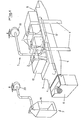
- the subject of the invention is also a device for implementing the method described above, characterized in that it essentially consists of a frame mounted on feet carrying individual modular freezing boxes and an electronic control cabinet, by a supply line for modular boxes in cryogenic gas, by a deep-freezing tunnel fitted under the frame and closed at its lower part by a conveyor belt mounted on a mobile watertight box, by a receiving tank provided in front of the tunnel exit , by a packaging station for packaging and filling the latter with a cryogenic product, by cryogenic gas circulation pipes between the caissons and the tunnel, by a device for extracting and discharging the residual gas heated outside the tunnel, and by a device for evacuating residual gas from the conditioning station.
- the modular caissons are juxtaposed and / or superimposed, and the supply line for all of the caissons with cryogenic gas is connected to a device for producing cryogenic product in the form of snow. provided with a container for receiving said product.
- each box is equipped with trays for supporting the products to be frozen, provided with a coating of non-stick material at very low temperature, in particular that known under the trade name RILSAN from the company ATO Chimie , and in its front part, above each plate, at least one cryogenic gas injection nozzle with a flat and wide jet, the refrigeration energy recovery unit also being equipped with such nozzles, the control of which is performed as a function of the temperature gradient reached in said box, and the cryogenic gas mixing fan is a centrifugal fan placed at the bottom of each box behind a plate provided with a Venturi-shaped opening and the edges of which are slightly spaced internal walls of the box so as to favor the mixing of the gas in said box and to accentuate the speed of the gases to improve the heat exchanges.
- the device further comprises a cold source constituted by a mechanical cold production installation connected in a manner known per se to plate exchangers arranged in front of the longitudinal, horizontal and vertical walls boxes, with spacing, and protected from the deep-freezing enclosure containing the product support trays by means of an inner circumferential wall connected to the bottom plate provided with the Venturi-shaped opening, so as to produce a ducting of the air propelled by the centrifugal fan along the exchangers.
- a cold source constituted by a mechanical cold production installation connected in a manner known per se to plate exchangers arranged in front of the longitudinal, horizontal and vertical walls boxes, with spacing, and protected from the deep-freezing enclosure containing the product support trays by means of an inner circumferential wall connected to the bottom plate provided with the Venturi-shaped opening, so as to produce a ducting of the air propelled by the centrifugal fan along the exchangers.
- the process of deep-freezing and packaging of individual products consists in treating small individual quantities of various products in modular boxes.
- individual freezing units 1 supplied with cryogenic gas via a pipe not shown, and which are each connected by pipes 2 to a freezing tunnel 3 so as to produce in the latter a low temperature level, and to be treated the larger quantities of products trapped in tunnel 3, which is provided with a conveyor belt 4 (FIG.
- the temperature level in said tunnel is kept very low, so that during its use, the expenditure of cryogenic gas to reach the freezing temperature will be more low, and thus the operating cycle will be faster.
- the individual modular boxes 1 are fixed to a frame 8 mounted on legs 9 and carrying, in addition, an electronic cabinet 10 for controlling the boxes 1 and the tunnel 3.
- the latter is arranged under the frame 8 and is closed in its part lower by the conveyor belt 4 and at its ends by known waterproof curtains.
- the conveyor belt 4 is mounted on a sealed box 11 which can be moved vertically along the legs 9 to apply the conveyor belt 4 in a sealed manner, by means of a double longitudinal joint, against the frame 8.
- the movement of the box 11 is produced, in a manner known per se, by means of jacks, or the like, and to allow efficient cleaning of the interior of the tunnel 3 and of the strip 4, the latter is maintained in an intermediate position in the open position of the box 11 by means of sliding retaining rods, and the actuating jacks of the box 11 can be controlled differently to allow an inclination of said box 11 favoring its cleaning.
- the receiving tank 6 mounted in front of the outlet of the tunnel 3 and in front of the strip 4 is intended for housing an insulating packaging to be filled with products leaving the tunnel 3.
- the packaging filled with products is moved to the packaging station 7 where said products are covered with a layer of cryogenic product before the packaging is closed, so as to maintain the cold chain during transport.
- the conveyor belt 4 is advantageously made of stainless steel and slides on plastic slides fixed on the chassis supporting the belt 4 in special guides allowing differential expansion between steel and synthetic material without stress and without deformation of the slides, and the motor. of the web of the strip 4 is also fixed to the chassis supporting the strip and drives the latter by means of chain wheels, the tension of the strip and its differential elongations being compensated for by an additional device known per se.
- the enclosure walls of the tunnel 3 as well as the walls of the box 11 are advantageously insulated by means of padding of expanded polyurethane foam.
- FIG. 3 represents an individual modular box 1 the walls of which are filled with a layer of expanded foam 12, and the door 13 of which is also provided with an insulating material, and which is provided with a ramp 14 for injecting cryogenic gas comprising one or more electromagnetic valves 15 for automatic adjustment of the quantity of gas to be injected, these valves being controlled by an electronic regulation device placed in the electronic control cabinet 10, and by a thermometric probe (not shown) arranged in the box 1. Inside each box 1 is also provided an axial fan 16 intended to put the gas in turbulence in order to improve the heat exchange between the products and the gas.
- cryogenic gas into the tunnel 3 is carried out in the same manner as for the caissons 1, and its turbulence is carried out by several axial fans fixed in the upper wall of the tunnel, the temperature monitoring being carried out by with two probes located near the entrance and near the exit of the tunnel 3.
- the device 5 for extracting and evacuating the heated residual gas consists of a line 17 connected to the two ends of the tunnel 3 and to a centrifugal extraction fan 18 sucking said gas and rejecting it outside the room, this fan 18 having advantageously two operating speeds for adaptation to the various possible gas flow rates.
- the cryogenic product packaging and filling station 7 is also equipped with a gas evacuation device in the form of a collecting means 19 connected to a centrifugal extraction fan 20.
- the cryogenic gas used is advantageously carbon dioxide, which has the property of sublimating into carbon dioxide snow during its heating.
- the electronic control cabinet 10 contains all the control elements and is hermetically closed, and all the functions of the device are signaled by means of indicator lights, safety switches enabling the device to be deactivated if necessary.
- the cabinet 10 contains prohibition circuits preventing any diffusion of cryogenic gas in the event of failure of the fans 18 and 20 or the opening of the tunnel 3 or of a door of a box 1.
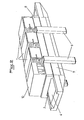
- the modular boxes 21 are juxtaposed and superimposed.
- the pipe 24 for supplying the cryogenic gay boxes 21 is advantageously connected, by means of a bypass 25 to a device 26 for producing cryogenic product in the form of snow provided with a container 27 for receiving said product.
- Each box is provided with trays 28 for supporting the products to be frozen, and a nozzle 29 for injecting cryogenic gas with a flat and wide jet is provided in the front part of the box above each plate 28.
- the recovery box for the refrigerating energy is also equipped with such nozzles 29 intended to provide the extra cold necessary for a rapid freezing process.
- the plates 28 are advantageously each provided with a coating of non-stick material at very low temperature, such as, in particular, that known under the trade name RILSAN.
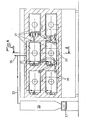
- each box 21 At the bottom of each box 21 is mounted a centrifugal fan 30 (FIG. 6) for mixing cryogenic gas, disposed behind a plate 31 provided with an opening 32 in the shape of a Venturi, and whose edges 33 are spaced slightly from the internal walls 34 of the box 21. Thanks to this embodiment, efficient mixing of the gas is carried out in the box 21, so that the speed of freezing is increased for a given quantity of injected gas.
- a centrifugal fan 30 for mixing cryogenic gas, disposed behind a plate 31 provided with an opening 32 in the shape of a Venturi, and whose edges 33 are spaced slightly from the internal walls 34 of the box 21.
- each box 21 is provided with a command and control device (not shown) comprising thermometric probes, a thermostat for displaying the treatment temperature, a device for sequential control of the injection of cryogenic gas, the injection and stop phases of which are preset, the operation of which is controlled by a thermometric probe, and the triggering of which is controlled by a push button simultaneously triggering the start of the fan 30 and a timer for monitoring the operation of the latter corresponding to the treatment time, the stopping of gas injection being controlled by another timer triggered simultaneously with the first and preset so as to stop the injection of gas while the mixing of gas in the box is still ensured by the fan, whose control timer is set for a longer period of time, for example a few minutes. Thanks to this embodiment, it is possible to better use the energy of the cryogenic gas by circulating said gas, at the desired temperature, at the end of the treatment, so that gas savings are possible.
- each box is equipped with a thermometric probe for controlling the treatment flow (not shown) triggering the control timers as soon as a temperature is reached. at the start of data processing.
- each modular box 21 is provided at its lowest point with a receiving orifice 35 connected to a flow pipe 36, these pipes 36 being advantageously connected to each other at the level of the refrigeration energy recovery box to lead into a common pipe 37.
- the latter is provided with a contact triggering a device for cutting off the injection of gas into all the other cells during said opening.
- FIG. 7 shows a possible alternative embodiment of a modular box 38, in which is provided, in addition, a cold source constituted by an installation 39 for producing mechanical cold, formed by two compressors 40 and 41 mounted in cascade, which is connected in a manner known per se to plate exchangers 42, which are arranged in front of the horizontal and vertical longitudinal walls of the box 38, at the spacing of these walls, and which are protected from the deep-freezing enclosure containing the trays 28 by means of an inner circumferential wall 43.
- the latter is connected to the plate bottom 31 provided with the venturi-shaped opening 32 opening onto the fan 30, so that a duct for the air propelled by the latter is made along the exchangers 42.
- the air circulated by the fan 30 allows rapid cooling of the products to be frozen.
- This embodiment is particularly advantageous for the freezing of large unpieced products for which freezing by cryogenics is relatively expensive, while the production of mechanical cold can practically be carried out continuously with a very low temperature gradient.
- cryogenic gas can be injected into the latter through a nozzle 44 disposed behind the fan 30.
- the gas injected by the nozzle 44 is rapidly circulated by the fan 30, and the products to be treated, seized by the sharp cold prevailing in the box due to the mechanical cold produced, undergoing very rapid freezing.
- the deep-freezing device comprises at least one modular box supplied with mechanical cold combined with a set of modular boxes supplied with cryogenic gas, at least one of which is intended for recovery of frigories and is also connected to the mechanical cold box.
Landscapes
- Engineering & Computer Science (AREA)
- Chemical & Material Sciences (AREA)
- Life Sciences & Earth Sciences (AREA)
- Polymers & Plastics (AREA)
- Zoology (AREA)
- Food Science & Technology (AREA)
- Wood Science & Technology (AREA)
- Combustion & Propulsion (AREA)
- Physics & Mathematics (AREA)
- Mechanical Engineering (AREA)
- Thermal Sciences (AREA)
- General Engineering & Computer Science (AREA)
- Devices That Are Associated With Refrigeration Equipment (AREA)
Priority Applications (1)
| Application Number | Priority Date | Filing Date | Title |
|---|---|---|---|
| AT82440015T ATE19299T1 (de) | 1981-05-29 | 1982-05-28 | Verfahren zur tiefkuehlung und zur verpackung einzelner produkte und vorrichtung zur durchfuehrung dieses verfahrens. |
Applications Claiming Priority (4)
| Application Number | Priority Date | Filing Date | Title |
|---|---|---|---|
| FR8110847A FR2506914A1 (fr) | 1981-05-29 | 1981-05-29 | Procede de surgelation et de conditionnement de produits individuels, et dispositif pour la mise en oeuvre de ce procede |
| FR8110847 | 1981-05-29 | ||
| FR8207197 | 1982-04-23 | ||
| FR8207197A FR2525747A2 (fr) | 1981-05-29 | 1982-04-23 | Procede de surgelation et de conditionnement de produits individuels, et dispositif pour la mise en oeuvre de ce procede |
Publications (3)
| Publication Number | Publication Date |
|---|---|
| EP0069688A2 EP0069688A2 (fr) | 1983-01-12 |
| EP0069688A3 EP0069688A3 (en) | 1983-03-16 |
| EP0069688B1 true EP0069688B1 (fr) | 1986-04-16 |
Family
ID=26222419
Family Applications (1)
| Application Number | Title | Priority Date | Filing Date |
|---|---|---|---|
| EP82440015A Expired EP0069688B1 (fr) | 1981-05-29 | 1982-05-28 | Procédé de surgélation et de conditionnement de produits individuels, et dispositif pour la mise en oeuvre de ce procédé |
Country Status (4)
| Country | Link |
|---|---|
| US (1) | US4448029A (enExample) |
| EP (1) | EP0069688B1 (enExample) |
| DE (1) | DE3270578D1 (enExample) |
| FR (1) | FR2525747A2 (enExample) |
Families Citing this family (19)
| Publication number | Priority date | Publication date | Assignee | Title |
|---|---|---|---|---|
| US4644754A (en) * | 1984-01-11 | 1987-02-24 | Carboxyque Francaise | Process and apparatus for cooling a charge of products |
| FR2567635B1 (fr) * | 1984-07-12 | 1986-12-05 | Carboxyque Francaise | Procede et appareil de refroidissement d'une charge de produits |
| US4594253A (en) * | 1984-03-21 | 1986-06-10 | Maurice Fradin | Method for mincing and prepackaging minced meat under controlled atmosphere and temperature |
| EP0170580B1 (fr) * | 1984-07-12 | 1988-06-01 | Carboxyque Francaise | Procédé et appareil de refroidissement d'une charge de produits |
| FR2588067B1 (fr) * | 1985-10-02 | 1988-05-13 | Air Liquide | Procede et tunnel de refroidissement superficiel de produits alimentaires |
| SE459764B (sv) * | 1987-08-06 | 1989-07-31 | Frigoscandia Contracting Ab | Frystunnel med nivaahaallning av kylmediet medelst ett braeddavlopp |
| US5077066A (en) * | 1987-11-12 | 1991-12-31 | The Clorox Company | Method for preparing frozen comestibles for consumption |
| FR2630818B1 (fr) * | 1988-05-02 | 1990-09-14 | Carboxyque Francaise | Enceinte et procede de traitement thermique comportant une phase de refroidissement |
| US4856285A (en) * | 1988-09-20 | 1989-08-15 | Union Carbide Corporation | Cryo-mechanical combination freezer |
| ATE84196T1 (de) * | 1989-10-13 | 1993-01-15 | Sauerstoffwerk Guttroff F Gmbh | Verfahren und einrichtung zum kuehlen und gefrieren von wasserhaltigen lebensmitteln. |
| US6003322A (en) * | 1997-10-20 | 1999-12-21 | Coldwave Systems Llc | Method and apparatus for shipping super frozen materials |
| NL1009914C2 (nl) * | 1998-08-21 | 2000-02-22 | Hoek Loos Bv | Werkwijze en inrichting voor het in diepgevroren verpakte toestand brengen van een voedingsmiddel. |
| US6789391B2 (en) | 2001-05-21 | 2004-09-14 | B. Eric Graham | Modular apparatus and method for shipping super frozen materials |
| US6422031B1 (en) | 2001-08-15 | 2002-07-23 | Maytag Corporation | Refrigeration appliance with impingement cooling system |
| DE10218298A1 (de) * | 2002-04-24 | 2003-11-06 | Linde Ag | Vorrichtung zur Absaugung von Gas aus Gefrieranlagen |
| US7294591B2 (en) * | 2002-12-13 | 2007-11-13 | Kimberly-Clark Worldwide, Inc. | Absorbent composite including a folded substrate and an absorbent adhesive composition |
| US20090064690A1 (en) * | 2007-09-06 | 2009-03-12 | John Martin Girard | System and method for cryogenic enhancement to mechanical freezers |
| US20090090112A1 (en) * | 2007-09-06 | 2009-04-09 | John Martin Girard | System and method for cryogenic enhancement to mechanical freezers |
| FR3083596A1 (fr) * | 2018-07-06 | 2020-01-10 | L'air Liquide, Societe Anonyme Pour L'etude Et L'exploitation Des Procedes Georges Claude | Procede et installation de recuperation et stockage des gaz froids issus d'equipements cryogeniques |
Family Cites Families (24)
| Publication number | Priority date | Publication date | Assignee | Title |
|---|---|---|---|---|
| FR1012509A (fr) * | 1949-10-27 | 1952-07-11 | Perfectionnements apportés aux procédés et appareils pour conserver par le froid les denrées périssables, plus spécialement le poisson | |
| US3004408A (en) * | 1957-09-25 | 1961-10-17 | Philips Corp | Cold installation designed more particularly for storage of ampullae |
| US3048989A (en) * | 1960-01-14 | 1962-08-14 | Liquefreeze Company Inc | Apparatus for freezing food |
| FR1251915A (fr) * | 1960-03-24 | 1961-01-20 | Liquefreeze Company Inc | Procédé de congélation des produits alimentaires |
| US3293877A (en) * | 1964-08-13 | 1966-12-27 | Continental Oil Co | Refrigerant flow control means |
| DE1501207A1 (de) * | 1965-03-20 | 1969-08-14 | Agefko Kohlensaeure Werke Gmbh | Allzweck-Behaelter-Transportfahrzeug,insbesondere zum Transport von Tiefkuehlguetern |
| FR1439553A (fr) * | 1965-06-30 | 1966-05-20 | Air Reduction | Procédé de congélation de produits alimentaires |
| US3361192A (en) * | 1966-02-07 | 1968-01-02 | Varo Inc Electrokinetics Div | Temperature chamber |
| US3389744A (en) * | 1966-05-18 | 1968-06-25 | Acme Markets Inc | Freezing method and apparatus |
| DE1751315A1 (de) * | 1968-05-10 | 1971-07-08 | Kueleg Gmbh Kuehlmoebel Und Em | Tiefkuehlgeraet |
| CA925714A (en) * | 1971-01-15 | 1973-05-08 | W. Ahara Peter | Method and apparatus for freezing material |
| US3708995A (en) * | 1971-03-08 | 1973-01-09 | D Berg | Carbon dioxide food freezing method and apparatus |
| FR2184405B1 (enExample) * | 1972-05-16 | 1974-09-27 | Air Liquide | |
| NL7317330A (enExample) * | 1972-12-22 | 1974-06-25 | ||
| US3892104A (en) * | 1973-09-20 | 1975-07-01 | David J Klee | Cryogenic freezer with variable speed gas control system |
| CA1006365A (en) * | 1973-12-10 | 1977-03-08 | Barron M. Moody | Freeze tunnel |
| FR2314457A1 (fr) * | 1975-06-12 | 1977-01-07 | Air Liquide | Procede et installation de refrigeration d'une charge d'objets en vrac |
| US4060400A (en) * | 1975-08-22 | 1977-11-29 | Henry L. Franke | Refrigerated semitrailer truck for long and local deliveries |
| US4127008A (en) * | 1976-11-01 | 1978-11-28 | Lewis Tyree Jr | Method and apparatus for cooling material using liquid CO2 |
| US4157650A (en) * | 1977-08-16 | 1979-06-12 | Raul Guibert | Cryogenic rapid food cooling machine |
| US4171625A (en) * | 1977-11-02 | 1979-10-23 | Formax, Inc. | Cryogenic freezing tunnel |
| DE2906748A1 (de) * | 1978-02-23 | 1979-08-30 | Boc Ltd | Kaelteanlage zur kuehlung mehrerer gesonderter kuehlbehaelter |
| FR2462673A1 (fr) * | 1979-08-03 | 1981-02-13 | Carboxyque Francaise | Enceinte de refrigeration |
| US4249388A (en) * | 1980-01-30 | 1981-02-10 | Demco, Inc. | Automatic liquid ice system |
-
1982
- 1982-04-23 FR FR8207197A patent/FR2525747A2/fr active Granted
- 1982-05-28 DE DE8282440015T patent/DE3270578D1/de not_active Expired
- 1982-05-28 EP EP82440015A patent/EP0069688B1/fr not_active Expired
- 1982-06-01 US US06/384,083 patent/US4448029A/en not_active Expired - Fee Related
Also Published As
| Publication number | Publication date |
|---|---|
| FR2525747B2 (enExample) | 1984-10-12 |
| EP0069688A2 (fr) | 1983-01-12 |
| DE3270578D1 (en) | 1986-05-22 |
| FR2525747A2 (fr) | 1983-10-28 |
| US4448029A (en) | 1984-05-15 |
| EP0069688A3 (en) | 1983-03-16 |
Similar Documents
| Publication | Publication Date | Title |
|---|---|---|
| EP0069688B1 (fr) | Procédé de surgélation et de conditionnement de produits individuels, et dispositif pour la mise en oeuvre de ce procédé | |
| EP0250318A1 (fr) | Procédé et tunnel de refroidissement | |
| EP0806618B1 (fr) | Dispositif et procédé de croûtage en ligne de produits | |
| EP0309319A1 (fr) | Installation de refroidissement d'un produit extrudé en continu | |
| EP0968395B1 (fr) | Chariot refrigere | |
| FR2476288A1 (fr) | Appareil pour porter des objets ou des articles a basse temperature | |
| EP1622461B2 (fr) | Installation de traitement de produits de la mer | |
| US3096627A (en) | Apparatus for quick freezing of bakery goods | |
| FR2616683A1 (fr) | Autoclave de sterilisation | |
| FR2506914A1 (fr) | Procede de surgelation et de conditionnement de produits individuels, et dispositif pour la mise en oeuvre de ce procede | |
| EP0035452B1 (fr) | Cellule de réfrigération ou de congélation rapide en continu | |
| FR2718834A1 (fr) | Congélateur comportant un dispositif pour congélation rapide à accumulateurs de froid. | |
| EP1110042A1 (fr) | Procede de refroidissement en continu de produits et dispositif de refroidissement correspondant | |
| CN212806214U (zh) | 食材保鲜真空速冻机 | |
| EP0601952B1 (fr) | Procédé de traitement thermique de produits alimentaires, notamment de cuisson de légumes, et dispositif pour sa mise en oeuvre | |
| EP0578523A1 (fr) | Installation de cuisson et de refroidissement en continu de produits alimentaires préconditionnés | |
| FR2520855A1 (fr) | Chambre froide destinee a la conservation de denrees alimentaires | |
| EP2340726B1 (fr) | Surgélateur de croûtage d'un produit alimentaire | |
| FR2808080A1 (fr) | Dispositif pour optimiser la surgelation en continu de produits en vrac, individuellement, une installation equipee dudit dispositif et application dudit dispositif | |
| FR2793006A1 (fr) | Procede et installation de refroidissement de produits en continu au moyen d'un fluide cryogenique | |
| EP1213551A1 (fr) | Dispositif et traitement de produits par un gaz et installation comportant un tel dispositif | |
| FR2560500A1 (fr) | Unite de decongelation | |
| FR2615071A1 (fr) | Dispositif de conservation des vegetaux et procede d'utilisation | |
| BE465927A (enExample) | ||
| FR2678363A1 (fr) | Dispositif de surgelation et de conservation de produits frais, notamment de boulangerie et de patisserie. |
Legal Events
| Date | Code | Title | Description |
|---|---|---|---|
| PUAI | Public reference made under article 153(3) epc to a published international application that has entered the european phase |
Free format text: ORIGINAL CODE: 0009012 |
|
| PUAL | Search report despatched |
Free format text: ORIGINAL CODE: 0009013 |
|
| AK | Designated contracting states |
Designated state(s): AT BE CH DE GB IT LI LU NL SE |
|
| AK | Designated contracting states |
Designated state(s): AT BE CH DE GB IT LI LU NL SE |
|
| 17P | Request for examination filed |
Effective date: 19830311 |
|
| GRAA | (expected) grant |
Free format text: ORIGINAL CODE: 0009210 |
|
| AK | Designated contracting states |
Kind code of ref document: B1 Designated state(s): AT BE CH DE GB IT LI LU NL SE |
|
| PG25 | Lapsed in a contracting state [announced via postgrant information from national office to epo] |
Ref country code: NL Effective date: 19860416 Ref country code: IT Free format text: LAPSE BECAUSE OF FAILURE TO SUBMIT A TRANSLATION OF THE DESCRIPTION OR TO PAY THE FEE WITHIN THE PRESCRIBED TIME-LIMIT;WARNING: LAPSES OF ITALIAN PATENTS WITH EFFECTIVE DATE BEFORE 2007 MAY HAVE OCCURRED AT ANY TIME BEFORE 2007. THE CORRECT EFFECTIVE DATE MAY BE DIFFERENT FROM THE ONE RECORDED. Effective date: 19860416 Ref country code: AT Effective date: 19860416 |
|
| REF | Corresponds to: |
Ref document number: 19299 Country of ref document: AT Date of ref document: 19860515 Kind code of ref document: T |
|
| REF | Corresponds to: |
Ref document number: 3270578 Country of ref document: DE Date of ref document: 19860522 |
|
| PG25 | Lapsed in a contracting state [announced via postgrant information from national office to epo] |
Ref country code: LU Free format text: LAPSE BECAUSE OF NON-PAYMENT OF DUE FEES Effective date: 19860531 |
|
| NLV1 | Nl: lapsed or annulled due to failure to fulfill the requirements of art. 29p and 29m of the patents act | ||
| PLBE | No opposition filed within time limit |
Free format text: ORIGINAL CODE: 0009261 |
|
| STAA | Information on the status of an ep patent application or granted ep patent |
Free format text: STATUS: NO OPPOSITION FILED WITHIN TIME LIMIT |
|
| 26N | No opposition filed | ||
| PG25 | Lapsed in a contracting state [announced via postgrant information from national office to epo] |
Ref country code: SE Effective date: 19870529 |
|
| BERE | Be: lapsed |
Owner name: KELLER JEAN-PAUL Effective date: 19870531 |
|
| PG25 | Lapsed in a contracting state [announced via postgrant information from national office to epo] |
Ref country code: DE Effective date: 19880202 |
|
| GBPC | Gb: european patent ceased through non-payment of renewal fee | ||
| PG25 | Lapsed in a contracting state [announced via postgrant information from national office to epo] |
Ref country code: LI Effective date: 19880531 Ref country code: CH Effective date: 19880531 |
|
| PG25 | Lapsed in a contracting state [announced via postgrant information from national office to epo] |
Ref country code: GB Free format text: LAPSE BECAUSE OF NON-PAYMENT OF DUE FEES Effective date: 19881121 |
|
| REG | Reference to a national code |
Ref country code: CH Ref legal event code: PL |
|
| PG25 | Lapsed in a contracting state [announced via postgrant information from national office to epo] |
Ref country code: BE Effective date: 19890531 |
|
| EUG | Se: european patent has lapsed |
Ref document number: 82440015.4 Effective date: 19880616 |